

Page 1
Mounting instructions
Protective cover
Document ID:
34296
Page 2

1 Contents
Contents
1 For yo
2 Product description
3 Mounting
4 Supplement
ur safety
1.1 Authorised personnel . . . . . . . . . . . . . . . . . . . . . . ..
1.2 Appropriate use . . . . . . . . . . . . . . . . . . . . . . . . . . . .
1.3 General safety instructions . . . . . . . . . . . . . . . . . . . .
1.4 Safety instructions for Ex areas . . . . . . . . . . . . . . . . .
2.1 Structure . . . . . . . . . . . . . . . . . . . . . . . . . . . . . . . . .
2.2 Principle of operation . . . . . . . . . . . . . . . . . . . . . . . .
3.1 Mounting preparations . . . . . . . . . . . . . . . . . . . . . . .
3.2 Mounting steps. . . . . . . . . . . . . . . . . . . . . . . . . . . . .
4.1 Technical data . . . . . . . . . . . . . . . . . . . . . . . . . . . . .
4.2 Dimensions . . . . . . . . . . . . . . . . . . . . . . . . . . . . . . .
3
3
3
3
4
5
6
6
8
9
Editing status: 2012-04-18
2 Protective cover
34296-EN-120516
Page 3

1 For your safety
1 For your safety
1.1 Auth
All operations described in this operating instructions manual must be
carried out only by trained specialist personnel authorised by the plant
operator.
During work on and with the device the required personal protective
equipment must always be worn.
orised personnel
1.2 Appropriate use
The protective cover is an accessory or retrofit part for sensors from
the VEGA plics
®
line of products.
1.3 General safety instructions
The safety information in the operating instructions manual of the
respective sensor must be noted.
1.4 Safety instructions for Ex areas
Please note the Ex-specific safety information for installation and
operation in Ex areas. These safety instructions are part of the
operating instructions manual and come with the Ex-approved
instruments.
34296-EN-120516
Protective cover 3
Page 4
2 Product description
2 Product description
2.1 Structure
pe of delivery
Sco
Constituent parts
e scope of delivery encompasses:
Th
l Protective cover
l Documentation
- this operating instructions manual
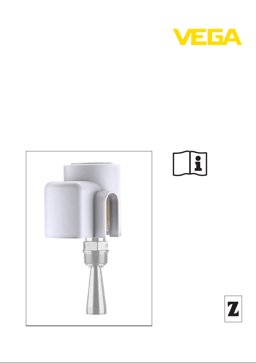
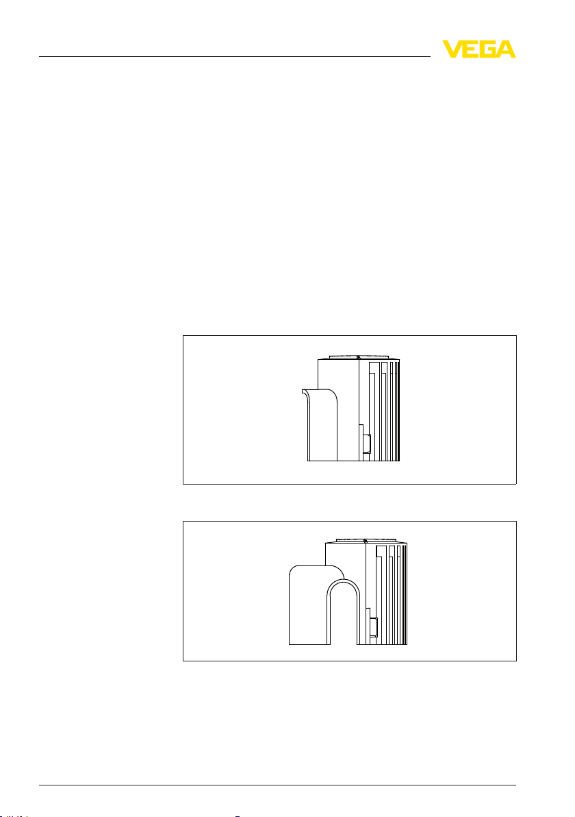
The protective cover is available in two versions:
l For single chamber housing (plastic and stainless steel)
l For double chamber housing and Aluminium single chamber
housing
The two versions differ in configuration and size; function and handling
are identical.
cover
Fig. 1: Protective
single chamber housing
for
Fig. 2: Protective cover for
chamber housing
4 Protective cover
double chamber housing und Aluminium single
34296-EN-120516
Page 5

2 Product description
Application area
Functional principle
2.2 Principle of
The protective cover is an accessory or retrofit part for level, switching
and pressure sensors from the VEGA plics® product line. It is suitable
for sensors with or without indicating and adjustment module. The
height difference of the housing is compensated by the supplied foam
rubber adapter disc.
With double chamber housings, the indicating and adjustment module
must be mounted on top.
The protective cover protects the sensor housing against soiling and
intense heat from solar radiation when it is mounted outdoors.
It consists of two half-shells with hinge held together by a snap-on
connection. A secure hold on the sensor housing is ensured via
fastening elements. Ventilation slots allow air circulation.
The protective cover is put on after the sensor is mounted and
commissioned. It is not necessary to interrupt the electrical connection.
operation
34296-EN-120516
Protective cover 5
Page 6

2
1
2
1
3 Mounting
3 Mounting
Tools
3.1 Mounting
No tools are required for mounting.
preparations
3.2 Mounting steps
Proceed as follows:
1 Open the snap connection by pressing on the smooth housing half
Fig. 3: Loosen
1 Version for single chamber housing
2 Version for double chamber housing
2 Opening the protective cover
the
connection by pushing and pulling
snap-on
Fig. 4: Opening the protective
1 Version for single chamber housing
2 Version for double chamber housing
3 In case of sensor housing with integrated indicating and adjust-
ment module, remove the foam rubber disc
4 Slide the protective cover over the sensor housing
6 Protective cover
cover
34296-EN-120516
Page 7

2
1
3 Mounting
5 Close the protective cover and snap in the snap connection
Fig. 5: Close the protective
1 Version for single chamber housing
2 Version for double chamber housing
cover
6 Check if the protective cover is sitting firmly on the sensor housing
Assembly is finished.
Dismounting is carried out correspondingly in reverse order.
34296-EN-120516
Protective cover 7
Page 8

4 Supplement
4 Supplement
4.1 Technical
General data
Material plastic PBT
Colour Tele grey (RAL 7047)
Weight approx. 0.3 kg (0.661 lbs)
Ambient conditions
Ambient, storage and transport temperature
data
-40 … +80 °C (-40 … +176 °F)
8 Protective cover
34296-EN-120516
Page 9

4.2 Dimensions
ø 110 mm (4
21
/64")
ø 170 mm (6
11
/16")
142 mm (5
19
/
32
")
140 mm (5
33
/
64
")
tive cover for single chamber housing
Protec
4 Supplement
Fig. 6: Protective
34296-EN-120516
Protective cover 9
cover
single chamber housing
for
Page 10

ø 110 mm (4
21
/64")
ø 206 mm (8
7
/64")
142 mm (5
19
/
32
")
ca. 140 mm (5
33
/
64
")
4 Supplement
Protective cover for double chamber housing
Fig. 7: Protective cover for
double chamber housing und Aluminium single chamber housing
10 Protective cover
34296-EN-120516
Page 11

4 Supplement
34296-EN-120516
Protective cover 11
Page 12

VEGA Grieshaber KG
ISO 9001
Am Hohenstein 113
77761 Schiltach
Germany
Phone +49 7836 50-0
Fax +49 7836 50-201
E-mail: info.de@vega.com
www.vega.com
Printing date:
All statements concerning scope of delivery, application,
practical use
and operating conditions of the sensors and
processing systems correspond to the information avail-
able at the time of printing.
© VEGA Grieshaber KG, Schiltach/Germany 2012
Subject to change without prior notice 34296-EN-120516
 Loading...