

Page 1
Ope
rating Instructions
Conductive probe EL 3
Document ID:
32652
Cond
uctive
Page 2

Contents
Conten
1 About this document
2 For your safety
3 Product description
4 Mounting
5 Connecting to power supply
6 Set up
ts
1.1 Function. . . . . . . . . . . . . . . . . . . . . . . . . . . . . . . . . .
1.2 Target group . . . . . . . . . . . . . . . . . . . . . . . . . . . . . .
1.3 Symbolism used . . . . . . . . . . . . . . . . . . . . . . . . . . . .
2.1 Authorised personnel . . . . . . . . . . . . . . . . . . . . . . . .
2.2 Appropriate use . . . . . . . . . . . . . . . . . . . . . . . . . . . .
2.3 Warning about misuse . . . . . . . . . . . . . . . . . . . . . . .
2.4 General safety instructions . . . . . . . . . . . . . . . . . . . .
2.5 Safety instructions for Ex areas . . . . . . . . . . . . . . . . .
2.6 Environmental instructions. . . . . . . . . . . . . . . . . . . . .
3.1 Configuration . . . . . . . . . . . . . . . . . . . . . . . . . . . . . .
3.2 Principle of operation . . . . . . . . . . . . . . . . . . . . . . . .
3.3 Operation. . . . . . . . . . . . . . . . . . . . . . . . . . . . . . . . .
3.4 Storage and transport . . . . . . . . . . . . . . . . . . . . . . .
4.1 General instructions . . . . . . . . . . . . . . . . . . . . . . . . .
4.2 Mounting instructions . . . . . . . . . . . . . . . . . . . . . . . .
5.1 Preparing the connection . . . . . . . . . . . . . . . . . . . . .
5.2 Wiring plan . . . . . . . . . . . . . . . . . . . . . . . . . . . . . . .
6.1 General information . . . . . . . . . . . . . . . . . . . . . . . . .
3
3
3
4
4
4
4
5
5
6
7
7
8
9
10
12
12
15
7 Maintenance and fault rectification
7.1 Maintenance . . . . . . . . . . . . . . . . . . . . . . . . . . . . . .
7.2 Rectify malfunctions . . . . . . . . . . . . . . . . . . . . . . . . .
7.3 Shortening the probe . . . . . . . . . . . . . . . . . . . . . . . .
7.4 Instrument repair . . . . . . . . . . . . . . . . . . . . . . . . . . .
8 Dismounting
8.1 Dismounting steps . . . . . . . . . . . . . . . . . . . . . . . . . .
8.2 Removal . . . . . . . . . . . . . . . . . . . . . . . . . . . . . . . . .
9 Supplement
9.1 Technical data . . . . . . . . . . . . . . . . . . . . . . . . . . . . .
9.2 Dimensions . . . . . . . . . . . . . . . . . . . . . . . . . . . . . . .
9.3 Industrial property rights . . . . . . . . . . . . . . . . . . . . . .
9.4 Trademark . . . . . . . . . . . . . . . . . . . . . . . . . . . . . . .
2 Cond
16
16
16
16
18
18
19
21
22
22
uctive probe EL 3
32652-EN-100208
Page 3
out this document
1 Ab
1 Abou
t this document
1.1 Function
This operating instructions manual provides all the information you
need for mounting, connection and setup as well as important
instructions for maintenance and fault rectification. Please read this
information before putting the instrument into operation and keep this
manual accessible in the immediate vicinity of the device.
1.2 Target group
This operating instructions manual is directed to trained qualified
personnel. The contents of this manual should be made available to
these personnel and put into practice by them.
1.3 Symbolism used
Inform
ation, tip, note
This symbol indicates helpful additional information.
Cauti
on: If this warning is ignored, faults or malfunctions can
result.
Warning: If this warning is ignored, injury to persons and/or serious
damage to the instrument can result.
Danger: If this warning is ignored, serious injury to persons and/or
destruction of the instrument can result.
applications
Ex
This symbol indicates special instructions for Ex applications.
32652-EN-100208
Condu
l List
The dot set in front indicates a list with no implied sequence.
à Action
Th
is arrow indicates a single action.
1 Sequence
Numbers set in front indicate successive steps in a procedure.
ctive probe EL 3 3
Page 4

2 For
your safety
or your safety
2 F
2.1 Authorised personnel
All operations described in this operating instructions manual must be
carried out only by trained specialist personnel authorised by the plant
operator.
During work on and with the device the required personal protective
equipment must always be worn.
2.2 Appropriate use
The EL 3 is a sensor for level detection.
You can find detailed information on the application range in chapter
"Product description".
Operational reliability is ensured only if the instrument is properly used
according to the specifications in the operating instructions manual as
well as possible supplementary instructions.
For safety and warranty reasons, any invasive work on the device
beyond that described in the operating instructions manual may be
carried out only by personnel authorised by the manufacturer. Arbitrary
conversions or modifications are explicitly forbidden.
2.3 Warning about misuse
Inappropriate or incorrect use of the instrument can give rise to
application-specific hazards, e.g. vessel overfill or damage to system
components through incorrect mounting or adjustment.
2.4 General safety instructions
This is a high-tech instrument requiring the strict observance of
standard regulations and guidelines. The user must take note of the
safety instructions in this operating instructions manual, the countryspecific installation standards as well as all prevailing safety
regulations and accident prevention rules.
The instrument must only be operated in a technically flawless and
reliable condition. The operator is responsible for trouble-free
operation of the instrument.
During the entire duration of use, the user is obliged to determine the
compliance of the required occupational safety measures with the
current valid rules and regulations and also take note of new
regulations.
4 Cond
32652-EN-100208
uctive probe EL 3
Page 5

2 For
your safety
2.5 Safety
Please note the Ex-specific safety information for installation and
operation in Ex areas. These safety instructions are part of the
operating instructions manual and come with the Ex-approved
instruments.
instructions for Ex areas
2.6 Environmental instructions
Protection of the environment is one of our most important duties. That
is why we have introduced an environment management system with
the goal of continuously improving company environmental protection.
The environment management system is certified according to DIN
EN ISO 14001.
Please help us fulfil this obligation by observing the environmental
instructions in this manual:
l Chapter "Packaging, transport and storage"
l Chapter "Disposal"
32652-EN-100208
Condu
ctive probe EL 3 5
Page 6
1
2
3
3 Produc
t description
Scope of delivery
Constituents
3 Produc
t description
3.1 Configuration
The scope of delivery encompasses:
l EL 3 point level sensor
l Documentation
- this operating instructions manual
- Ex-specific "Safety instructions" (with Ex versions)
- if necessary, further certificates
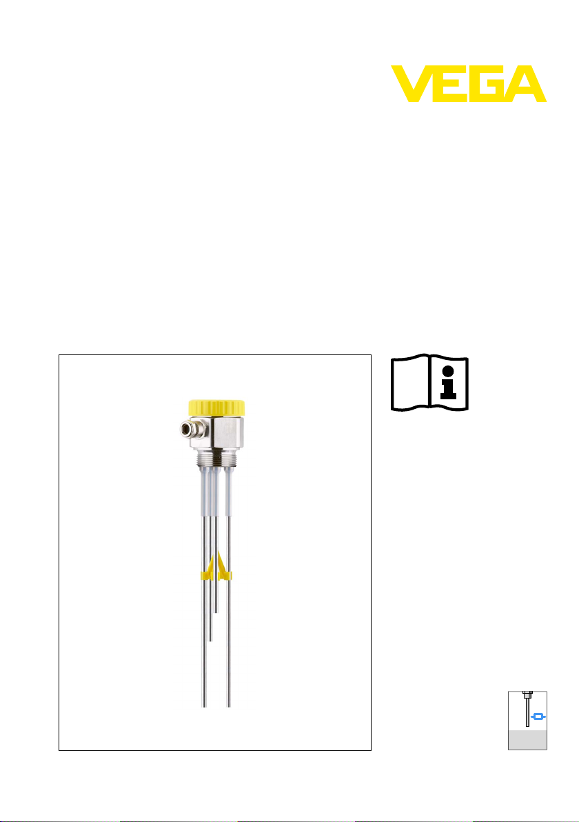
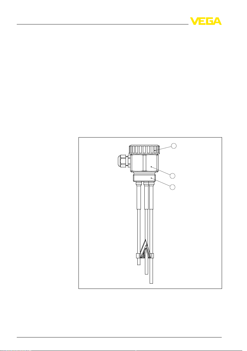
The EL 3 consist of the following components:
l Housing cover
l Housing
l Process fitting with electrode
Fig. 1: Conductive
1 Housing cover
2 Housing
3 Process fitting
To create a measuring system you need one conductive probe and a
VEGATOR 256C, 532 or 631 signal conditioning instrument.
6 Cond
multiple rod electrode EL 3
32652-EN-100208
uctive probe EL 3
Page 7

Type label
3 Produc
e type label contains the most important data for identification a nd
Th
use of the instrument:
l Article number
l Serial number
l Technical data
l Article numbers, documentation
With the serial number, you can access the delivery data of the
instrument via
search". In addition to the type label outside, you can also find the
serial number on the inside of the instrument.
www.vega.com, "VEG
A Tools" and "serial number
t description
3.2 Principle of operation
Application area
Functional principle
Voltage supply
EL 3 is a point level sensor with partly insulated conductive electrode
for level detection.
EL 3 is very rugged and can be used in all areas of industrial process
technology.
The level switch can be used in conductive liquids such as e.g. water.
Typical applications are overfill and dry run protection.
The conductive measuring principle places no special requirements on
installation. Hence, many different applications can be equipped with
EL 3.
Conductive probes detect the product resistance when their electro-
des are covered by the product.
The switching signal is determined by the length or mounting position
of the respective electrode.
A low alternating current flows through the electodes, is measured for
amplitude and phase position by the electronics of the signal
conditioning instrument and converted into a switching command.
EL 3 is operated with an external processing unit. The connected
signal conditioning instrument powers EL 3 and provides a switching
signal. A connected device can be activated directly with this switching
command (e.g. a warning sys tem, a PLC, a pump, etc.).
You can find the exact range of the voltage supply in chapter
"Technical data" in the operating instructions manual of the signal
conditioning instrument.
32652-EN-100208
Condu
3.3 Operation
The probe does not have its own electronics. The measurement is
carried out via the connected signal conditioning instrument.
ctive probe EL 3 7
Page 8

3 Produc
t description
Packaging
Transport
Transport inspection
Storage
Storage and transport
temperature
3.4 Stora
ge and transport
Your instrument was protected by packaging during transport. Its
capacity to handle normal loads during transport is assured by a test
according to DIN EN 24180.
The packaging of standard instruments consists of environmentfriendly, recyclable cardboard. For special versions, PE foam or PE foil
is also used. Dispose of the packaging material via specialised
recycling companies.
Transport must be carried out under consideration of the notes on the
transport packaging. Nonobservance of these instructions can cause
damage to the device.
The delivery must be checked for completeness and possible transit
damage immediately at receipt. Ascertained transit damage or
concealed defects must be appropriately dealt with.
Up to the time of installation, the packages must be left closed and
stored according to the orientation and storage markings on the
outside.
Unless otherwise indicated, the packages must be stored only under
the following conditions:
l Not in the open
l Dry and dust free
l Not exposed to corrosive media
l Protected against solar radiation
l Avoiding mechanical shock and vibration
l Storage and transport temperature see chapter "Supplement -
Technical data - Ambient conditions"
l Relative humidity 20 … 85 %
8 Cond
32652-EN-100208
uctive probe EL 3
Page 9

4 M
ounting
Switching point
Handling
Moisture
4 Moun
ting
4.1 General instructions
In general the level switch can be mounted in any position. The
instrument must be mounted in such a way that the probe is at the
height of the requested switching point.
The probe is provided with a special hexagon for tightening. Due to the
hexagon shape, the housing itself can be used to screw the instrument
in.
The wrench size is stated in chapter "Supplement" under "Dimen-
sions".
Use the recommended cables (see chapter "Connecting to power
supply") and tighten the cable gland.
You can give your EL 3 additional protection against moisture
penetration by leading the connection cable downward in front of the
cable entry. Rain and condensation water can thus drain off. This
applies mainly to outdoor mounting as well as installation in areas
where high humidity is expected (e.g. through cleaning processes) or
on cooled or heated vessels.
Transport
Pressure/Vacuum
32652-EN-100208
Condu
ctive probe EL 3 9
Fig. 2: Measures
Do not hold EL 3 on its electrode rods. Particularly with long rod
versions, the sensor can be damaged by the weight of the instrument.
The process fitting must be sealed if there is gauge or low pressure in
the vessel. Before use, check if the seal material is resistant against
the measured product and the process temperature.
The max. permissible pressure is specified in chapter "Technical data"
or on the type label of the sensor.
against moisture penetration
Page 10

1
2
1
2
4 M
ounting
Agitators and fluidization
4.2 Mount
Due to agitators, equipment vibration or similar, the level switch can be
subjected to strong lateral forces.
Extreme vibration caused by the system, e.g. due to agitators or
turbulence in the vessel from fluidization, can cause the probe of EL 3
to vibrate in resonance. If a longer rod version is necessary, you can
secure the probe by fastening a suitable insulating brace or guy
directly above the end of the rod.
Fig. 3: Fasten
1 Probe
2 Plastic sleeve at the probe end or laterally mounted
ing instructions
the probe
Inflowing medium
If EL 3 is mounted in the filling stream, unwanted false measurement
signals can be generated. For this reason, mount EL 3 at a position in
the vessel where no disturbances, e.g. from filling openings, agitators,
etc., can occur.
This applies particularly to instrument versions with a longer probe.
10 Cond
32652-EN-100208
uctive probe EL 3
Page 11

4 M
ounting
Socket
Ground connection
Fig. 4: Inflowing
medium
The probe should protrude into the vessel to avoid buildup. For that
reason, avoid using high mounting bosses for screw-in fittings. This
applies particularly to use in adhesive products.
Make su re that the mechanical connection of the probe to the vessel is
electrically conductive to ensure sufficient grounding.
Use conductive seals, such as those made of copper or lead, etc.
Insulating measures, such as covering the thread with Teflon tape, can
interrupt the necessary electrical connection with metal vessels. For
this reason, ground the probe on the vessel or use a conductive seal
material.
32652-EN-100208
Condu
ctive probe EL 3 11
Page 12

ecting to power supply
5 Conn
Note safety instructions
Voltage supply
Connection cable
Connection compart-
ment
5 Conn
ecting to power supply
5.1 Preparing the connection
Always keep in mind the following safety instructions:
l Connect only in the complete absence of line voltage
You can find the electrical connection of EL 3 in the operating
instructions manual of the corresponding signal conditioning instrument.
You can find suitable signal conditioning instruments in chapter
"Technical data".
The instrument is connected with standard two-wire cable without
screen. If electromagnetic interference is expected which is above the
test values of EN 61326 for industrial areas, screened cable should be
used.
Use cable with round cross-section. A cable outer diameter of 5 … 9 mm
(0.2 … 0.35 in) ensures the seal effect of the cable gland. If you are
using cable with a different diameter or cross-section, exchange the
seal or use a suitable cable gland.
5.2 Wiring plan
You can find the electrical connection of EL 3 in the operating
instructions manual of the corresponding signal conditioning instrument.
Line monitoring with
VEGATOR 631
12 Cond
To realize a line monitoring with a VEGATOR 631 signal conditioning
instrument, a resistor of 220 kΩ must be integrated in the connection
housing of the probe between terminal 1 and 2.
When a fault message is generated, the switching output is
simultaneously activated.
If a fault message is not wanted, a bridge must be provided on the
signal conditioning instrument instead of the resistor in the connection
housing of the probe.
The line monitoring is thus deactivated and the fault message
rendered invalid.
Take note of the operating instructions manual of the signal
conditioning instrument.
With Ex
the connection housing of the probe. The Ex measuring system (max.
and ground connection cable of the probe to the signal conditioning
instrument) is generally monitored for line break.
l Terminal 1 = longest rod (ground)
versions, this 220 kΩ resistor is already integrated ex factory in
32652-EN-100208
uctive probe EL 3
Page 13

1
2
3
4
5
4
3
2
1
2
3
1
1
2
2
2
3
4
1
2
3
4
1
5
2
3
1
1
A B
C D
ecting to power supply
5 Conn
Line monitoring with
VEGATOR 632
l Term
Fig. 5: Connection
terminals 1 and 2
1 Connection terminal 1 = longest rod
2 Connection terminal 2 = shortest rod
A Probe with 2 rods
B Probe with 3 rods
C Probe with 4 rods
D Probe with 5 rods
inal 2 = shortest rod (max.)
compartment of the probe - 220 kΩ resistance between
The line break monitoring or alarm function defines the function of the
signal conditioning instrument in case of failure.
To realize line monitoring with a signal conditioning instrument
VEGATOR 632, an additional component must be mounted in the
connection housing of the probe.
32652-EN-100208
Condu
Fig. 6: Component
ctive probe EL 3 13
for line break monitoring in conjunction with VEGATOR 632
Page 14

1
2
ecting to power supply
5 Conn
1 Connec
t the eyelet according to the following illustration.
Make sure that the eyelets have no contact to other metal parts.
2 Open one of the other terminals and attach the component.
3 Tighten the terminal.
Fig. 7: Mounting
1 Connection to terminal 1 (ground rod = longest rod)
2 Connection to terminal 2 (max. rod = shortest rod)
3 Component for line break monitoring with VEGATOR 632
of the component for line break monitoring
If you are using a probe without component for line break monitoring, a
fault signal will be triggered.
Keep in mind that in case of a fault signal also the switching output will
be activated.
Only failures of channel 1 are monitored.
Take note of the operating instructions manual of the signal
conditioning instrument.
14 Cond
32652-EN-100208
uctive probe EL 3
Page 15

6 Set
up
6 Set
up
6.1 General information
You can find the setup procedure for EL 3 in the operating instructions
manual of the corresponding signal conditioning instrument.
32652-EN-100208
Condu
ctive probe EL 3 15
Page 16

aintenance and fault rectification
7 M
Causes of malfunction
Fault rectification
24 hour service hotline
7 Maint
enance and fault rectification
7.1 Maintenance
When used as directed in normal operation, EL 3 is completely
maintenance free.
7.2 Rectify malfunctions
EL 3 offers maximum reliability. Nevertheless, faults can occur during
operation. These may be caused by the following, e.g.:
l Sensor
l Process
l Voltage supply
l Signal processing
You can find information on fault rectification in the operating
instructions manual of the corresponding signal conditioning instrument.
However, should these measures not be successful, call the VEGA
service hotline in urgent cases under the phone no. +49 1805 858550.
The hotline is available to you 7 days a week round-the-clock. Since
we offer this service world-wide, the support is only available in the
English language. The service is free of charge, only the standard
telephone costs will be charged.
7.3 Shortening the probe
The probe can be shortened by any amount.
Note:
ke note when shortening multiple probes that terminal 1 corre-
Ta
sponds to the longest probe and terminal 2 to the shortest probe.
7.4 Instrument repair
If a repair is necessary, please proceed as follows:
You can download a return form (23 KB) from our Internet homepage
www.vega.com
form".
By doing this you help us carry out the repair quickly and without
having to call back for needed information.
l Print and fill out one form per instrument
l Clean the instrument and pack it damage-proof
16 Cond
under: "Downloads - Forms and certificates - Repair
32652-EN-100208
uctive probe EL 3
Page 17

aintenance and fault rectification
7 M
ch the completed form and, if need be, also a safety data
l Atta
sheet outside on the packaging
l Please ask the agency serving you for the address of your return
shipment. You can find the respective agency on our website
www.vega.com under: "Company - VEGA worldwide"
32652-EN-100208
Condu
ctive probe EL 3 17
Page 18

8 Dismoun
ting
8 Dismou
nting
8.1 Dismounting steps
Warning:
Before dismounting, be aware of dangerous process conditions such
as e.g. pressure in the vessel, high temperatures, corrosive or toxic
products etc.
Take note of chapters "Mounting" and "Connecting to power supply"
and carry out the listed steps in reverse order.
8.2 Removal
The instrument consists of materials which can be recycled by
specialised recycling companies. We use recyclable materials and
have designed the electronics to be easily separable.
WEEE directive 2002/96/EG
This instrument is not subject to the WEEE directive 2002/96/EG and
the respective national laws. Pass the instrument directly on to a
specialised recycling company and do not use the municipal collecting
points. These may be used only for privately used products according
to the WEEE directive.
Correct disposal avoids negative effects to persons and environment
and ensures recycling of useful raw materials.
Materials: see chapter "Technical data"
If you have no possibility to dispose of the old instrument
professionally, please contact us concerning return and disposal.
18 Cond
32652-EN-100208
uctive probe EL 3
Page 19

9 Sup
plement
9 Supp
lement
9.1 Technical data
General data
Materials 316Ti corresponds to 1.4571, 316L corresponds to 1.4404 or 1.4435
Materials, wetted parts
- Process fitting 316Ti
- Process seal Klingersil C-4400
- insulation (partly insulated) PTFE
- Probe (rod partly PTFE insulated: ø 6 mm/
0.236 in)
Materials, non-wetted parts
- Housing 316Ti
- Housing cover PBT
- Seal between housing and housing
cover
- Cable gland brass, nickel-plated
Process fitting G1½ A (ISO 228 T1)
Weight
- with stainless steel housing 900 g (32 oz)
- Rod weight: ø 6 mm (0.236 in) 220 g/m (2.4 oz/ft)
Sensor length (L1 - L5) 0.1 … 6 m (0.328 … 19.69 ft)
Insulation length 78 mm (3.15 in)
316Ti, Hastelloy C4 (2.4610)
NBR
Output variable
Suitable signal conditioning instruments VEGATOR 256C, 532, 631
Ambient conditions
Ambient temperature on the housing -40 … +80 °C (-40 … +176 °F)
Storage and transport temperature -40 … +80 °C (-40 … +176 °F)
Process conditions
Process pressure -1 … 63 bar/-100 … 6300 kPa (-14.5 … 914 psig)
Process temperature EL 3 of 316L -50 … +130 °C (-58 … +266 °F)
Conductive of the medium min. 7.5 µS/cm
Electromechanical data
Cable entry 1 x cable gland M20 x 1.5 (cable: ø 5 … 9 mm/
32652-EN-100208
Condu
ctive probe EL 3 19
0.2 … 0.35 in)
Page 20

9 Suppl
Electri
Protection rating IP 66/IP 67
Approvals
Depending on the version, instruments with approvals can have different technical data.
For these instruments, the corresponding approval documents have to be taken into account.
These are part of the delivery or can be downloaded under
"serial number search" as well as via "Downloads" and "Approvals".
ement
cal protective measures
www.vega.com
via "VEGA Tools" and
20 Cond
32652-EN-100208
uctive probe EL 3
Page 21

9.2 D
M20x1,5
66mm (2 19/32")
57mm (2 1/4")
ø 6mm
(15/64")
59mm (2
21
/
64
") 80mm (3
5
/
32
")
SW 60mm
(2 23/64")
G1½A
20mm
(
25
/
32
")
L3
L1
L2
imensions
9 Sup
plement
Fig. 8: Conductive
multiple rod electrode EL 3
L1 Sensor length, see chapter "Technical data"
L2 Sensor length, see chapter "Technical data"
L3 Sensor length, see chapter "Technical data"
32652-EN-100208
Condu
ctive probe EL 3 21
Page 22

9 Suppl
ement
9.3 Indus
VEGA product lines are global protected by industrial property rights.
Further information see http://www.vega.com.
Only in U.S.A.: Further information see patent label at the sensor
housing.
VEGA Produktfamilien sind weltweit geschützt durch gewerbliche
Schutzrechte.
Nähere Informationen unter http://www.vega.com.
Les lignes de produits VEGA sont globalement protégées par des
droits de propriété intellectuelle.
Pour plus d'informations, on pourra se référer au site http://www.vega.
com.
VEGA lineas de productos están protegidas por los derechos en el
campo de la propiedad industrial.
Para mayor información revise la pagina web http://www.vega.com.
Линии продукции фирмы ВЕГА защищаются по всему миру
правами на интеллектуальную собственность.
Дальнейшую информацию смотрите на сайте http://www.vega.com.
VEGA系列产品在全球享有知识产权保护。
进一步信息请参见网站<http://www.vega.com>。
trial property rights
9.4 Trademark
All the brands as well as trade and company names used are property
of their lawful proprietor/originator.
22 Cond
32652-EN-100208
uctive probe EL 3
Page 23

9 Sup
plement
32652-EN-100208
Condu
ctive probe EL 3 23
Page 24

VEGA Grieshaber KG
ISO 9001
Am Hohenstein 113
77761 Schiltach
Germany
Phone +49 7836 50-0
Fax +49 7836 50-201
E-mail: info@de.vega.com
www.vega.com
Printing date:
statements concerning scope of delivery, application,
All
practical use and operating conditions of the sensors and
processing systems correspond to the information avail-
able at the time of printing.
© VEGA Grieshaber KG, Schiltach/Germany 2010
Subject to change without prior notice 32652-EN-100208
 Loading...