

Page 1
Supplementary instructions
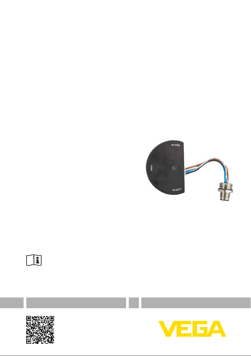
DIS-ADAPT
Adapter for connection of an external display and adjustment unit
Document ID: 45250
Page 2

Contents
Contents
1 For your safety
1.1 Appropriate use ................................................................................................................ 3
1.2 General safety instructions ............................................................................................... 3
1.3 Safety instructions for Ex areas ........................................................................................ 3
2 Product description
3 Mounting
3.1 Mounting preparations ..................................................................................................... 5
3.2 Mounting steps ................................................................................................................. 5
4 Connecting
5 Supplement
5.1 Technical data .................................................................................................................. 9
5.2 Dimensions ..................................................................................................................... 9
45250-EN-130625
Editing status: 2013-11-06
2
DIS-ADAPT • Adapter for connection of an external display and adjustment unit
Page 3

1 For your safety
1 For your safety
1.1 Appropriate use
DIS-ADAPT is a retrot component for existing plics® sensors for con-
nection of an external display and adjustment unit.
1.2 General safety instructions
The safety information in the operating instructions manual of the
respective sensor must be noted.
1.3 Safety instructions for Ex areas
Please note the Ex-specic safety information for installation and operation in Ex areas. These safety instructions are part of the operating
instructions manual and come with the Ex-approved instruments.
45250-EN-130625
DIS-ADAPT • Adapter for connection of an external display and adjustment unit
3
Page 4
2 Product description
Scope of delivery
2 Product description
The scope of delivery encompasses:
Adapter with connection cable and M12 x 1 plug
•
Documentation
•
– this operating instructions manual
Application ar
ea
The adapter DIS-ADAPT is an accessory part for the following plics
sensors with double chamber housing.
VEGAPULS series 60, hardware from 2.0.0, software from 4.0.0
•
VEGAFLEX 80 series
•
VEGABAR series 80
•
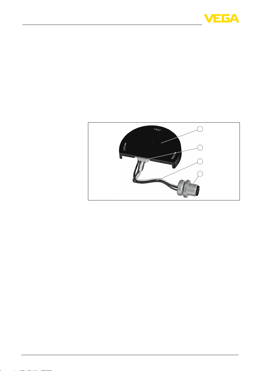
It consists of a contact plate, connection cable with mini plug connector and an M12 x 1 plug.
®
1
2
3
4
Fig. 1: Conguration of DIS-ADAPT
1 Contact plate
2 Mini plug connector
3 Connection cable
4 M12 x 1 plug
The contact plate is inserted into the electronics compartment of the
double chamber housing, the M12 x 1 plug into the housing wall.
This makes it possible to connect a VEGADIS 81 external display and
adjustment unit to the sensor without using the terminals.
The use of a PLICSCOM display and adjustment module in parallel
in the connection compartment is permitted. However, simultaneous
adjustment is not possible.
The housing cover without inspection window still ts on the electronics compartment when DIS-ADAPT is mounted in place.
45250-EN-130625
4
DIS-ADAPT • Adapter for connection of an external display and adjustment unit
Page 5

Tools
3 Mounting
3 Mounting
3.1 Mounting preparations
The following tools are required for mounting:
Spanner SW 17 or hexagon socket size 8 for unscrewing the blind
•
plug
Spanner SW 17 for screwing in the M12 x 1 plug
•
3.2 Mounting steps
Proceed as follows to mount the DIS-ADAPT:
1. Open the cover of the electronics compartment
1
2
Fig. 2: Position of the electronics compartment and the blind plug
1 Electronics compartment
2 Blind plug
2. Unscrew the blind plug on the side of the electronics compartment
3. Loosen the mini plug connector on DIS-ADAPT
4. Insert the plug through the free opening and screw the M12 x 1
plug connector into the housing
5. Connect mini plug connection to DIS-ADAPT
6. Place DIS-ADAPT on the electronics and turn it to the right
45250-EN-130625
DIS-ADAPT • Adapter for connection of an external display and adjustment unit
5
Page 6

3 Mounting
1
2
Fig. 3: Attach the adapter
1 Place
2 Turn
The mounting of DIS-ADAPT is nished.
Removal is carried out in reverse order.
45250-EN-130625
6
DIS-ADAPT • Adapter for connection of an external display and adjustment unit
Page 7

Electronics compartment
Wiring plan
4 Connecting
4 Connecting
1
2
3
Fig. 4: View to the electronics compartment with mounted DIS-ADAPT
1 DISADAPT
2 Internal cable connection
3 Plug connector M12 x 1
34
1
Fig. 5: Top view of the plug connector
1 Pin 1
2 Pin 2
3 Pin 3
4 Pin 4
Contact pin Colour - connection
cable
Pin 1 Brown 5
Pin 2 White 6
Pin 3 Blue 7
Pin 4 Black 8
45250-EN-130625
DIS-ADAPT • Adapter for connection of an external display and adjustment unit
2
Terminal, external display and adjustment
unit
7
Page 8

4 Connecting
Connection example
6
3
4
1
5
Display
2
Fig. 6: Connection example for DIS-ADAPT with external display and adjustment unit
1 Signal cable
2 Sensor
3 DIS-ADAPT
4 Plug connector M12 x 1
5 Assembled cable
6 External display and adjustment unit
45250-EN-130625
8
DIS-ADAPT • Adapter for connection of an external display and adjustment unit
Page 9

5 Supplement
5.1 Technical data
Materials
Contact plate Plastic (PBT)
M12 x 1 plug 316L
Ʋ Seal FKM
Adjustment circuit
Connection to VEGADIS 81
Data transmission digital (I²C-Bus)
Conguration, connection cable 4-wire, screened
Cable length depending on the sensor version
Protection rating
Sensor with connected cable
Ʋ Pressure transmitter IP 66/IP 67
Ʋ Other sensors IP 66/IP 68 (0.2 bar)
5.2 Dimensions DIS-ADAPT
ø 62,5 mm
(2.46")
5 Supplement
8,9 mm
(0.35")
(1.71")
43,5 mm
(3.45")
87,5 mm
M 16x1,5
(0.30")
7,5 mm
M 12x1
(0.43")
11 mm
Fig. 7: Dimensions DIS-ADAPT
45250-EN-130625
DIS-ADAPT • Adapter for connection of an external display and adjustment unit
9
Page 10

Notes
10
45250-EN-130625
DIS-ADAPT • Adapter for connection of an external display and adjustment unit
Page 11

Notes
45250-EN-130625
DIS-ADAPT • Adapter for connection of an external display and adjustment unit
11
Page 12

Printing date:
All statements concerning scope of delivery, application, practical use and operating conditions of the sensors and processing systems correspond to the information
available at the time of printing.
Subject to change without prior notice
© VEGA Grieshaber KG, Schiltach/Germany 2013
VEGA Grieshaber KG
Am Hohenstein 113
77761 Schiltach
Germany
Phone +49 7836 50-0
Fax +49 7836 50-201
E-mail: info.de@vega.com
www.vega.com
45250-EN-130625
 Loading...