

Page 1
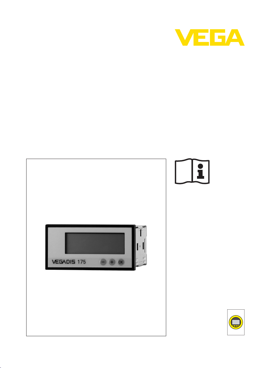
Operating Instruction
VEGADIS 175
s
Document ID:
24386
and
Indication
adjustment
Page 2

Contents
Contents
1 About this
1.1 Function. . . . . . . . . . . . . . . . . . . . . . . . . . . . . . . . . .
1.2 Target group . . . . . . . . . . . . . . . . . . . . . . . . . . . . . .
1.3 Symbolism used . . . . . . . . . . . . . . . . . . . . . . . . . . . .
2 For your safety
2.1 Authorised personnel . . . . . . . . . . . . . . . . . . . . . . . .
2.2 Appropriate use . . . . . . . . . . . . . . . . . . . . . . . . . . . .
2.3 Warning about incorrect use . . . . . . . . . . . . . . . . . . .
2.4 General safety instructions . . . . . . . . . . . . . . . . . . . .
2.5 Safety label on the instrument . . . . . . . . . . . . . . . . . .
2.6 CE conformity . . . . . . . . . . . . . . . . . . . . . . . . . . . . .
2.7 Environmental instructions. . . . . . . . . . . . . . . . . . . . .
3 Product description
3.1 Structure . . . . . . . . . . . . . . . . . . . . . . . . . . . . . . . . .
3.2 Principle of operation . . . . . . . . . . . . . . . . . . . . . . . .
3.3 Operation. . . . . . . . . . . . . . . . . . . . . . . . . . . . . . . . .
3.4 Packaging, transport and storage . . . . . . . . . . . . . . .
4 Mounting
4.1 General instructions . . . . . . . . . . . . . . . . . . . . . . . . .
4.2 Mounting preparations . . . . . . . . . . . . . . . . . . . . . . .
4.3 Mounting steps. . . . . . . . . . . . . . . . . . . . . . . . . . . . .
5 Connect to the signal circuit
5.1 Preparing the connection . . . . . . . . . . . . . . . . . . . . .
5.2 Wiring plan. . . . . . . . . . . . . . . . . . . . . . . . . . . . . . . .
6 Setup
6.1 Indication and adjustment . . . . . . . . . . . . . . . . . . . . .
6.2 Indication scaling . . . . . . . . . . . . . . . . . . . . . . . . . . .
6.3 Operation. . . . . . . . . . . . . . . . . . . . . . . . . . . . . . . . .
document
4
4
4
5
5
5
5
5
5
6
7
7
7
7
9
9
9
10
10
12
14
15
7 Maintenance and fault rectification
7.1 Maintenance . . . . . . . . . . . . . . . . . . . . . . . . . . . . . .
7.2 Remove interferences . . . . . . . . . . . . . . . . . . . . . . . .
7.3 Instrument repair . . . . . . . . . . . . . . . . . . . . . . . . . . .
8 Dismounting
8.1 Dismounting steps . . . . . . . . . . . . . . . . . . . . . . . . . .
8.2 Disposal . . . . . . . . . . . . . . . . . . . . . . . . . . . . . . . . .
9 Supplement
9.1 Technical data . . . . . . . . . . . . . . . . . . . . . . . . . . . . .
9.2 Dimensions . . . . . . . . . . . . . . . . . . . . . . . . . . . . . . .
2 VEGADIS 175
16
16
17
19
19
20
22
24386-EN-120531
Page 3

Contents
Editing status: 2012-05-29
24386-EN-120531
VEGADIS 175 3
Page 4
1 About this document
1 About this document
1.1 Function
is operating instructions manual provides all the information you
Th
need for mounting, connection and setup as well as important
instructions for maintenance and fault rectification. Please read this
information before putting the instrument into operation and keep this
manual accessible in the immediate vicinity of the device.
1.2 Target group
This operating instructions manual is directed to trained qualified
personnel. The contents of this manual should be made available to
these personnel and put into practice by them.
1.3 Symbolism used
Information, tip, note
This
symbol indicates helpful additional information.
Caution: If this
result.
Warning: If this warning is ignored, injury to persons and/or serious
damage to the instrument can result.
Danger: If this warning is ignored, serious injury to persons and/or
destruction of the instrument can result.
applications
Ex
Th
symbol indicates special instructions for Ex applications.
is
l List
The dot set in front indicates a list with no implied sequence.
warning is ignored, faults or malfunctions can
à Action
This a
rrow indicates a single action.
1 Sequence
Numbers set in front indicate successive steps in a procedure.
Battery disposal
symbol characterizes the special information for disposal of
This
batteries and accumulators.
24386-EN-120531
4 VEGADIS 175
Page 5

2 For your safety
2 For your safety
2.1 Auth
All operations described in this operating instructions manual must be
carried out only by trained specialist personnel authorised by the plant
operator.
During work on and with the device the required personal protective
equipment must always be worn.
orised personnel
2.2 Appropriate use
VEGADIS 175 is a digital indicating instrument for 4 … 20 mA circuits.
2.3 Warning about incorrect use
Inappropriate or incorrect use of the instrument can give rise to
application-specific hazards, e.g. vessel overfill or damage to system
components through incorrect mounting or adjustment.
2.4 General safety instructions
This is a high-tech instrument requiring the strict observance of
standard regulations and guidelines. The user must take note of the
safety instructions in this operating instructions manual, the countryspecific installation standards as well as all prevailing safety
regulations and accident prevention rules.
The instrument must only be operated in a technically flawless and
reliable condition. The operator is responsible for trouble-free
operation of the instrument.
During the entire duration of use, the user is obliged to determine the
compliance of the necessary occupational safety measures with the
current valid rules and regulations and also take note of new
regulations.
2.5 Safety label on the instrument
The safety approval markings and safety tips on the device must be
observed.
2.6 CE conformity
The device fulfills the legal requirements of the applicable EC
guidelines. By affixing the CE marking, we confirm successful testing
of the product.
24386-EN-120531
VEGADIS 175 5
Page 6

2 For your safety
The instrument is designed for use in an industrial environment.
Nevertheless, elec
and radiated emissions must be taken into account, as is usual with a
class A instrument according to EN 61326-1. If the instrument is used
in a different environment, its electromagnetic compatibility with other
devices must be ensured by suitable measures.
tromagnetic interference from electrical conductors
2.7 Environmental instructions
Protection of the environment is one of our most important duties. That
is why we have introduced an environment management system with
the goal of continuously improving company environmental protection.
The environment management system is certified according to DIN
EN ISO 14001.
Please help us fulfil this obligation by observing the environmental
instructions in this manual:
l Chapter "Packaging, transport and storage"
l Chapter "Disposal"
6 VEGADIS 175
24386-EN-120531
Page 7

3 Product description
3.1 Structure
3 Product description
Sco
pe of delivery
Application area
Voltage supply
Packaging
e scope of delivery encompasses:
Th
l Digital indicating instrument VEGADIS 175
l Documentation
- this operating instructions manual
- Ex sp ecific safety instructions (with Ex versions), if necessary
further certificates
3.2 Principle of operation
VEGADIS 175 is a digital indicating instrument for measured value
indication in 4 … 20 mA circuits. The measured value is displayed via
the LC display, the digital indication can be scaled. The instrument is
suitabe for front panel mounting.
VEGADIS 175 is looped directly into the 4 … 20 mA circuits and
requires no separate external energy. Connection is carried out via
screw terminals in the housing.
3.3 Operation
Adjustment is carried out via keys in the front plate of the instrument.
3.4 Packaging, transport and storage
Your instrument was protected by packaging during transport. Its
capacity to handle normal loads during transport is assured by a test
according to DIN EN 24180.
The packaging of standard instruments consists of environmentfriendly, recyclable cardboard. For special versions, PE foam or PE foil
is also used. Dispose of the packaging material via specialised
recycling companies.
Transport
Transport inspection
Storage
24386-EN-120531
VEGADIS 175 7
Transport must be carried out under consideration of the notes on the
transport packaging. Nonobservance of these instructions can cause
damage to the device.
The delivery must be checked for completeness and possible transit
damage immediately at receipt. Ascertained transit damage or
concealed defects must be appropriately dealt with.
Up to the time of installation, the packages must be left closed and
stored according to the orientation and storage markings on the
outside.
Page 8

3 Product description
Storage and transport
temperature
Unless otherwise indicated, the p
ackages must be stored only under
the following conditions:
l Not in the open
l Dry and dust free
l Not exposed to corrosive media
l Protected against solar radiation
l Avoiding mechanical shock and vibration
l Storage and transport temperature see chapter "Supplement -
Technical data - Ambient conditions"
l Relative humidity 20 … 85 %
8 VEGADIS 175
24386-EN-120531
Page 9

4 Mounting
92mm (3
5
/
8
")
45 mm
(1
49
/
64
")
92 mm (3
5
/
8
")
4 Mounting
Mountin
g location
Heat effect
4.1 General ins
tructions
Make sure that there are no vibrations in the mounting place.
Protect your instrument against heat, e.g. by other instruments
mounted too close
4.2 Mounting preparations
Required tools:
l Screwdriver for recessed head screws size 2
4.3 Mounting steps
Proceed as follows:
1 Prepare panel cut-out 45 + 0.6 x 92 + 0.8 mm according to
DIN 43700 in compliance with the illustration
2 Insert the instrument with seal from the front into the cut opening
3 Press
the fixing cramps into the respective gaps, hold the
instrument horizontally
4 Tighten the screws of the fixing clasps evenly with a screwdriver
24386-EN-120531
VEGADIS 175 9
Page 10

1 23 4
1
5 Connect to the signal circuit
5 Connect to the signal circuit
safety instructions
Note
Take note of sa-
fety instruction
for Ex applications
Term
inal assignment
5.1 Preparin
g the connection
Always keep in mind the following safety instructions:
l Connect only in the complete absence of line voltage
In hazardous areas you must take note of the respective regulations,
s
conformit
y and type approval certificates of the sensors and power
supply units.
5.2 Wiring plan
Fig. 2: Terminal assignment VEGADIS 175
1 Measuring signal
Terminal
number
1 + Input
2 Internally bridged with terminal4Connection terminal for
3 - Input measuring signal
4 Internally bridged with terminal2Connection terminal for
Polarity Function
measuring signal
4 … 20 mA
additional instrumentation
4 … 20 mA
additional instrumentation
10 VEGADIS 175
24386-EN-120531
Page 11

1
2
3 4
+
–
1
2
1 2 3 4
+
–
–
+
3
1
2
Conne
sensors
5 Connect to the signal circuit
ction to active
Connection to
sensors
passive
Fig. 3: Wiring plan VEGADIS 175 to active
1 To the sensor
2 Internal bridge
Fig. 4: Wiring
1 To the sensor
2 To power supply or the processing system
3 Internal bridge
plan VEGADIS 175 to
sensors
passive
sensors
24386-EN-120531
VEGADIS 175 11
Page 12

VEGADIS 175
OK
3
2
1
6 Setup
6 Setup
ating and adjust-
Indic
ment elements
6.1 Indication
Fig. 5: Adjustment elements of VEGADIS 175
1 LC display
2 Adjustment
3 Selection keys
and adjustment
key
LC display
l Actual measured value (during operation)
l Adjustment values (in the parameter adjustment)
l Dialogue text (in the parameter adjustment)
Adjustment key
l Access to the programming menu
l Selection of adjustment functions within the function group
l Saving of entered data
Selection keys
l Selection of function groups within the menu
l Adjustment of parameters and numerical values (by keeping the
keys permanently pressed, the figures on the display change with
increasing speed)
l When you press the "+/-" key during indication mode, the actual
loop current is displayed
12 VEGADIS 175
24386-EN-120531
Page 13

VEGADIS 175
OK
> 3s
> 3s
+
+
+
-
6
7
1
2
3
4
4
5
OK
OK
OK
OK
OK
+
-
+
-
+
-
Adjus
tment system
6 Setup
Fig. 6: Adjustment system of VEGADIS 175
1 Acc
ess to the adjustment menu
2 Selection of adjustment functions
3 Adjustment of parameters in the editing mode (enter/select data
with "+" or "- " and accept with "OK")
4 Return from the editing mode or the adjustment function in a
function group. By pressing the "+" or " - " keys simultaneously
several times, you reach home position (indication mode).
Beforehand you are asked if the data entered up to that point
should be saved.
5 Direct return to the home position (indication mode). Beforehand
you are asked if the data entered up to that point should be saved.
6 Enquiry of the data memory
7 Select "Yes/No" with the "+" or "- " key and confirm with "OK"
Adjus
tment parameter
24386-EN-120531
VEGADIS 175 13
The following chart shows the adjustment parameters:
Page 14

6 Setup
Decimal
point
Indication value 0 %
Parameter Meaning Adjustment options Factory
dI dP Decimal point: Positions
dI Lo Indication value 0 % to
dI HI Indication value 100 % of
oFFSt Offset: Signal offset for
CodE User code: adjustment
the comma of the
after
numerical indication
the loop current 4 mA
loop current 20 mA
adaptation of the measured value indication
code individually adjustable by the user. An
already assigned user
code can be modified
only if the previous code
for instrument activation
is released. Then the
new code can be modified.
Selection range: 0 up to 4
positions after the decimal point
Value range -19999 up to
99999
Value range -19999 up to
99999
Value range -19999 up to
32567
Value range 0 to 9999.
Note: No user code is
active with 0.
settings
9999.9
0.0
100.0
0.0
0
6.2 Indication scaling
1 Push the "OK" key longer than three seconds to get to the
adjustment menu. The display shows: "dI dP"
2 Move the decimal point to the requested position by using the "+/
–" keys
3 Accept the modified value by pushing the "OK" key longer than 3
seconds: the display shows "SA UE ?"
4 Select "yes" or "no" with the "+/-" keys
5 Terminate with the "OK" key. When "yes" is selected the modified
value is saved, when "no" is selected the value is discarded.
1 Push the "OK" key longer than three seconds to get to the
adjustment menu. The display shows again: "dI dP"
2 Push the "OK" key briefly once to reach the menu item "dI Lo"
3 Set the requested indication value for 4 mA with the "+/–" keys
4 Accept the modified value by pushing the "OK" key longer than 3
seconds: the display shows again "SA UE ?"
5 Select "yes" or "no" with the "+/-" keys
6 Terminate with the "OK" key. When "yes" is selected the modified
value is saved, when "no" is selected the value is discarded.
The parameter adjustment of the indication value 0 % is finished. The
actual measured value is then displayed.
24386-EN-120531
14 VEGADIS 175
Page 15

6 Setup
ation value 100 %
Indic
Offset
1 Push the "OK" key
longer than three seconds to get to the
adjustment menu. The display shows again: "dI dP"
2 Push the "OK" key briefly twice to reach the menu item "dI Hi"
3 Set the requested indication value for 20 mA with the "+/–" keys
4 Accept or discard like with indication value 0 %
The adjustment of the indication value 100 % is finished. The actual
measured value is then displayed.
1 Push the "OK" key longer than three seconds to get to the
adjustment menu. The display shows again: "dI dP"
2 Push the "OK" key briefly three times to reach the menu item
"oFFST"
3 Set the requested offset value with the "+/–" keys
4 Accept or discard like with indication value 0 %
The parameter adjustment of the offset is finished. The actual
measured value is then displayed.
Tip:
The
previously described menu items can also be completed one after
the other and saved all at once. Press the "OK" key only very briefly
after the parameter adjustment of a menu item. By doing this, you
reach the next menu item for which you can carry out the parameter
adjustment as described above.
6.3 Operation
Adjustment or process errors are immediately signalled in the display.
Messages to be acknowledged are immediately deleted after key
pressing.
Syste
m messages
Indication Cause Rectification
"∏∏∏∏" Measuring range underrun.
"UUUU" Measuring range exceeded.
"SA UE ?" Adjustment parameters were
"SA UE ?" fla-
shing
There is an input signal
≤ 3.6 mA on the analogue
input.
There is aninputsignal ≥ 21 mA
on the analogue input.
modified. The instrument asks
for release to save.
After a change of the adjustment parameters, the instrument saves them in the
EEPROM.
Check input signal
Check input signal
Release or unrelease with the
"+/–" keys and save with the
"OK" key or discard.
After saving, the instrument
displays the measured value.
24386-EN-120531
VEGADIS 175 15
Page 16

7 Maintenance and fault rectificati
7 Maintenance and fault rectification
on
ilure reasons
Fa
Fault rectificat
Check the 4 … 20 mA
signal
ion
7.1 Maintena
If the instrument is used properly, no special maintenance is required
in normal operation.
nce
7.2 Remove interferences
VEGADIS 175 offers maximum reliability. Nevertheless, faults can
occur during operation. These may be caused by the following, e.g.:
l Sensor
l Process
l Voltage supply
l Signal processing
The first measure is to check the sensor output signal according to the
operating instructions manual of the respective sensor. In many cases
the reasons can be determined this way and faults rectified. System
errors of VEGADIS 175 are displayed via the system error message of
the following chart:
Connect a handheld multimeter in the suitable measuring range
according to the wiring plan.
? 4 … 20 mA signal missing
l Wrong connection to voltage supply
à Check and correct, if necessary, according to chapter "Wiring
plan"
l No power supply
à Check cables for breaks; repair if necessary
l Operating voltage too low or load resistance too high
à Check, adapt if necessary
In Ex applications, the regu
circuits must be observed.
System erro
16 VEGADIS 175
r message
Errors occurring during the self-test or operation are immediately
shown on the display. Messages to be acknowledged are immediately
deleted after key pressing.
lations for the wiring of intrinsically safe
24386-EN-120531
Page 17

7 Maintenance and fault rectificati
Error code Cause Rectification
E090 Loop current
save the adjustment data,
there must be at least 3.6 mA
on the input.
E101 The EEPROM for saving the
adjustment parameters is defective.
E102 Checksum of the adjustment
parameters is not valid or the
software version in the EE-
PROM does not correspond
with the adjustment data in the
EEPROM. P ossible cause is a
failure of the operating voltage
during parameter storage.
E103 Checksum in the EEPROM on
the calibration values of the
analogue input is wrong. Possible reason is a failure of the
supply voltage during calibration, a non-adjusted instrument
or a defective EEPROM.
E106 Warning: Due to a programm-
ing error, an incorrect setting
of the indicating range/scaling
was carried out (lower and
upper value are unequal).
E111 Checksum in the EEPROM on
the adjustment values of the
analogue input is wrong. Possible reason is a failure of the
supply voltage while parameters were being saved.
too small. To
Check measurement loop
Repair instrument
By acknowledging with the
"OK" key, a reset is carried out
automatically, i.e. all
parameters are reset to
default.
Repair instrument
Correct adjustment values
Repair instrument
on
r service hotline
24 hou
Should these measures not be successful, please call in urgent cases
the VEGA service hotline under the phone no. +49 1805 858550.
The hotline is available to you 7 days a week round-the-clock. Since
we offer this service world-wide, the support is only available in the
English language. The service is free of charge, only the standard
telephone costs will be charged.
Reaction after fault rectification
Depending on the reason for the fault and the measures taken, the
steps described in chapter "Set up" may have to be carried out again.
7.3 Instrument repair
If a repair is necessary, please proceed as follows:
24386-EN-120531
VEGADIS 175 17
Page 18

7 Maintenance and fault rectificati
on
You can download a return form (23 KB) from our Intern
et homepage
www.vega.com under: "Downloads - Forms and certificates - Repair
form".
By doing this you help us carry out the repair quickly and without
having to call back for needed information.
l Print and fill out one form per instrument
l Clean the instrument and pack it damage-proof
l Attach the completed form and, if need be, also a safety data
sheet outside on the packaging
l Please ask the agency serving you for the address of your return
shipment. You can find the respective contact data on our website
www.vega.com under: "Compa
ny - VEGA worldwide"
18 VEGADIS 175
24386-EN-120531
Page 19

8 Dismounting
8 Dismounting
8.1 Dism
Take note of chapters "Mounting" and "Connecting to power supply"
and carry out the listed steps in reverse order.
ounting steps
8.2 Disposal
The indicating and adjustment module consists of materials which can
recycled by specialised recycling companies. We have purposely
designed the components to be easily separable.
WEEE directive 2002/96/EG
This indicating and adjustment module is not subject to the WEEE
directive 2002/96/EG and the respective national laws (in Germany, e.
g. ElektroG). Pass the indicating and adjustment module directly on to
a specialised recycling company and do not use the municipal
collecting points. These may only be used for privately used products
according to the WEEE directive.
Correct disposal avoids negative effects on humans and the environment and ensures recycling of useful raw materials.
Materials: see chapter "Technical data"
If you have no way to dispose of the old instrument properly, please
contact us concerning return and disposal.
24386-EN-120531
VEGADIS 175 19
Page 20

9 Supplement
9 Supplement
9.1 Technical
General data
Materials
- Housing front Aluminium die-casting
- Housing Sheet steel galvanized
- Rear of the housing plastic ABS
- Inspection window of the indication
Installation position no limitations
Weight approx. 0.3 kg (0.661 lbs)
Ambient conditions
Ambient temperature -10 … +60 °C (14 … +140 °F)
Storage and transport temperature -25 … +70 °C (-13 … +158 °F)
Climatic class Class B 2 according to EN 60 654-1
Electromechanical data
Screw terminals for cable cross-section up to
- massive 1.5 mm² (AWG 15)
- Stranded wire with end sleeve 1.0 mm² (AWG 18)
Indicating and adjustment elements
Indication LC display, 5-digit
Height of figures 17 mm
Indication range -199999 up to +999999
Adjustment elements 3 keys (-/+/E)
data
Circuit
Range 4 … 20 mA
Input current max. 150 mA
HART signal is transmitted
Voltage supply
Operating voltage via 4 … 20 mA current
loop
Voltage loss 2 V
Load see diagram in the operating instructions manual of
20 VEGADIS 175
12 … 36 V DC
the respective sensor
24386-EN-120531
Page 21

9 Supplement
Deviation
Current mea
final value
Temperature drift < 0.1 %/10 K
Electrical protective measures
Protection rating
- between front frame and front panel IP 65
- Terminals IP 20
ESD according to IEC 61000-4-2 6 kV/8 kV
Electromagnetic fields according to
IEC 61000-4-3
Burst (supply) according to IEC 61000-4-4 2 kV
Surge according to IEC 61000-4-5 1 kV
Conducted high frequency according to
EN 61000-4-6
Approvals
Instruments with approvals can have different technical data depending on the version.
That's why the associated approval documents of these instruments have to be carefully noted.
They are part of the delivery or can be downloaded under
"serial number search" as well as via "Downloads" and "Approvals".
surement error, referring to the
< 0.1 %
10 V/m
10 V
www.vega.com via "VEGA
Tools" and
24386-EN-120531
VEGADIS 175 21
Page 22

12 3 4
-
+
OK
VEGADIS 175
96 mm (3
25
/
32
")
48 mm
(1
57
/
64
")
91 mm (3
37
/
64
")
91 mm (3
37
/
64
")
80 mm (3
5
/
32
")9,5 mm
(
3
/
8
")
6 mm
(
15
/
64
")
43 mm
(1
11
/
16
")
9 Supplement
9.2 Dimensions
DIS 175
VEGA
Fig. 7: VEGADIS 175
22 VEGADIS 175
24386-EN-120531
Page 23

9.3 Industrial property rights
9 Supplement
VEGA produc
Further information see http://www.vega.com.
Only in U.S.A.: Further information see patent label at the sensor
housing.
VEGA Produktfamilien sind weltweit geschützt durch gewerbliche
Schutzrechte.
Nähere Informationen unter http://www.vega.com.
Les lignes de produits VEGA sont globalement protégées par des
droits de propriété intellectuelle.
Pour plus d'informations, on pourra se référer au site http://www.vega.
com.
VEGA lineas de productos están protegidas por los derechos en el
campo de la propiedad industrial.
Para mayor información revise la pagina web http://www.vega.com.
Линии продукции фирмы ВЕГА защищаются по всему миру
правами на интеллектуальную собственность.
Дальнейшую информацию смотрите на сайте http://www.vega.com.
VEGA系列产品在全球享有知识产权保护。
进一步信息请参见网站<http://www.vega.com>。
t lines are global protected by industrial property rights.
9.4 Trademark
All the brands as well as trade and company names used are property
of their lawful proprietor/originator.
24386-EN-120531
VEGADIS 175 23
Page 24

VEGA Grieshaber KG
ISO 9001
Am Hohenstein 113
77761 Schiltach
Germany
Phone +49 7836 50-0
Fax +49 7836 50-201
E-mail: info.de@vega.com
www.vega.com
Printing date:
All statements concerning scope of delivery, application,
practical use
and operating conditions of the sensors and
processing systems correspond to the information avail-
able at the time of printing.
© VEGA Grieshaber KG, Schiltach/Germany 2012
Subject to change without prior notice 24386-EN-120531
 Loading...