

Page 1
Operating Instructions
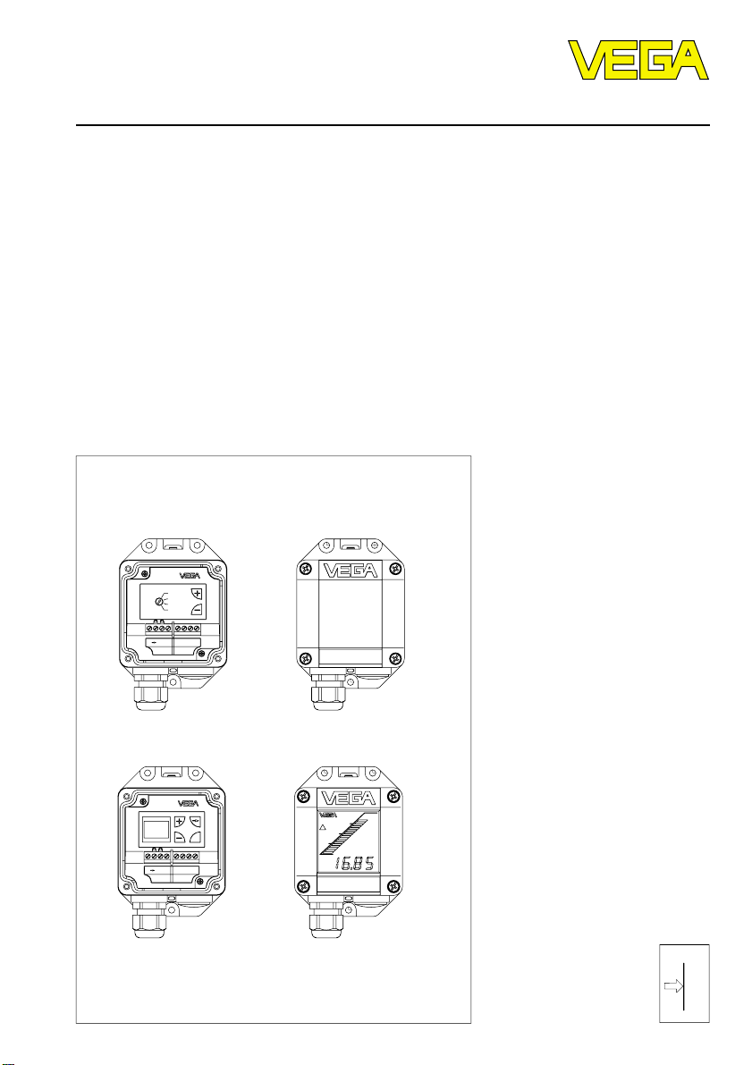
VEGADIS 10
OPERATE
t
i
ZERO
SPAN
Level and Pressure
BAR DISPLAY
DISPLAYBAR
E01
OK
E01
p
Page 2

Contents
Safety information ........................................................................ 2
Note Ex-area ................................................................................ 2
1 Product description
1.1 Function and configuration .................................................. 3
1.2 Types and versions ............................................................. 3
1.3 Approvals ............................................................................. 3
1.4 Technical data ....................................................................... 4
1.4 Dimensions ........................................................................... 5
2 Mounting..................................................................................... 5
3 Electrical connection
3.1 Connection instructions ....................................................... 6
3.2 Connection plan ................................................................... 6
4 Set-up .......................................................................................... 6
Contents
5 Instrument modification
5.1 Exchange of adjustment modules ...................................... 7
Safety information
The described module must only be installed
and operated as described in these operating
instructions. Please note that other action can
cause damage for which VEGA does not take
responsibility.
2 VEGADIS 10
Note Ex-area
Please note the approval documents attached
(yellow binder), and especially the included
safety data sheet.
Page 3
Product description
1 Product description
1.1 Function and configuration
VEGADIS 10 is an indicating and adjustment
instrument for VEGABAR process pressure
transmitters. VEGADIS 10 is connected to
VEGABAR with a 4-wire standard cable up to
25 m long. An additional supply voltage for
VEGADIS 10 is not required.
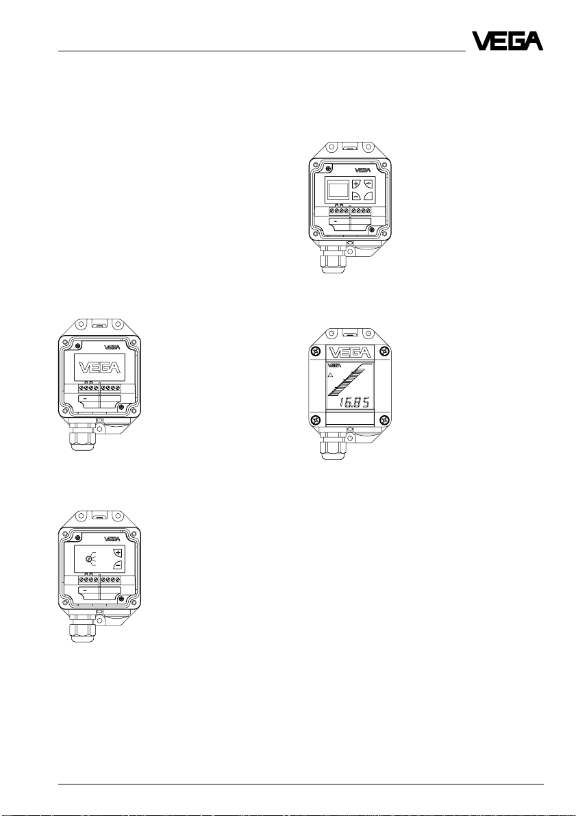
1.2 T ypes and versions
without adjustment (only as indicating
instrument)
BAR
DISPLAY
E01
Adjustment of the basic functions
Menu-guided adjustment of additional
functions
OK
BAR DISPLAY
E01
Version with indicating module
1.3 Approvals
CENELEC EEx ia IIC, PTB-no. Ex-94.C.4071
GL (German Lloyd), no. 96 708-95 HH
OPERATE
t
i
ZERO
SPAN
DISPLAYBAR
E01
Approved versions should be used, if
VEGADIS 10 is used in hazardous areas.
For these applications, the appropriate official
documents (test reports, test certificates and
conformity certificates) should be noted.
These are supplied with the appropriate
instrument.
VEGADIS 10 3
Page 4

Product description
1.4 T echnical data
General
Housing material plastic PBT
Indication window glass
Breather facility PTFE filter element
Weight approx. 0,35 kg
Adjustment and indicating instrument
Adjustment of the basic functions 2 keys, 1 rotating switch
Menu-guided adjustment
with additional function
- adjustment elements 4 keys
- indicating elements DOT-matrix display, 3 lines with 7 figur es each
Indicating module LC display with
- bar graph (20 segments)
- digital value (4 digits)
- tendency indicators for increasing or
falling values
Connection
Cable entry PG 13,5 (for cable ø 5 … 10 mm)
Screw terminals for cross-section area of conductor up to
2,5 mm
2
Adjustment circuit
Connection to VEGABAR process pressure transmitters
Connection line 4-wire (standard line)
Cable length max. 25 m
1)
Ambient conditions
Ambient temperature
- VEGADIS 10 -40°C … +85°C
- indicating module -20°C … +70°C
Storage and transport temperature -40°C … +85°C
Electrical protective measures
Protection
2)
IP 65
CE-conformity
VEGADIS 10 meets the protective regulations of EMVG (89/336/EWG) and NSR
(73/23/EWG). The conformity has been judged acc. to the following standards:
EMVG Emission EN 50 081 - 1:
Susceptibility EN 50 082 - 2:
NSR EN 61 010 - 1:
1)
Air permeable and moisture blocking
2)
For maintaining housing protection, use of a suitable seal for the cable in the PG is necessary. If the seal
used does not match the cable, it should be replaced by a suitable one.
4 VEGADIS 10
Page 5

Product descrip tion, mountin g
1.4 Dimensions
without indication
38 72
5
118
108
135
Pg 13,5
2 Mounting
VEGADIS 10 can be mounted as follows:
- on carrier rail 35 x 7,5 acc. to EN 50 022
- on mounting sheet or on the wa ll.
with indication
82
85
VEGADIS 10 5
Page 6

3 Electrical connection
Electrical connection, set-up
3.1 Connection instructions
VEGADIS 10 can be connected to VEGABAR
process pressure transmitters with a 4-wire
Note:
Before starting connection, switc h off the
power supply of all components.
standard cable (max. length 25 m). An exter nal energy sour ce is not necessar y.
Screened cable is re commended, if strong
electromagnetic interferences are expected.
Screening should be carried out from one
sensor end.
3.2 Connection plan
VEGABAR VEGADIS 10 (with or without indication)
8765321 87654321
–+
External energy
12 … 36 V DC
4 … 20 mA
max. 25 m
4 Set-up
Loosen the four screws on the upper side of
VEGADIS 10 and remove the housing cover
or the indicating module.
Adjustment module
OK
Connection and adjustment of VEGADIS 10
can be facilitated by lossely fastening the
housing cover or the indicating module with
two of t he screws laterally or dis placed to the
bottom.
The set-up and adj ustment of the VEGABAR
process pressure transmitter by means of
VEGADIS 10 corresponds exactly to the
procedure directly on VEGABAR (see oper ating instructions VEGABAR…).
Furthermore, the different electronic versions
of VEGADIS 10 correspond to the electr onic
versions of VEGABAR.
Electronics B:
VEGADIS is only used as indicating instrument.
Electronics C:
Tighten the screws
Adjustment of the basic functions
Electronics D:
Menu-guided adjustment with additional
functions
6 VEGADIS 10
Page 7

Instrument modification
5 Instrument modification
5.1 Exchange of adjustment
modules
Indicating
module with
LC display
Module for
basic
functions
Module for
menu-guided
adjustment
VEGADIS 10
Adjustment modules
The modular construction of VEGADIS 10
ensures that adjustment modules a nd the
indicating module can be retrofitted, exchanged or removed.
The connection of the modules is made:
- on the adjustment module via 4-pole plug
connection
- on the indicating module via screw terminals.
Module without
adjustment
Removal of an adjustment module
1 Separate VEGABAR from voltage supply
(if VEGADIS 10 i s already connected to
VEGABAR)
2 Loosen screws on cover of VEGADIS 10
3 Loosen connection cable from the te rmi-
nals
4 Loosen screws of the adjustment module
5 Detach the adjustment module and re-
move the plug connection
Addition of an adjustment module
6 Plug the plug connection of the new ad-
justment module to the plug-in socket
7 Screw on the new adjustment module
8 Connect the connection cables to termi-
nals
9 Close cover of VEGADIS 10
10 If necessary, reconnect VEGABAR to
voltage supply
Indicating modules
Retrofitting of an indicating module
1 Separate VEGABAR from voltage supply
(if VEGADIS 10 i s already connected to
VEGABAR)
2 Loosen the screws on the cover of
VEGADIS 10
3 Remove cover
4 Connect indicating module to the screw
terminals via the four cables (see "3.2
Connection plan“)
Note:
Step 4 will be easier if the indicating module
is temporarily loosely fastened (displaced)
using two screws.
5 Place the indicating module on VEGADIS
10 in the correct position
6 Tighten the screws of the cover
7 If nec essary, reconnect VEGABAR to
voltage supply
VEGADIS 10 7
Page 8

VEGA Grieshaber KG
Am Hohenstein 113
D-77761 Schiltach
Phone (0 78 36) 50 - 0
Fax (0 78 36) 50 - 201
e-mail info@vega-g.de
ISO 9001
The statements on types, application, use and operating conditions
of the sensors and processing systems correspond to the actual
knowledge at the date of printing.
Technical data subject to alteration.
2.23 451 / July ’99
 Loading...