


T
ECHNICAL INSTALLATION
M
ANUAL
UNDERGROUND OPERATOR
FOR SWINGING GATES AND DOORS
WARNING!!
Before installing, thoroughly read this manual that is an integral part of
the pack
The CE mark conforms to European directive EEC 89/336 + 92/31 + 93/68
UNDER 250

2
INDEX
1 PACKING CONTENTS ............................................................3
2 VIEW OF TYPICAL AUTOMATION AND NAMES OF
COMPONENTS........................................................................4
3 TECHNICAL DATA..................................................................5
4 DIMENSIONS...........................................................................6
5 TYPICAL CONNECTION AND CABLE SECTION..................6
6 INSTALLATION .......................................................................7
6.1 GATE WING OPENING ANGLE ......................................................................................................... 7
6.2 BOX INSTALLATION PROCEDURE ...................................................................................................8
6.3 ASSEMBLING THE OPERATOR AND LEVERS................................................................................. 9
6.4 FASTENING THE OPERATOR LEVER TO THE GATE.................................................................... 10
6.5 EMERGENCY RELEASE PROCEDURE........................................................................................... 10
7 TROUBLESHOOTING...........................................................11

3
1 PACKING CONTENTS
This Kit contains the following items:
1 Underground operator
1 Foundation box
1 Lever kit for 90° opening
1 Release lever
Optional accessories
1 Remote control
1 Tuned antenna 433.920
1 Pair of outdoor photocells
1 Flashing light 230V
1 Outdoor key-switch
1 Sign

4
2 VIEW OF TYPICAL AUTOMATION AND NAMES OF COMPONENTS
Optimal installation
1. Operators
2. Electronic control unit
3. External photocell
Internal photocell (optional)
4. Flashing warning light
5. Key-switch
6. Antenna
7. Remote control

5
3 TECHNICAL DATA
UNDER 250 (230VAC)
Max. weight per wing 500 Kg
Max. width per wing 2,5 m
Motors power supply 230 V ± 10%, 50 Hz
Condenser 10 µF
Motor current input 1.2 – 1.6 A
Motor power 200W
Overload cutout 135°C
Torque given 250 Nm
Operator weight 10 Kg
Noise level < 30 dB
Protection rating IP 67
Opening time 90° 16 sec.
Mechanical release for emergency manoeuvre With toothed lever provided
Working temperature -20° C / + 55° C
UNDER 250 (24VDC)
Max. weight per wing 500 Kg
Max. width per wing 2,5 m
Motors power supply 24VDC
Motor current input 2,7 A
Motor power 60W
Torque given 200 Nm
Operator weight 10 Kg
Noise level < 30 dB
Protection rating IP 67
Opening time 90° 16 sec.
Mechanical release for emergency manoeuvre With toothed lever provided
Working temperature -20° C / + 55° C

6
4 DIMENSIONS
5 TYPICAL CONNECTION AND CABLE SECTION
2 x 0.75 mm2
RX
Photocell
TX Photocell
3 x 1.5 mm2
4 x 0.75 mm2
2 x 0.75 mm2
4 x 1.5 mm2
4 x 1.5 mm2
230V line

7
CONSIDERATIONS FOR INSTALLATION
• The installation and testing operations must be performed solely by qualified personnel in order to
guarantee the proper and safe operation of the automatic gate.
• The company declines any responsibility for damage caused by incorrect installations due to
incompetence and/or negligence.
• Before assembling the automatism, check that the gate is in perfect working order, hangs well on its
hinges and is suitably lubricated. It must also comply with the safety standards in force in the country of
installation.
6 INSTALLATION
Introductory note: Dig a hole big enough to hold the foundation box, calculate the required opening angle,
insert the sheath for laying the power cable and that for laying the limit switch cables (where applicable),
make water drainage holes in the ground and cement the box solidly.
6.1 GATE WING OPENING ANGLE
6.1.1 Establish the required opening angle
Internal view
Pillar
Box
position
Internal view
Box
position
Pillar

8
6.2 BOX INSTALLATION PROCEDURE
6.2.1 Dig a hole big enough to hold the box
containing the operator (see F1)
6.2.2 Insert the tubes for water drainage in the
prepared holes (F1C)
6.2.3 Insert the sheath for laying the power
cables and limit switch (F1D).
Note: while positioning the box, keep in mind
the minimum distance there must be between
the pillar and the centre of rotation of the gate
hinge. (see F2)
Cement so that the box cannot be moved,
wait for it to dry and then assemble the
operator and levers.
Distance between Pillar - Hinge Centre
Distance between
Pillar - Hinge Centre
9
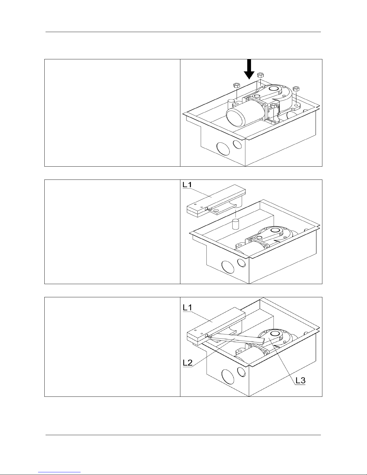
6.3 ASSEMBLING THE OPERATOR AND LEVERS
6.3.1 Place the operator in the box and fasten it
with the nuts provided.
6.3.2 Insert the ball in the pin located on the box
and fit the gate anchorage lever (L1)
6.3.3 Insert the lever (L3) onto the motor shaft
6.3.4 Fit the connecting lever (L2)
F3
F4
F5

10
6.4 FASTENING THE OPERATOR LEVER TO THE GATE
6.4.1 Insert the cover and fasten it with the screws
provided
View
6.4.2 Position the gate wing and the lever (L1) so
that they are perfectly aligned and fasten
them by welding or similar.
6.5 EMERGENCY RELEASE PROCEDURE
• Insert the key CHS provided into the appropriate
hole (V) on the lever L1 (see Fig.).
• Turn the key clockwise by about 45°
F6
F7
F8
F9

11
7 TROUBLESHOOTING
PROBLEM PROBABLE CAUSE REMEDY
230 volt mains voltage absent Check master switch
Emergency STOP present
Check for any STP selectors or
commands.
If not used, check jumper on STP
contact input on unit
Fuse blown Replace with one of same value.
Power cable of motor or motors not
connected or faulty.
Connect the cable to appropriate
terminal or replace.
On giving a command with the remote
control or with the key-switch, the gate
opens or the motor does not start
There is a blockage in the photocell or
it is not working
Check the connection, remove any
obstacle.
On giving a command with the remote
control, the gate does not open but
works with the key command
The remote control has not been
memorised or the battery is flat
Carry out the remote control
recognition procedure on the radio
receiver or replace the battery with a
new one.
On giving a command, the flashing
warning light works slowly and the light
is dim
2 A fuse blown Replace with one of same value
The gate starts, but then stops
The force of the motor or motors is
insufficient
Modify the value with the FORCE
trimmer on the control unit
There is an obstacle in front of the
wings, the hinges are blocked or the
motor anchorage bracket or brackets
have come loose
Remove the obstacle from in front of
the wings, restore the hinges, replace
or lubricate them.
Fasten the motor bracket
On giving a command, the motor
starts, but the gate does not move
The
electric lock, if present, does
not work
Check if it is connected or lubricate
One wing opens and the other closes The connection is not correct
Invert the cable polarity of motor in
question
N.B. - If the problem persists, contact your Retailer or the nearest Service Centre

SAFETY PRECAUTIONS
These warnings are an essential, integral part of the product and must be given to the user. They provide
important indications on the installation, use and maintenance and must be read carefully. This form must be
preserved and passed on to subsequent users of the system. The incorrect installation or improper use of
the product may be dangerous.
INSTALLATION INSTRUCTIONS
•
The installation must be performed by professionally skilled personnel and in compliance with current
local, state, national and European legislation.
•
Before beginning the installation, check the integrity of the product.
•
The laying of cables, electrical connections and adjustments must be workmanlike performed.
•
The packing materials (cardboard, plastic, polystyrene, etc.) are a potential hazard and should be
disposed of correctly and not left within reach of children.
•
Do not install the product in potentially explosive environments or environments disturbed by
electromagnetic fields. The presence of inflammable gases or fumes is a grave danger to safety.
•
Set up a safety device for overvoltage, a disconnecting and/or differential switch suitable for the product
and conforming to current standards.
•
The manufacturer declines any and all responsibility for product integrity, safety and operation in the
event incompatible devices and/or components are installed.
•
Solely original spare parts should be used for repairs and replacements.
•
The installer must provide all the information relating to the operation, maintenance and use of the
individual parts, components and system as a whole.
MAINTENANCE
•
To ensure product efficiency, it is essential that professionally skilled personnel carry out maintenance
within the times established by the installer, the manufacturer and by current legislation.
•
All installation, maintenance, repairs and cleaning operations must be documented. This documentation
must be preserved by the user, and made available to the personnel responsible.
WARNINGS FOR THE USER
•
Read the instructions and enclosed documentation carefully.
•
The product must be used for the express purpose for which it was designed. Any other use is
considered improper and therefore hazardous. In addition, the information given in this document and in
the enclosed documentation may be subject to modifications without prior notice. It is given as an
indication only for product application. The company declines any responsibility for the above.
•
Keep products, devices, documentation and anything else provided out of reach of children.
•
In the event of maintenance, cleaning, breakdown or faulty operation of the product, cut off the power
and do not attempt to operate on the product. Contact solely the professionally skilled personnel
responsible for these operations. Failure to adhere to the above indications may be dangerous.
WARRANTY LIMITS
The 24-month warranty starting from the date printed on the product is valid only for the first purchaser.
It does not cover the following eventualities: negligence, incorrect or improper use of the product, use of
accessories not conforming to the manufacturer's specifications, tampering by the customer or third parties,
natural causes (lightning, floods, fire, etc.), riots, vandalism, modifications to the environmental conditions of
the installation site. Nor does the warranty cover parts subject to wear (batteries, etc..). The product is to be
returned for repair carriage free. The company shall return the repaired product to the sender carriage
forward. Otherwise, the goods shall be rejected on arrival or withheld at dispatch. The purchase of the
product implies full acceptance of all warranty conditions.

1095 Budapest, Mester u. 34.
Tel.: *218-5542, 215-9771, 215-7550,
216-7017, 216-7018 Fax: 218-5542
Mobil: 30 940-1970, 20 949-2688
1141 Budapest, Fogarasi út 77.
Tel.: *220-7940, 220-7814, 220-7959,
220-8881, 364-3428 Fax: 220-7940
E-mail: delton@delton.hu Web: www.delton.hu
www.kaputnyitunk.hu
Mobil: 30 531-5454, 30 939-9989
 Loading...