


Electronic control board for sectional door operator
AT 7070
WARNING!! Before installing, thoroughly read this manual that is an integral part of the pack
Our products if installed by qualified personnel capable to evaluate risks, comply with norms UNI EN 12453, EN 12445
The CE mark conforms to European directive EEC 89/336 + 92/31 + 93/68 D.L. 04/12/1992 N. 476.

LAY OUT
|
|
|
|
|
|
|
|
|
RF CODE |
CLOSE |
|
OPEN |
PROG |
|
|
|
|
|
8 |
7 |
6 |
5 |
4 |
3 |
2 |
1 |
|
|
|
|
|
|
|
|
|
|
|
|
|
|
|
|
|
|
ON |
|
|
|
|
|
|
|
|
|
|
|
|
|
|
|
|
|
|
|
|
1 |
|
2 |
|
3 |
4 |
|
|
|
|
|
|
|
|
|
|
|
POWER |
SPEEDSLOW |
|
LED |
|
|
|
|
||||
|
|
|
|
|
|
|
|
|
|
|
|
|
|
|||||
|
|
|
|
|
|
+ |
|
+ |
|
|
|
|
|
|
|
|
||
|
|
|
|
|
|
|
|
TR1 |
TR2 |
|
|
|
|
|
|
|
||
LED |
|
|
|
|
|
|
|
|
|
|
|
|
|
|
|
|
||
10 |
|
|
|
|
|
|
|
|
|
|
|
|
|
|
|
|
|
|
|
|
|
|
|
5 |
|
6 |
7 |
LED |
8 |
9 |
|
|
|
|
|
LED |
|
|
|
|
|
|
|
|
|
|
|
|
|
10 |
|
|||||
|
ANT |
|
COM |
|
START |
|
PHOTO |
STOP |
COM |
FCC |
FCA |
COM |
+12V |
LAMP |
MOTOR - |
SIG +5 |
24Vac |
|
|
|
|
|
RELAY |
||||||||||||||
|
1 |
|
2 |
|
3 |
|
4 |
5 |
6 |
7 |
8 |
9 10 |
12 |
|
14 |
16 |
18 |
|
|
|
|
|
|
|
|
|
|
|
|
|
|
11 |
13 |
15 |
17 |
19 |
|
ELECTRICAL CONNECTION
1 |
Antenna |
|
||
2 |
Start-stop-photocell common contact |
1 mm² |
||
3 |
Start contact N.O. |
1 mm² |
||
4 |
Photocell contact N. C. (put a jumper if nor used) |
1 mm² |
||
5 |
Stop contact N. C. (put a jumper if nor used) |
1 mm² |
||
6 |
Limit switches common contact |
1 mm² |
||
7 |
Closure limit switch contact N.C. (put a jumper if nor used) |
1 mm² |
||
8 |
Opening limit switch contact N.C. (put a jumper if nor used) |
1 mm² |
||
9 |
Accessory power supply common |
1 mm² |
||
10 |
+ 12Vdc accessory power supply (photocells) |
1 mm² |
||
11-12 |
Flashing light free contact |
|
|
1 mm² |
|
||||
13-14 |
Motor connection 24 Vdc |
1 mm² |
||
15 |
Encoder connection Negative |
1 mm² |
||
16 |
Encoder connection signal |
1 mm² |
||
17 |
Encoder connection +5V |
1 mm² |
||
18-19 |
Power Input 24 Vac (Transformer) |
1,5 mm² |
||
N.O. = Normally Open Contact |
N.C. = Normally Closed Contact |
LED MEANINGS TABLE
N° LED |
DESCRIPTION |
|
N° LED |
DESCRIPTION |
1 |
RADIO |
|
6 |
PHOTOCELL |
2 |
CLOSE |
|
7 |
STOP |
3 |
OPEN |
|
8 |
CLOSURE LIMIT SWITCH |
4 |
PROGRAMMING |
|
9 |
OPENING LIMIT SWITCH |
5 |
START |
|
10 |
COURTESY LIGHT |
ON ON ON ON ON ON ON ON
DIP SWITCHES FUNCTIONS
1 2 3 4 5 6 7 8
DIP 1 |
AUTOMATIC CLOSING: |
||||
ON |
Door closes automatically after waiting the a.c. time. |
||||
OFF |
Door does not close automatically. |
||||
DIP 4 |
SAFETY FUNCTION (photocell): |
||||
ON |
ANALOG Contact (8.2KΩ) |
|
|
||
|
|||||
OFF |
N.C Contact (put a jumper if not used) |
|
|
|
|
|
|
|
|||
DIP 5 |
COURTESY LIGHT (LED 10): |
||||
ON |
Switched off |
||||
OFF |
Switched on (with sthe START command, LED work for 30 sec) |
||||
DIP 6 |
FLASHING LIGHT OUTPUT (LAMP RELAY): |
||||
ON |
Light blinks until the operator is running or waiting for automatic closing. |
||||
|
It turns off after 30 seconds the operator stop. |
||||
OFF |
Light is fix until the operator is running or waiting for automatic closing. |
||||
|
It turns off after 30 seconds the operator stop |
||||
DIP 7 |
SLOW START CLOSING |
||||
ON The automation during closing start at slow speed. |
|||||
OFF |
The automation during closing start at normal speed. |
||||
DIP 8 OPERATOR RUNNING DIRECTION: |
|||||
ON |
Normale polarity |
||||
OFF |
Reversed polarity |
||||
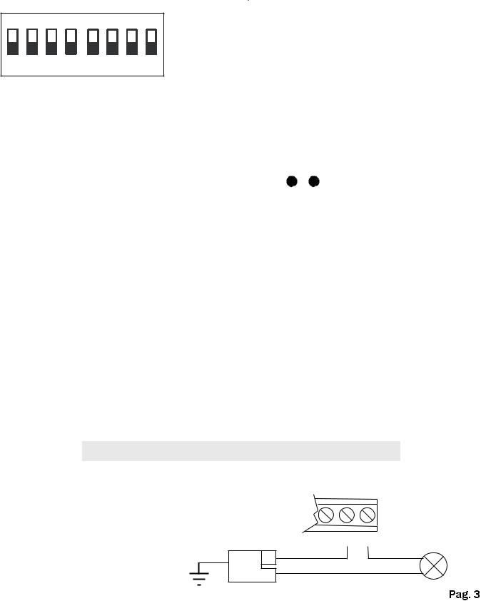
FLASHING LIGHT CONNECTION
Flashing light output relay (terminals 11-12)
Ground Power supply L
230V N
+12V
LAMP
RELAY
11 12 |
LAMP |
230V |
 Loading...