


Italiano
PH - PH1
Istruzioni per l’installazione
Installation instructions Instructions pour l’installation Installationsanleitung Instrucciones para la instalación
SCOPO DEL MANUALE
Questo manuale è stato redatto dal costruttore ed è parte integrante del prodotto.
In esso sono contenute tutte le informazioni necessarie per:
•la corretta sensibilizzazione degli installatori alle problematiche della sicurezza;
•la corretta installazione del dispositivo;
•la conoscenza approfondita del suo funzionamento e dei suoi limiti;
•il corretto uso in condizioni di sicurezza;
La costante osservanza delle indicazioni fornite in questo manuale,
PURPOSE OF THE MANUAL
This manual was drawn up by the manufacturer and is integral part of the product.
It contains any useful information:
•to draw the attention of the installers to safety related problems;
•to install the device properly;
•to know its operation and limits in depth;
•to use the device under safe conditions.
BUT DU MANUEL
Cemanuelaétéréaliséparleconstructeuretfaitpartieintégranteduproduit. Il contient toutes les informations nécessaires pour:
•sensibiliser les installateurs aux problèmes liés à la sécurité;
•installer le dispositif de manière correcte;
•connaître le fonctionnement et les limites du dispositif;
•utilisercorrectementledispositifdansdesconditionsdesécuritéoptimales. Le respect des indications fournies dans ce manuel garantit la sécurité personnelle, une économie de fonctionnement et une
ZWECK DES HANDBUCHS
Dieses Handbuch wurde vom Hersteller verfasst und ist ein ergänzender Bestandteil des Produkts.
Es enthält alle nötigen Informationen für:
•die richtige Sensibilisierung der Monteure für Fragen der Sicherheit;
•die vorschriftsmäßige Installation der Vorrichtung;
•die umfassende Kenntnis ihrer Funktionsweise und ihrer Grenzen;
•die vorschriftsmäßige und sichere Benutzung.
Die ständige Beachtung der in diesem Handbuch gelieferten
09/2007 |
OBJETO DEL MANUAL |
|
Este manual ha sido redactado por el constructor y forma parte |
||
integrante del producto. |
||
- |
Contiene todas las informaciones necesarias para: |
|
LBT0008 |
• la correcta sensibilización de los instaladores hacia los problemas |
|
de la seguridad; |
||
• la correcta instalación del dispositivo; |
||
cod. |
• elconocimientoenprofundidaddesufuncionamientoydesuslímites; |
|
• el correcto uso en condiciones de seguridad; |
||
|
garantisce la sicurezza dell’uomo, l’economia di esercizio ed una più lunga durata di funzionamento del prodotto.
Al fine di evitare manovre errate con il rischio di incidenti, è importante leggere attentamente questo manuale, rispettando scrupolosamente le informazioni fornite.
Le istruzioni, i disegni, le fotografie e la documentazione contenuti nel presente manuale sono di proprietà VDS e non possono essere riprodotti in alcun modo, né integralmente, né parzialmente.
The strict observance of the instructions of this manual grants safety conditions as well as efficient operation and a long life to the product. To prevent operations that may result in accidents, read this manual and strictly obey the instructions provided.
Instructions, drawings, photos and literature contained herein are exclusive property of VDS and cannot be reproduced by any means.
longue durée de vie du produit.
Afin d’éviter des opérations incorrectes et de ne pas risquer des accidents sérieux, lire attentivement ce manuel et respecter scrupuleusement les informations fournies.
Les instructions, les dessins, les photos et la documentation contenus dans ce manuel sont la propriété de la société VDS et ne peuvent être reproduits sous aucune forme, ni intégralement, ni partiellement.
Hinweise gewährleistet die Sicherheit der Personen, wirtschaftlichen Betrieb und eine lange Lebensdauer des Produkts.
Zur Vermeidung fehlerhafter Manöver mit Unfallgefahr ist es wichtig, dieses Handbuch aufmerksam durchzulesen und die darin enthaltenen Informationen genauestens zu beachten.
Die Anleitungen, Zeichnungen, Fotos und Dokumentationen in diesem Handbuch sind Eigentum von VDS und dürfen in keiner Weise ganz oder teilweise reproduziert werden.
La constante observación de las indicaciones suministradas en este manual, garantiza la seguridad del hombre, la economía del ejercicio y una mayor duración de funcionamiento del producto.
Con el fin de evitar maniobras equivocadas con riesgo de accidente, es importante leer atentamente este manual, respetando escrupulosamente las informaciones suministradas.
Las instrucciones, los dibujos, las fotografías y la documentación que contiene este manual son propiedad de VDS y no pueden ser reproducidas en ninguna manera, ni integral ni parcialmente.
English
Français
Deutsch
Español

English
Contents / Characteristics |
|
|
1 Characteristics of the operator |
|
|
1.0 |
General characteristics................................................................................................................................... |
15 |
1.1 |
Technical data ................................................................................................................................................ |
15 |
1.2 |
Choosing the type of automation.................................................................................................................... |
15 |
2 Description of the automation system |
|
|
2.0 |
Components layout ........................................................................................................................................ |
16 |
2.1 |
System electrical connection ......................................................................................................................... |
16 |
3 |
Checks and operations prior to the operator installation |
|
3.0 |
Checking the gate .......................................................................................................................................... |
17 |
3.1 |
Checking the operator components ............................................................................................................... |
17 |
3.2 |
Mounting tools................................................................................................................................................ |
18 |
4 Installing the operator |
|
|
4.0 |
Positioning the mountings .............................................................................................................................. |
18 |
4.1 |
Prepping the rear operator mounting ............................................................................................................. |
19 |
4.1.1 |
Operator fixed on iron posts.............................................................................................................................................. |
19 |
4.1.2 |
Operator fixed on wooden posts ....................................................................................................................................... |
19 |
4.1.3 |
Operator fixed on masonry posts ...................................................................................................................................... |
19 |
4.1.4 |
Rear operator mounting - special cases............................................................................................................................ |
20 |
4.2 |
Fixing the rear operator mounting .................................................................................................................. |
21 |
4.3 |
Temporary installation of the operator............................................................................................................ |
21 |
4.4 |
Positioning the front operator mounting ......................................................................................................... |
22 |
4.5 |
Final installation of the operator .................................................................................................................... |
23 |
4.5.1 |
Mechanical fixing............................................................................................................................................................... |
23 |
4.5.2 |
Checking the motion.......................................................................................................................................................... |
23 |
4.5.3 |
Electrical connection ......................................................................................................................................................... |
23 |
4.5.4 |
Fitting the protection casing and removing the bleed screw ............................................................................................ |
23 |
4.5.5 |
Bleeding ............................................................................................................................................................................ |
24 |
5 |
Checks and adjustments |
|
5.0 |
Checking and adjusting the thrust force......................................................................................................... |
24 |
6 |
Emergency manoeuvre |
|
6.0 |
Emergency manoeuvre - use of the manual release .................................................................................... |
24 |
7 |
Notes for the installer |
|
7.0 |
Maintenance................................................................................................................................................... |
25 |
7.1 |
Troubleshooting.............................................................................................................................................. |
25 |
- 14 -

Characteristics / Preliminary operations
1.CHARACTERISTICS OF THE OPERATOR
1.0GENERAL CHARACTERISTICS
• |
Hydraulic swing gate operator, specially designed for residential use. |
|
|
|
|
|
• |
The operator, if installed correctly, conforms to the current safety standards. |
|
|
|
||
List of versions: |
|
|
|
|
|
|
PH1: Hydraulic lock for closing only |
(with lock inaccessible when the gate is open) |
|
|
|
||
PH: No hydraulic lock - braking action (the gate leaf can be moved by hand with a minimum of resistance, if moved |
|
|||||
|
slowly; there is also a release device to facilitate opening -needs an electric lock) |
|
|
|
||
• |
The version with hydraulic closing lock does not require the use of the electric lock and keeps gate leaves of |
|
||||
|
less than 1.8 m in closed position. |
|
|
|
|
English |
• The emergency release (to be used in the event of a power failure) is safe to use and easily manoeuvrable and |
||||||
|
enables the user to move the gate by hand using the triangular key provided. The release is easily accessible |
|
||||
|
via a hatch on the upper cover of the operator. |
|
|
|
|
|
• Safety against entrapment risks is guaranteed by sensing valves, settable during installation. |
|
|
||||
|
|
A |
90 |
|
|
|
|
B |
C |
A (mm) |
1060 |
|
|
|
|
|
||||
|
|
70 |
97,5 |
B (mm) |
698 |
|
|
|
C (mm) |
274 |
|
||
1.1 TECHNICAL DATA
FEATURES |
PH1 |
PH |
|
|
|
|
|
Single-phase system voltage |
230 V±10% 50 Hz |
||
Power absorption |
250W |
|
|
Mean pressure |
30 bar |
|
|
Thrust force at 10 bar |
962 N |
|
|
Traction force at 15 bar |
1140 N |
|
|
Rod retraction time (max. stroke) |
22 sec ±2 |
|
|
Rod extension time |
22 sec ±2 |
|
|
Max leaf length |
1.8 m |
|
3 m |
Min leaf length |
1.2 m |
|
|
Operating temperature range |
-20° / + 70°C |
|
|
Max distance between centres for |
1002 mm ± 5 |
|
|
mounting holes with fully extended rod |
|
||
Max stroke - standard arm |
270 mm |
|
|
Weight with oil |
8 Kg |
|
|
Oil quantity |
0.6 lt. |
|
|
Oil type |
AprimOil HC13 |
||
Protection degree |
IP 55 |
|
|
!Warning
The noise level of the above models, referred to the working of the operator, independently of the gate leaf and the post, falls within the maximum limits set by EEC standards.
1.2CHOOSING THE TYPE OF AUTOMATION
Before mounting, choose the type of automation on the basis of the characteristics and dimensions of the element to be operated.
Caution
•The choice of the most suitable type of automation assures an efficient operation of the unit and minimises the possibility of failures.
!Warning
•The versions listed above are also recommended for use with solid gate leaves (with the operator inaccessible when the gate is open).
•The PH1 model, suitable for use in windy areas, must not be fitted to gate leaves of up to 1.8 m.
!Warning
The peripheral speed of the gate leaf must always fall within the limits of the current safety regulations. Also, it is important to avoid the use of high-speed operators on wide gate leaves, as this could cause the leaves to bang violently against the gate stop (see the “Technical Data”).
- 15 -

English
Preliminary operations
2.DESCRIPTION OF THE AUTOMATION SYSTEM
2.0COMPONENTS LAYOUT
A- Flashing warning/courtesy lamp (to be positioned at a point clearly visible from both approaches)
B- Safety photocell
C- Manual key-operated control unit (magnetic, digital, keyboard combination lock, mechanical, etc.)
D- Microprocessor control unit in watertight container (if possible, to be fitted in a position sheltered from atmospheric agents)
F - Watertight operator electricity supply junction box (recommended), to be positioned so that cables are not subject to dangerous stretching during the gate motion
G - Antenna
H - Aprimatic PH series operators
I - Electric lock (optional)
L- Open position gate stop
M- Close position gate stop
N- Ground connection for metal framework
Information
Consult the price-list for additional (optional) safety devices.
2.1SYSTEM ELECTRICAL CONNECTION
-When making the electrical connections,carefully follow the instructions for each of the components, referring to the wiring diagram D1.
!Warning
•Make the electrical connection of the single components after having completed their installation.
•The entire circuit must be made consistent with the current safety regulations.
•Use cables with a cross-section of 1.5 mm2 for the wiring.
•Protect the operator power cable with a sheath if necessary; do this before connecting the cable to the junction boxes.
!Warning
•Every operator comes complete with a pickup capacitor. During installation, connect the capacitor to the electrical equipment according to the wiring diagram supplied.
-After making the electrical connections, check the thrust force at the end of the gate leaf; if necessary, adjust the pressure of the operator according to the procedure described in the specific paragraph.
D1 1
2 |
5 |
|
|
|
|
|
6 |
1 |
Antenna |
|
|
|
2 |
Flashing lamp |
3 |
9 |
|
3 |
Receiver photocell |
9 |
4 |
4 |
Transmitter photocell |
|
|
|
|||
|
|
|
5 |
Internal control panel |
|
|
|
6 |
Key control |
7 |
|
|
7 |
Electrical lock |
|
|
8 |
Electronic control unit |
|
8 |
|
|
||
|
|
|
9 |
Junction box |
6A
0,030 A
- 16 -

Preliminary operations
3.CHECKS AND OPERATIONS PRIOR TO THE INSTALLATION OF THE OPERATOR
3.0CHECKING THE GATE
•Before proceeding with the mounting, do a complete check on the gate leaves making sure that they are in good condition and not broken or damaged in any way.
•Ensure the motion of the gate leaves is uniform and the hinges have no play and do not rub.
Otherwise, hinges must be repaired so that the gate leaves can be moved easily by hand or, if repair is impossible, hinges must be replaced.
•Check that the gate leaves are plumb (when perfectly still at any point in the swing) (B1B); when the gate leaves are completely closed, check that the closure is even throughout the whole height of the gate leaves.
•Using a dynamometer, check that the opening and closing effort of the gate, to be measured from the end of the gate leaf, does not exceed 15 kg. (147 N).
Before deciding on the final position of the mountings, it is necessary to:
•Choose the most suitable height on the gate leaf for the operator front mounting. If possible, it should be positioned halfway up the gate leaf. As a rule, the ideal point is always in the strongest area where the fixing of the gate leaf has the least effect. If there is not a broad strip of steel in the gate framework, then a suitable support needs to be welded on in the area where the front mounting is to be positioned in order to spread the load over a wide zone (B1A).
•Check whether the chosen area needs reinforcing or strengthening in any way. Make the same check on the gate leaf support posts.
B1A
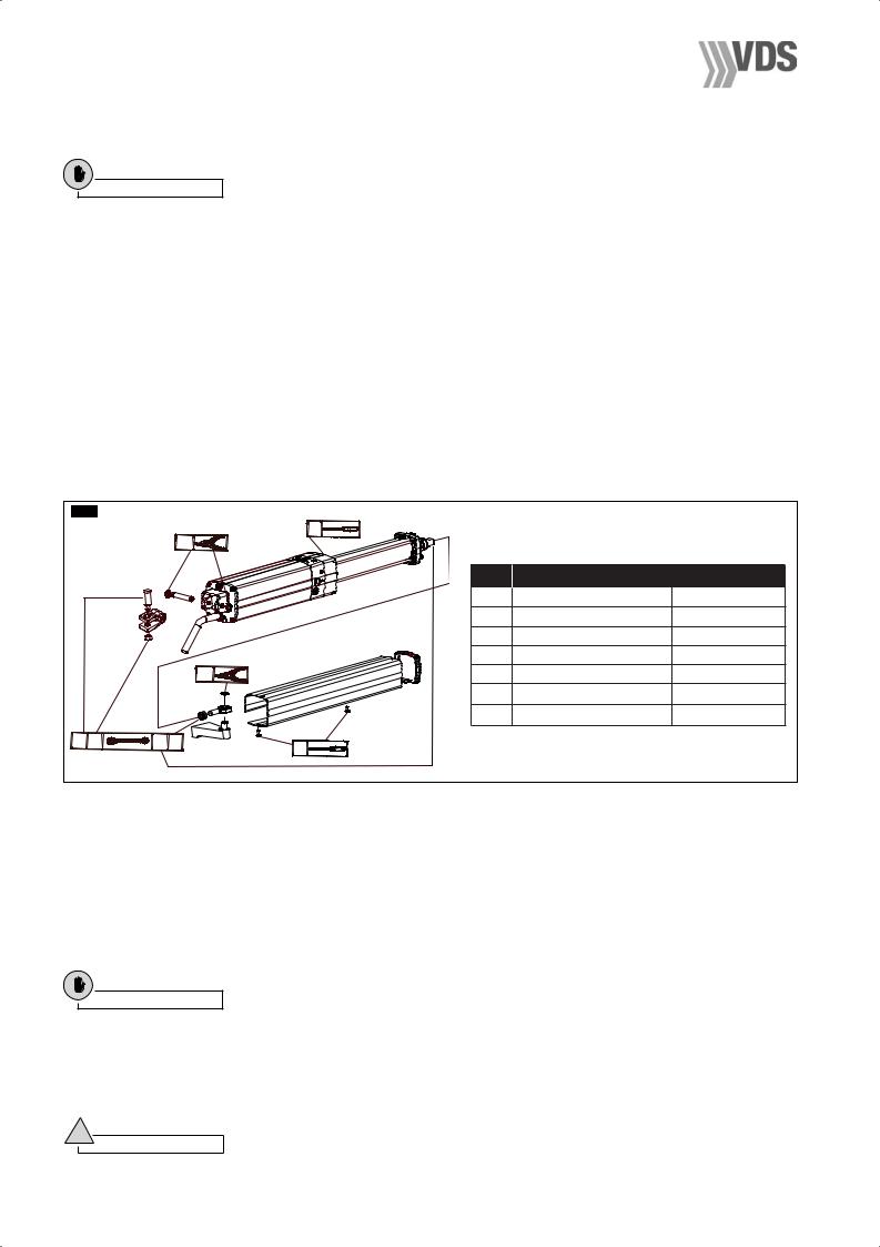
3.1CHECKING THE OPERATOR COMPONENTS
Check that the model code displayed on the operator packaging corresponds to the code on the identification plate on the operator itself (B3).
Also,before starting with the mounting procedure, check that the packaging contains all the components listed below (B4) and that none of them is damaged.
1- Operator
2- Rod protection casing
3- Rod proctection casing cover
4- Rear mounting
5- Bushes
6- Fork
7- Rear pin
8- Locknut
9- Fork pin 10- Snap ring
11- Front mounting 12- Ball joint with nut 13- Snap ring
14- Capacitor
15- Self-threading screw
16- Release key
17- Plate for rear mounting
A- Complete front mounting assembly
B- Complete rear mounting assembly
B1B |
|
|
|
|
|
|
|
|
|
|
|
|
|
PLUMMET |
|
B3 |
|
|
|
|
|
|
|
|
|
|
eee |
eee |
|
|
|
|
|
|
eee |
|
|
|
|
|
|
|
eee |
|
|
|
|
|
|
|
x eee |
|
|
|
|
|
|
|
............ |
|
|
|
|
B4 |
|
|
|
|
|
|
|
|
|
|
|
|
|
|
16 |
|
|
4 |
7 10 |
9 |
1 |
||
|
|
|
|
|
|
|
|
B |
17 |
|
|
|
|
|
|
|
|
|
|
|
|
|
|
|
|
|
|
|
|
10 |
|
|
|
|
|
|
|
|
3 |
|
5 6 |
8 |
|
|
|
2 |
15 |
|
|
|
|
|
|
15 |
|
|
|
|
11 |
1213 |
|
||
|
|
|
|
|
|
||
|
|
|
|
|
A |
|
14 |
- 17 -
English
English
Installation
3.2 MOUNTING TOOLS
To mount the operator, a number of preparatory on-site jobs need to be done on the structure that is to be moved; for this, it is better to be equipped with the correct tools, so that the installer is able to work independently.
Caution |
The list of required tools is shown in the illustration and table (B5). |
|
Electric disk grinder - 230 V |
|
Dynamometer |
|
||
Protective goggles |
|
Plumb line |
|
|
|
Electric welder - min. power 230 V/100 amp. |
Spirit level (3-D) |
|
|||
Protective mask |
|
Graphitized |
grease |
|
|
Electrodes - min. ø 2 |
|
Oil - AprimOil HC 13 (specially formulated) |
|||
Soldering iron |
|
|
Zinc-spray cylinder |
|
|
Suitably powered electric drill - 230 V |
Anti-rust paint |
|
|||
Drill bits |
|
|
Paintbrushes |
|
|
Hollow cutter ø 67 for photocells and control panel |
Thinner for cleaning paintbrushes |
|
|||
mounting holes |
|
Wire brush |
|
|
|
Extension cable for welder |
|
Files |
|
|
|
Electric cable, cross-section 1.5 mm2, various colours + |
Hacksaws |
|
|
||
various types of terminals |
|
Scribers |
|
|
|
Electrical scissors |
|
Hammer |
|
|
|
Pliers for cable terminals |
|
Chisel for steel and masonry |
|
||
Tester |
|
|
Detergent wipes |
|
|
1/20 gauge |
|
|
Paper hand-towels |
|
|
Rule |
|
|
First aid kit |
|
|
Goniometer |
|
|
|
|
|
B5 |
|
1 |
|
|
|
|
2 |
|
|
|
|
|
|
|
|
|
|
|
|
|
POS. |
TOOL |
|
|
|
|
1 |
Screwdriver |
USAG 326/5x150 |
|
|
|
2 |
Gripper for snap ring on shaft |
USAG 128 P/1025 |
|
|
|
3 |
Screwdriver TC |
USAG 326 TC/2 |
|
|
|
4 |
Combined wrench 12 |
USAG 285/12 |
|
2 |
|
5 |
Combined wrench 13 |
USAG 285/13 |
|
|
|
6 |
Combined wrench 14 |
USAG 285/14 |
|
|
|
7 |
Combined wrench 17 |
USAG 285/17 |
6 5 |
4 7 |
3 |
|
|
|
|
|
|
|
|
|
4.INSTALLING THE OPERATOR
4.0POSITIONING THE MOUNTINGS
The following table (C1) indicates the recommended data for defining the position of the operator mountings in relation to the centre of rotation of the gate leaf.
The distances A and B will give:
•The useful stroke length (C) of the piston
•The peripheral velocity of the gate leaf
•The angle of maximum opening of the gate leaf
•The holding capacity of the lock in relation to distance E (which must always be less than B when the operator is fitted with a hydraulic lock); the distance E is obtained, in practice, by measuring the distance between front mounting fulcrum and gate hinge axis (see fig. C1).
Caution
•The sum A+B corresponds to the useful stroke length of the piston (C) for a 90° opening of the gate leaf.
•The minimum value of distances A and B is 70 mm; the maximum one is indicated in column B of the table (see fig. C1).
•Distances A and B must be as equal as possible in order to have a uniform peripheral velocity.
•If the gate leaf shall be opened by more than 90°, first of all find the best A and B measurements for mounting, then reduce distance B to the desired opening angle, making sure, by checking the distance Y, that the corner of the post does not interfere with the operator action.
!Warning
•The greater the distance B in relation to E, the more efficient the holding capacity of the hydraulic lock (for all types of operator).
•If the gate leaf is closed with an electric lock, then E must always be less than or equal to B (never greater).
-18 -
|
|
|
|
|
|
|
Installation |
|
|
|
|
|
|
|
|
|
|
|
|
|
|
|
|
|
|
|
|
C1 |
|
|
|
|
|
|
|
1 |
|
|
|
|
|
|
||
VALUES IN MILLIMETRES |
|
|||||||
|
|
|
|
|||||
|
|
|
L |
A |
B |
C |
Y Max. |
|
|
|
|
1200 |
130 |
140 |
275 |
90 |
|
|
|
|
÷ |
|
||||
2 |
3000 |
|
|
|
|
|
||
1)Wing rotation axis
2)Operator centre of rotation
4.1PREPPING FOR THE REAR MOUNTING
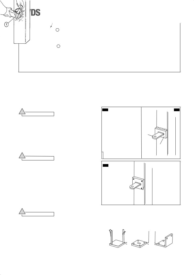
4.1.1 Operator fixed on iron posts
If the gate supporting posts are made of iron, it is necessary to fit a reinforcing plate for welding the rear operator mounting.
Perfectly clean the welding zone for the rear mounting with the special tool (C2 pos.1); make sure to remove any traces of paint or zinc coating.
Position the reinforcing plate (C3 pos. 2) in the rear mounting welding zone and weld it on the column, covering it from edge to edge.
The size of the reinforcing plate must be in proportion to the size of the column.
!Warning
•If the size of the column allows for it, use the standard plate provided.
4.1.2 Operator fixed on wooden posts
If the gate supporting posts are made of wood, it is necessary to fit a reinforcing plate on the column, covering it from edge to edge, in the rear mounting welding zone. The plate shall be fixed firmly on the column by means of fixing screws (C4).
The size of the reinforcing plate must be in proportion to the size of the column.
!Warning
•If the size of the column allows for it, use the standard plate provided.
4.1.3 Operator fixed on masonry posts
If the supporting posts for the gate leaves are made of masonry, fix the special metal plate complete with anchor bolts used to weld on the rear mounting of the operator to each of them.
Preparing the insets
If mounting insets have to be made in the posts for the rear operator mounting with metal plates, the measurements shown in fig.C6 must be adhered to.
C2 |
C3 |
3
2
C4
! |
|
|
|
|
|
|
|
|
|
Warning |
|
C5 |
A |
|
B |
|
C |
||
|
|
|
|
||||||
|
|
|
|
|
|||||
Remember that the inset is necessary when the distance |
|
|
(optional) |
|
(standard) |
|
* |
||
between the edge of the post and the centre of rotation of |
|
|
|
|
|
|
|
|
|
the gate leaf is greater than the distance Y (C1), or when |
|
|
|
|
|
|
|
|
|
the gate leaf is anchored to a continuous wall. |
|
|
|
|
|
|
|
|
|
Fixing the anchoring plates |
|
|
|
|
min 5 mm |
|
min 5 mm |
min 5 mm |
|
Fig. C5 shows some fixing examples by means of |
|
|
|
|
|
||||
different types of plates: |
|
|
|
|
|
|
|
|
|
|
|
|
|
|
|
|
|||
A - Plate with hooked fitting |
|
|
|
|
|
|
|
|
|
|
|
|
|
|
|
|
|||
|
|
|
|
|
|
|
|||
B - Plate with stud bolts, either glued or pressure- |
|
|
|
|
|
|
|
* CUT TO MEASURE |
|
|
fitted |
|
|
|
|
|
|
|
|
C - L-plate with stud bolts, either glued or pressure- |
|
|
|
|
|
|
|
(not supplied) |
|
|
|
|
|
|
|
|
|
||
|
fitted |
|
|
|
|
|
|
|
|
- 19 -
English

English
Installation
Caution
•The size of the plates must be proportioned to the size of the columns.
•If the A-type plate is used and has to be positioned in line with the operator axis, the hook fittings must be modified as shown in fig. C7.
Clean out any traces of cement or sand.
Drill four holes (C8 pos. 1), after marking the position of the holes, using the anchorage plate itself as a drilling guide mask.
Attach the plate with “FISCHER” expansion anchors of minimum ø 15 with M8 steel or cast iron screws (C8 pos. 2) (if the material the column is made of is able to hold the screws), or, if not, attach with glue as follows:
-Insert the mesh sheaths (C8 pos. 3) into the holes and inject the quick-dry glue (C8 pos. 4); see attached instructions for application method and quantity.
If the B-type plate is used:
-Insert the stud bolts (C8 pos. 5) into the sheaths (if the B-type plate is used).
-Fit the anchoring plate (C8 pos. 7) to the stud bolts.
If, on the contrary, the C-type plate is used:
-Insert the stud bolts (C8 pos. 5) into one of the two sides of the inset.
-Fit the anchoring plate (C8 pos. 7) to the stud bolts.
-Insert the two remaining stud bolts (C8 pos. 8).
At this point, if plates B or C are used, screw in all the fittings, nuts and washers by hand, without tightening; after about half an hour tighten up the stud bolts with a setscrew
wrench.
When finished, cut off the protruding parts of the stud bolts using the correct tool.
4.1.4 Rear operator mounting - special cases
For outward-opening gate leaves, the rear mounting has to modified using an L-plate as shown in (C9).
C6
Y
max. from hinge axis to plate edge
C7
C8 RECOMMENDED GLUE FITTING (other glue fitting systems
are available on the market)
Type B plate
Type C plate
C9
C8 |
PRESSURE FITTING |
|
Type B plate
For dimensions A,B and C consult table C1
Type C plate
Inside entrance
- 20 -

4.2FIXING THE REAR OPERATOR MOUNTING
Position the rear mounting (B4 pos. 4) at the height previously measured and weld it on the anchorage plate with two weld points (C9).
Check the lengthwise and crosswise alignment of the mounting (C10) with a water level.
Complete the welding and clean away the residues with a wire brush.
!Warning
•Before welding, ensure that there are no bushes (B4 pos. 5) in the mounting, and that the fitting hole is properly protected from weld residues.
•When the welded zone has cooled down, apply a coat of anti-rust paint.
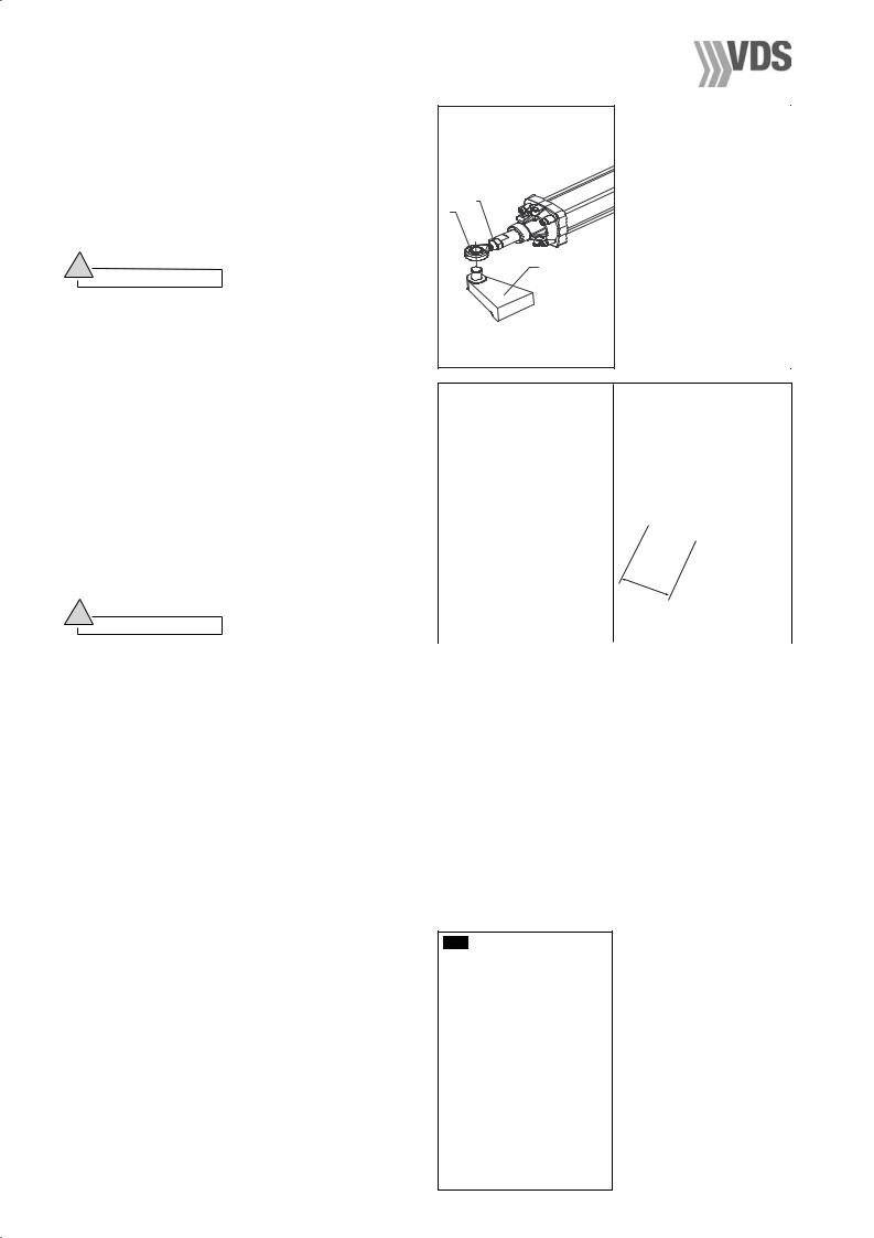
4.3TEMPORARY INSTALLATION OF THE OPERATOR
Temporarily mount the operator to find the correct fixing position of the front mounting.
!Warning
Handle the operator with care during assembly.
Fit the fork (C11 pos. 1) to the operator bottom. Lock the fork with the special pin (C11 pos. 2) and fix both with the two snap rings (C11 pos. 3).
Fit the two vibration damping bushes (C12 pos. 4) above and below the mounting.
Position the fork of the operator on to the mounting and lock it with the vertical pin (C13 pos. 5) after greasing abundantly.
!Warning
Grease both the pin and the housings abundantly.
Installation
|
|
|
|
C9 |
|
|
C10 |
|
|
|
|
C11
1
 2
2
3
3
|
|
|
|
|
C12 |
||||
|
|
C13 |
||
|
|
|
|
English
- 21 -
English
Installation
4.4 POSITIONING THE FRONT MOUNTING
Spread grease on the threaded stem of the ball joint (C14 pos.1), fit the ball joint, along with its nut (C14pos.2) and to the operator arm, screwing on to about halfway along the thread. Insert the pin (C14 pos. 4) into the ball joint, without fitting the snap ring.
Fit the fork (C14b pos.1) to the base of the operator with its pin (C14b pos.2) and fix in place with the two snap rings (C14b pos.3).
!Warning
•Check the strength of the mounting zone; if necessary, fit a strengthening plate of the correct size; the strengthening plate is especially important with gate leaves made from thin sheet steel.
•When cleaning the mounting zone for the operator front mounting, remove the operator and protect it from flying sparks.
Rest a water level (C16 pos.1) on the operator body (C16 pos.2) and level the operator.
Weld the front mounting of the rod to the gate leaf with two weld-points, protecting the rod from weld residues with a clean cloth (C17 pos.4).
Withdraw the jointed head of the operator from the front mounting; completely remove the operator itself from its temporary mountings, close off the flange with the correct plug; complete the welding, covering the pin - using a clean cloth or adhesive tape (C20 pos.5) - to protect it from weld residue, and then clean off the residue with a wire brush (C20 pos.6).
!Warning
•While welding the points on the front mounting with the electrode, always cover the rod with a clean cloth; a splinter of molten metal can cause irreparable damage to the machined surface and make the operator unusable.
•During welding, the operator must be disconnected from the electricity supply.
After cooling, apply a coat of rustproof paint to the welded zone (C19).
C14 |
|
C14b |
2
1
4
|
|
C16 |
C15 |
|
|
300 |
mm |
||
|
|
|
|
|
|
|
|
|
|
|
|
|
|
|
|
|
|
|
C17 |
|
|
C18 |
|
|
|
|
|
|
|
C19
- 22 -
4.5 FINAL INSTALLATION OF THE OPERATOR
4.5.1 Mechanical fixing
Fix both ends of the operator to the respective mountings.
Front fixing
Spread graphitized-type grease on to the frontal anchorage pin of the ball joint (C20 pos.1).
Spread graphitized-type grease on to the ball joint (C20 pos.2).
Fit the jointed head to the pin (C21pos.1) and fix in place with the snap ring (C21 pos.2).
Rear fixing
Fit the operator to the rear mounting with the fork pin (C22 pos.3) and its locknut (C22 pos.4).
With the gate leaf fully closed, re-check that the rod comes out from the operator of the defined measure; then tighten up the ball joint fitting to the rod using a CH 12 hexagonal wrench (C23 pos.5) and a CH 17 hexagonal wrench (C23 pos.6).
4.5.2 Checking the motion
!Warning
•When the mounting is completed, neutralize the hydraulic lock (if present in the operators) by turning the correct key through 180° counterclockwise, and move the gate-leaves manually to check on the smoothness of the movement; this should be done very slowly, otherwise the operators will take in air and, consequently, will have to be bled.
•Open and close the gate leaf to check that the operator can move freely without rubbing and without going against either the gate leaf or the gate post.
•After making the checks, reset the hydraulic lock by turning the release key fully in a clockwise direction.
4.5.3 Electrical connection
Make the electrical connection according to the wiring diagram (D1) - see paragraph “System electrical connection”.
Connect the supplied capacitor (B4 pos. 12) to the electric control unit according to the wiring diagram of the unit itself.
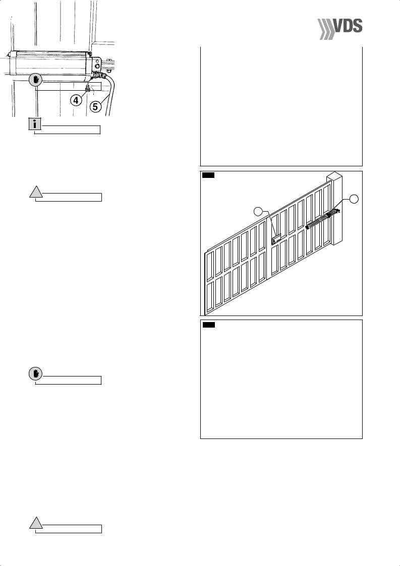
4.5.4 Fitting the protection casing and removing the bleed screw
Fit the protective casing (E1 pos. 1) to rod and insert into the operator.
Hold the casing bottom (E2 pos. 2) in position with a cross-head screwdriver (E2 pos. 3).
Fit the push-on cover (E3 pos. 2) on to the protective casing (E3 pos.1).
Tighten the fixing screw of the protective casing (E4 pos.1).
On completion of the assembly, remove the bleed screw
|
Installation |
C20 |
C21 |
|
English |
|
2 |
C22 |
C23 |
|
|
|
|
E1 |
|
E2 |
|
|
|
|
|
E3 |
E4 |
1 |
|
2 |
1 |
|
- 23 -
English
Final operations
(E5 pos. 4) using a CH7 hexagonal wrench. |
|
|
|
|
E5 |
Fit the protective sheath to the power supply cable (E5 pos. 5) if necessary.
Caution
One drop of hydraulic oil coming out of the duct created by the screw elimination (E5 pos. 4) is
normal.
Information
After installation, an appropriate warning sign must be attached to the gate (E6 pos. 2.)
When completely assembled, the operator should appear as shown in the figure (E6 pos. 1).
4.5.5 |
Bleeding |
E6 |
|
|
|
|
|
||
! |
Warning |
|
|
1 |
|
|
|
||
Before proceeding in setting the operator, bleed it. |
2 |
|
|
|
Start the operator after having checked the setting of the |
|
|
||
|
|
|
||
pressure relief valves and move it to stroke end either in |
|
|
|
|
open or close position. Rotate on the key (see paragraph |
|
|
|
|
6) and lock and unlock the operator a dozens of times. |
|
imat |
ic |
|
|
|
Apr |
|
|
5. |
CHECKS AND ADJUSTMENTS |
|
|
|
5.0 CHECKING AND ADJUSTING THE THRUST |
|
|
|
|
|
FORCE |
|
|
|
With the gate leaf moving, measure the thrust force |
|
|
|
|
at the end of the gate leaf, using a dynamometer (E7 |
|
|
|
|
pos. 1). |
|
|
|
|
The thrust force must never exceed 15 Kg (147 N). |
|
|
|
|
If necessary, adjust the working pressure of the |
E7 |
|
|
|
operator. |
|
|
||
Using a broad, flat-headed screwdriver, turn the control |
|
|
|
|
valves clockwise to increase the pressure and counter- |
|
|
|
|
clockwise to reduce it. |
|
|
|
|
Adjust both opening (silver - E8 pos. 2) and closing |
|
|
|
|
pressure (gold - E8 pos. 1). |
|
|
|
|
Caution
•The opening thrust of the gate leaf should be set slightly higher than the closing thrust.
•After making the settings, make another check with the dynamometer to see if the thrust force corresponds to the setting; if it doesn’t, then the setting needs to adjusted again.
•If the gate leaf requires an excessively high pressure to move it, then make another thorough check of the mechanical parts, the plumb and the free movement of the gate leaf itself.
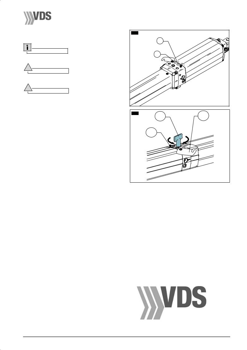
6.0EMERGENCY MANOEUVRE - USE OF THE MANUAL RELEASE
In the event of a power failure, release the operator in order to open the gate by hand.
To gain access to the release valve, it is enough to loosen the screw (E9 pos. 2) and open the small cover (E9 pos. 3) by rotating it.
Unlock the operator by turning the triangular key provided (E9 pos. 1) counter-clockwise. After the operation, re-lock the operator by turning the key clockwise.
!Warning
After locking and releasing operations, remember to re-close the cover.
- 24 -
Notes for the user
7.NOTES FOR THE INSTALLER
7.0Maintenance
Information
Periodically check the proper functioning of the operator. Do this check at least every 12 months
!Warning
Maintenance must be performed only by skilled technicians.
!Warning
Before doing any maintenance job, turn the operator off by means of the differential switch of the electric system.
•Grease the joints with graphitized grease every year.
•Check the general condition of the gate structure.
•Check the mechanical resistance of hinges, operator mountings and stops.
•Ensure the installed safety devices are in working order (photocells, rubber barriers,…) and adjust the thrust force at the end of the gate leaf (max. 147 N).
•Ensure the electrical system and the differential switch are efficient.
•Check the setting of the pressure relief valve.
•Check the tightening of the safety lock.
•Depending on the use of the operator, check the oil level of the system.
7.1Troubleshooting
E8 |
|
|
|
1 |
|
|
2 |
|
|
|
English |
E9 |
1 |
3 |
|
||
|
2 |
|
|
Fault type |
Probable cause |
Solution |
|
|
|
By operating the opening control, the |
No power supply. |
Turn the power on. |
|
|
|
|
|
|
||
|
Defective fuse. |
Replace the defective fuses with new ones having |
|
||
|
leaf does not move and the electric |
|
|||
|
the same amperage. |
|
|||
|
motor of the operator does not run. |
|
|
||
|
The power cable of the operator is damaged. |
Replace the power cable and find and rectify |
|
||
|
|
|
|
||
|
|
|
the fault. |
|
|
|
|
|
|
|
|
|
|
|
If the operator has a hydraulic release, |
Turn the valve fully in a clockwise direction (E9 pos.1). |
|
|
|
|
check that the release valve setting is |
|
|
|
By operating the opening control, the |
|
closed. |
|
|
|
|
If the operator doesn't have a hydraulic |
Screw the pressure setting valve clockwise |
|
|
|
electric motor of the operator runs but |
release, adjiust the opening pressure setting. |
(par.5 - E8 pos.2) |
|
|
|
the leaf does not move. |
If the operator has been exposed to the sun for |
Check the operator mounting, as described in |
|
|
|
|
|
a long period, with the gate closed, check that |
|
|
|
|
|
this manual. |
|
|
|
|
|
the operator piston is not in the fully advanced |
|
|
|
|
|
Check the measure of the piston stroke. |
|
|
|
|
|
position, i.e. with the rod completely out. |
|
|
|
|
|
|
|
|
|
|
|
Probably air in the cylinder. |
Detach the operator from its front mounting |
|
|
|
|
and make a few opening and closing movements; |
|
|
|
|
|
|
then re-fit to the front mounting. |
|
|
During the motion, the operator jerks. |
Oil in the cylinder not enough. |
Check for oil leaks; if any, address to a Repair Centre. |
|
|
|
|
|
|
||
|
|
|
|
|
|
|
|
|
The front and rear operator mountings |
Repair or strengthen the mountings. |
|
|
|
|
move or have been fitted incorrectly. |
|
|
|
|
|
|
|
|
|
|
|
|
|
|
|
SPACE RESERVED FOR INSTALLER |
|
|
|
|
|
PLEASE GIVE A COPY OF THIS PAGE TO THE USER |
|
|
||
Via Circolare, sn
65010 Santa Teresa di Spoltore - Pescara
Tel. 085/4971946 - Fax 085/4973849
- 25 -

Français
Index / Caractéristiques |
|
|
1 Caractéristiques de l’automatisme |
|
|
1.0 |
Caractéristiques générales............................................................................................................................. |
27 |
1.1 |
Données techniques....................................................................................................................................... |
27 |
1.2 |
Vérification de l’automatisme choisi .............................................................................................................. |
27 |
2 Description du système d’automatisation |
|
|
2.0 |
Disposition des composants........................................................................................................................... |
28 |
2.1 |
Branchement electrique du système ............................................................................................................. |
28 |
3 |
Contrôles et opérations précédant l’installation de l’automatisme |
|
3.0 |
Contrôles sur le portail ................................................................................................................................... |
29 |
3.1 |
Vérification des composants de l’automatisme .............................................................................................. |
29 |
3.2 |
Outils nécessaires pour le montage............................................................................................................... |
30 |
4 Installation de l’automatisme |
|
|
4.0 |
Mise en place des connexions ....................................................................................................................... |
30 |
4.1 |
Préparation pour la fixation arrière ................................................................................................................ |
31 |
4.1.1 |
Automatisme fixé sur des piliers en fer ............................................................................................................................. |
31 |
4.1.2 |
Automatisme fixé sur des piliers en bois........................................................................................................................... |
31 |
4.1.3 |
Automatisme fixé sur des piliers en maçonnerie............................................................................................................... |
31 |
4.1.4 |
Cas particuliers de fixation arrière de l’automatisme......................................................................................................... |
32 |
4.2 |
Fixation de la patte arrière de l’automatisme ................................................................................................. |
33 |
4.3 |
Installation provisoire de l’automatisme ......................................................................................................... |
33 |
4.4 |
Mise en place de la patte de fixation avant .................................................................................................... |
34 |
4.5 |
Installation finale de l’automatisme ............................................................................................................... |
35 |
4.5.1 |
Fixation mécanique ........................................................................................................................................................... |
35 |
4.5.2 |
Contrôle du mouvement.................................................................................................................................................... |
35 |
4.5.3 |
Branchement électrique .................................................................................................................................................... |
35 |
4.5.4 |
Montage du carter de protection et démontage de la vis de purge................................................................................... |
35 |
4.5.5 |
Purge de l’air ..................................................................................................................................................................... |
36 |
5 |
Contrôles et réglages |
|
5.0 |
Contrôle et réglage de la force de poussée ................................................................................................... |
36 |
6 |
Manœuvre d’urgence |
|
6.0 |
Manœuvre d’urgence - utilisation du déblocage manuel .............................................................................. |
36 |
7 |
Notes pour l’installateur |
|
7.0 |
Entretien......................................................................................................................................................... |
37 |
7.1 |
Recherche des pannes .................................................................................................................................. |
37 |
- 26 -

Caractéristiques / Opérations préliminaires
1.CARACTERISTIQUES DE L’AUTOMATISME
1.0CARACTERISTIQUES GENERALES
•Automatisme oléo-hydraulique pour portails à battant conçu pour des zones résidentielles.
•L’automatisme, si installé correctement, est conforme aux normes de sécurité actuellement en vigueur.
Liste des versions:
PH1: Blocage hydraulique seulement en fermeture (avec automatisme inaccessible lorsque le vantail est ouvert) PH: Sans blocage hydraulique - freiné (vantail actionnée lentement à la main, avec une petite résistance; il est
doté d’un dispositif de déblocage pour faciliter l’ouverture - électro-serrure nécessaire).
•La version avec blocage hydraulique en fermeture évite l’installation de l’électro-serrure, car il assure la fermeture des vantaux jusqu’à 1,8 mètres de long.
•Le déblocage d’urgence (à utiliser en cas de panne de courant) permet une commande manuelle aisée du portail par la clé triangulaire très simple à utiliser. Le dispositif de déblocage est facilement accessible à travers un petit couvercle placé sur le coffret supérieur de l’automatisme.
•La protection anti-écrasement est assurée par des clapets très sensibles, réglables en phase d’installation.
A |
|
|
90 |
|
|
Français |
B |
C |
|
|
|
||
|
|
A (mm) |
1060 |
|||
|
|
|
|
|||
|
|
70 |
97,5 |
B (mm) |
698 |
|
|
|
C (mm) |
274 |
|||
|
|
|
|
|
||
1.1 DONNEES TECHNIQUES |
|
|
|
|
|
|
CARACTÉRISTIQUES |
PH1 |
PH |
|
|
|
|
Tension d'alimentation monophasée |
230 V±10% 50 Hz |
|
|
|
|
|
Puissance |
250W |
|
|
|
|
|
Pression moyenne de service |
30 bar |
|
|
|
|
|
Force de poussée à 10 bar |
962 N |
|
|
|
|
|
Force de traction à 15 bar |
1140 N |
|
|
|
|
|
Temps d'entrée tige (course maximale) |
22 sec ±2 |
|
|
|
|
|
Temps de sortie tige |
22 sec ±2 |
|
|
|
|
|
Longueur max. vantail |
1,8 m |
3 m |
|
|
|
|
Longueur min. vantail |
1,2 m |
|
|
|
|
|
Température de fonctionnement |
-20° / + 70°C |
|
|
|
|
|
Ecartement maximal des trous de fixation |
1002 mm ± 5 |
|
|
|
|
|
avec tige sortie |
|
|
|
|
|
|
Course maximale tige standard |
270 mm |
|
|
|
|
|
Poids avec huile |
8 Kg |
|
|
|
|
|
Quantité huile |
0,6 lt. |
|
|
|
|
|
Huile type |
AprimOil HC13 |
|
|
|
|
|
Degré de protection |
IP 55 |
|
|
|
|
|
!
Attention
Le niveau de bruit des modèles décrits auparavant rentre dans les limites maximales établies par les normes CEE pour le fonctionnement d’automatismes non fixés à portails ou piliers.
1.2VERIFICATION DE L’AUTOMATISME CHOISI
Avant de procéder au montage, il faut vérifier le type d’automatisme choisi par rapport aux caractéristiques et aux dimensions de l’élément à actionner.
Prudence
•Le choix d’un automatisme correct assure un fonctionnement correct du groupe et réduit la possibilité de pannes.
!
Attention
•Les versions décrites auparavant peuvent être utilisées même en cas de vantaux pleins (avec l’automatisme inaccessible lorsque le vantail est ouvert).
•Le modèle PH1 est adapté pour une utilisation dans des zones venteuses et ne doit pas être installé sur des vantaux supérieurs à 1,8 m de long.
!
Attention
La vitesse périphérique du vantail doit toujours être conforme aux limites des normes de sécurité en vigueur. Ne pas installer d’automatismes rapides sur des vantaux larges afin d’éviter des chocs violents contre les arrêts du portail (voir tableau “Données techniques” ).
- 27 -

Français
Opérations préliminaires
2.DESCRIPTION DU SYSTEME D’AUTOMATISATION
2.0DISPOSITION DES COMPOSANTS
A- Clignotant (à placer dans un point bien visible des deux côtés de passage)
B- Photocellule de sécurité
C- Dispositif de commande manuelle à clé (magnétique, numérique, par clavier, mécanique, etc.)
D- Dispositif de contrôle à microprocesseur placé dans une boîte étanche (à placer, si possible, à l’abri des intempéries)
F- Boîte de dérivation étanche pour l’alimentation de l’automatisme (conseillée) à placer de façon à ce que les câbles ne soient pas sujets à des efforts dangereux lors du mouvement
G - Antenne
H- Automatismes série PH
I- Electro-serrure (optionnelle)
L- Arrêt mécanique pendant l’ouverture
M- Arrêt mécanique pendant la fermeture
N- Mise à la terre des structures métalliques
Informations
Pour d’autres dispositifs de sécurité (optionnels), voir le tarif.
2.1BRANCHEMENT ELECTRIQUE DU SYSTEME
-Pour effectuer les branchements électriques, respecter rigoureusement les instructions fournies avec les composants en suivant le schéma indiqué en D1.
!
Attention
•Effecteur le branchement électrique de chaque composant après l’installation.
•L’installation doit être conforme aux normes de sécurité en vigueur.
•Pour la connexion, utiliser des câbles électriques avec une section de 1,5 mm2.
•S’il s’avère nécessaire de protéger le câble d’alimentation de l’automatisme avec une gaine de protection, effectuer l’opération avant de raccorder le câble aux boîtes de dérivation.
!
Attention
•Chaque automatisme est fourni complet avec condensateur de courant. Lors de l’installation, relier le condensateur à l’intérieur de l’équipement électrique en suivant le schéma fourni.
-Une fois les branchements électriques effectués, vérifier la force de poussée à l’extrémité du vantail et, si nécessaire, régler les pressions comme indiqué dans le paragraphe spécifique.
D1 1
2 |
5 |
|
|
|
|
|
6 |
1 |
Antenne |
|
|
|
||
3 |
9 |
|
2 |
Clignotant |
9 |
4 |
3 |
Photocellule récepteur |
|
|
|
|
4 |
Photocellule émetteur |
|
|
|
5 |
Tableau à boutons-poussoirs intérieur |
7 |
|
|
6 |
Bouton-poussoir à clé |
|
|
7 |
Electro-serrure |
|
8 |
|
|
||
|
|
|
8 |
Appareil électronique |
|
|
|
9 |
Boîte de dérivation |
6A
0,030 A
- 28 -
 Loading...