

Page 1
INSTRUCTION MANUAL
HYDRAULIC GAT E
PHV 240-PHV 360
Ed1. 14/12/09 (Italiano)
Page 2
Declaration of Conformity
Company Name: VDS, Internacional Co. Soc. Coop..
Address: Via Circolare P.I.P. Sn – 65010 Santa Teresa di Spoltore (PE)
National Identity Number (CIF/NIF): it 01807970684
C E R T I F I ES:
That the hydraulic equipment PHV240-PHV360 conforms to the following EU Directives:
89/392/EEC On the approximation of the laws of the Member States relating to machinery.
91/368/EEC Council Directive amending the previous Directive on the approximation of the laws of the Member States to
93/44/EEC Council Directive amending Directive 89/392/EEC on the approximation of the laws of the Member States to
93/68/EEC Regulating the Directive on simple pressurised containers, construction products, electromagnetic
2004/108/EEC Council Directive amending Directive 89/336/EEC on approximation of the laws of the Member States to
73/23/EEC On the approximation of the laws of the Member State son electrical material destined for use with specific
EU-EN 292-2/A1 Safety of machinery. Basic Concepts and general principles of design.
EU-EN 60204-1 Safety of machinery and electrical equipment of machinery.
EU-EN 292/1 Safety of machinery. Basic concepts and general principles of design.
EU-EN 418 Safety of machinery and emergency Shopping equipment, functional aspects.
EU-EN 982:96 Safety of machinery. Safety requirements for systems and components of hydraulic and pneumatic
This equipment bears the stamp of EEC conformity
Santa Teresa di Spoltore il 26 maggio del 2009
Company representative
GIUSEPPE DIODATO
machinery.
machinery.
compatibility, machinery, individual protection equipment, non automatic weighing machinery, terminal
telecommunication equipment and electrical material destined for use with specific voltage limits.
electromagnetic compatibility.
voltage limits.
transmissions Hydraulic.
Page 3

IMPORTANT SAFETY INSTRUCTIONS
the following instructions.
.
inappropriate
the
environment. The presence of inflammable gases or smoke
it is also necessary to install
that will prevent any
es it is also necessary to install at least one light signal as well as a
The installation of this equipment, the electrical connections and maintenance of the equipment may only be
cause severe injury and/or death, for which
rential and a thermal
safety
es are properly working and that the pressure force is adjusted to the minimum according to regulations
and properly balanced. The
the equipment, contact a qualified technician. DO NOT try to repair the equipment
remote
you must learn how to use the manual release mechanism according to the
instructions in a safe place. Make sure that all persons who use the gates or who may be near
a copy of these safety
WARNING!
Incorrect installation or inappropriate use may cause serious personal injury.
This installation manual and safety instructions are an integral part of the product and must be supplied to the user
These instructions should be retained by the owner and/or operator of the gate.
This product has been designed and constructed exclusively for the use indicated in this manual. Any
use of this product may result in damage to the product and/or personal injury.
To ensure proper functioning of the product and personal safety only use the mounting equipment supplied and
spare parts and accessories supplied by the manufacturer.
Do not install this equipment in an easily flammable
are a serious threat to personal safety.
This equipment has an anti crushing safety device. In addition to this safety device
additional safety devices (for example: photo cells and/or pressure sensitive strips, etc.)
danger resulting from mechanical movement (for example crushing, pulling or ripping).
In addition to the above mentioned safety devic
printed notice fixed to the gate.
To reduce the risk of injury or death
it is important to closely follow all of
carried out by qualified technicians.
the manufacturer will not be held responsible.
For protection against electrical overload or short circuit, always install a 0.03 amp diffe
magnetic switch with a contact aperture of at least 3mm
This equipment must be earthed with a yellow/ green cable, connected to the earth terminal in the junction box.
The safety of this product is only guaranteed if the equipment is properly earthed.
Before operating this product you must ensure that all connections have been properly made, that the
devic
regarding automatic doors (EU Directive 89/392 and EN 12453 y EN 12445 norms).
Before installing this equipment, ensure that the structure of the gate is strong enough
gates
must work freely in both directions and have no friction points before the automatic operator is installed.
Failure to meet this requirement may
SAFETY INSTRUCTIONS FOR THE USER
In the event that a malfunction in
yourself.
Do not allow children or pets near the gate. Never allow children to play with the gate controls. Keep the
control in a safe place, out of reach of children and unauthorised persons.
In the event of a power cut or emergency,
procedures found in this installation manual
Keep these safety
the gates when they operate are aware of the dangers associated with automatic opening gates
If you sell or rent the property with this equipment installed, give the new owner or tenant
instructions
Ed1. 14/12/09 (English) 2 of 10
Page 4
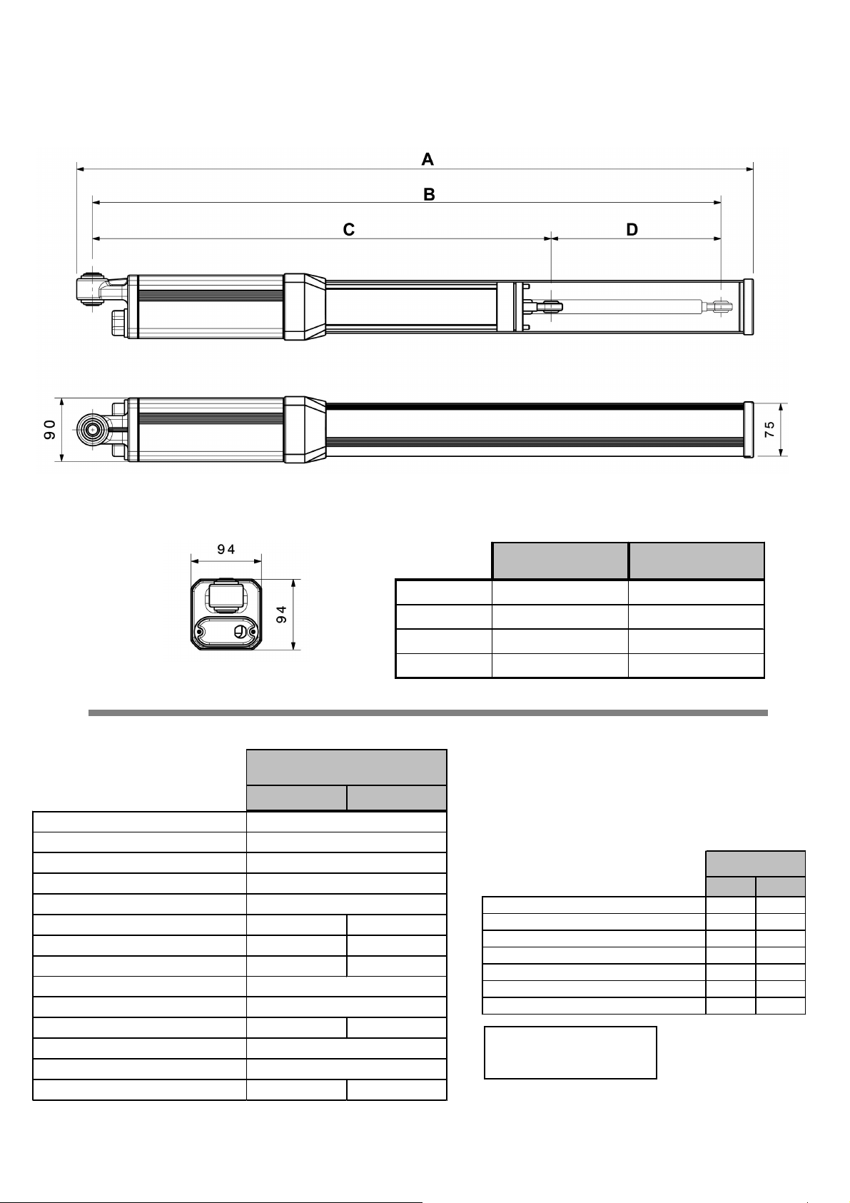
TECHNICAL DATA MODEL: PHV
●
●
●
●
●
●
●
●
●
●
PHV
TECHNICAL DATA
Current
Power
Consumption
Condenser
Maximum Pressure
Hydraulic Arm
Hydraulic arm exit time
Hydraulic arm entry time
Compression
Traction
Max. Length of gate leaf
Temperature Range
Thermic Protection
Weight
Dimensions
PHV
240 360
230V 50HZ
276 W
1,3 A
16 uf
50 bar
242 mm 362 mm
28 sec. 40 sec.
23 sec. 34 sec.
0 to 7793 N (795Kg)
0 to 6252 N (638Kg)
4 m 6 m
-15 to 80°C
100°C
11 Kg 12 Kg
A
B
C
D
PHV240PHV360
985 mm 1225 mm
915 mm 1155 mm
673 mm 793 mm
242 mm 362mm
FEATURES
SB BAC
HYDRAULIC LOCK OUT PUT
BLOCK OPEN & CLOSE
BLOCK CLOSE
BLOCK OPEN
REVERSABLE IN BOTH DIRECTIONS
ANTI-WIND REGULATION
BUFFER STOP CLOSE
SB = WITHOUT BLOCK
BAC = BLOCK, OPEN, CLOSE
Ed1. 14/12/09 (English)3 of 10
Page 5

FREQUENCY OF USE
The curve below allows calculation of the maximum working time (T) depending on the frequency of use (F).
To ensure correct operation of the equipment the working time should be within the shaded area.
These trials have been carried out at a temperature of 22ºC. If the equipment is operating at a higher temperature or is
exposed to direct solar radiation, the frequency of use can be reduced by 20%.
%F : use factor
Ta : opening time
Tc : closing time
Tp : pausing time
Ti : time between complete operations
E.G. Model 360
E.G. Model 240
%F= _______________ x100
WORK AREA
(F) Use Factor
(opening-closing)
Ta+Tc
Ta+Tc+Tp+Ti
(T) Time (Hours)
Graph.1
Note. 5 seconds more are needed to assure the complete opening and closing of the door.
There are heavy use times during the day where vehicle transit is higher. Calculations should be carried out during this
period of time.
E.G.
What is the maximum working time for a door that has a pause of 30 seconds and a time between cycles of 40
seconds?
CALCULATION FOR
PHV240
CALCULATION FOR
PHV360
Ta+Tc
%F= x100
Ta+Tc+Tp+Ti
Ta+Tc
%F= x100
Ta+Tc+Tp+Ti
%F= x100
%F= x100
28+33
28+33+30+40
39+45
39+45+30+40
46,5%
54.5%
2h
CONCLUSION: Once obtained data has been applied to
graph1, the maximum time of use for model 240 is 2h:15min
and for 360 is 1h:30min.
1h
Considering the quotas, model 240 should be used.
TIME (HOURS)
0
PHV240
Graph.2
PHV360
Ed1. 14/12/09 (English)
4 of 10
Page 6

MOUNTING HEIGHTS
MAX.
HEIGHT
LIGHT
400KG
MED.
600KG
HEAVY
800KG
Fig..1
PHV 240
110°
PHV 240
110°
PHV 240
110°
Max. 4m
PHV 240-95°
PHV 360-115°
PHV 240-95°
PHV 360-115°
PHV 360
115°
Max. 6mMax. 2m
PHV 360
95°
PHV 360
90°
Fig..2 Fig..3
INWARD OPENING (Fig.2)
M A B C
85° 195 185 90
90° 180 180 90
95° 165 180 90
100° 150 180 90
105° 140 180 90
110° 125 180 90
115° 115 180 90
120º 105 180 90
OUTWARD OPENING (Fig.3)
PHV 360
M A B C
85° 200 180 100
90° 180 180 100
95° 165 180 100
100° 150 180 100
105° 125 180 100
Ed1. 14/12/09 (English)5 of 10
INWARD OPENING (Fig.2)
M A B C
85° 130 125 70
90° 120 120 70
95° 110 120 70
100° 100 120 70
105° 93 120 70
110° 85 120 70
115º 85 115 70
OUTWARD OPENING (Fig.3)
PHV 240
ALL MEASUREMENTS IN MM FROM CENTER OF
HINGE
M A B C
85° 130 120 80
90° 120 120 80
95° 110 120 80
100° 100 120 80
Page 7

SPECIAL MEASUREMENTS INWARD OPENING (Fig.2)
MOUNTING QUOTAS 240 (C=70)
EXAMPLE (STANDARD)
EXAMPLE (SPECIAL DIMENSIONS)
MOUNTING QUOTAS 360 (C=90)
*measurements in mm.
In some cases it may be necessary to vary the standard dimensions, e.g., because of space restrictions in fixing the supports. The above
graphs show dimension ranges for inward opening 360 and 240 models.
At the top part of each graph are the range of gate opening angles and a series of diagonal lines from which the values of A and B may
be determined (fig.2 page 5 ). These values should be as near as possible to those determined by the thick vertical line.
The dimension for C is constant at C = 90 mm for model 360 and C = 70 mm for model 240.
Example: What should be the value for A and what model should be used for a gate with an opening angle of 100º where B = 140?
Answer: Model 360 where A =195 mm. See the example in the above graph shown by the dotted line for the 360 model : EXAMPLE
(SPECIAL DIMENSIONS))
Conclusion: It would not be possible to use the 240 model because the value for A would be outside the minimum for this model.
Ed1. 14/12/09 (English) 6 of 10
Page 8

MOUNTING INSTRUCTIONS
Fig.3Fig.2Fig.1
Fig.6Fig.5Fig.4
Fig.9Fig.8Fig.7
Fig.12Fig.11Fig.10
Ed1. 14/12/09 (English)
7 of 10
Page 9

1. Fix the pillar support (Fig.1 Page 7) shortening or lengthening the support according to the
dimensions A and B shown in the table on page 4. The support should be fixed at a height where the gate
has a sufficiently rigid surface to fix the gate support , bearing in mind that the gate support will be fixed
15 mm lower than the pillar support. (Fig.1 Page 5).
2. Shorten or lengthen the gate support according to the dimensions for C shown in the table on page 5.
Connect the gate opener to the gate support, with the rod completely extended (Fig.2 Page 7) and with
the swivel joint nut fully tightened (Fig.3 Page 7). Once this has been done use a spirit level (Fig.4
Page 7) to mark the position of the gate support on the gate. Dismantle the gate support and fix it to the
gate using the markings previously made.
3. Mount the motor and unscrew the swivel joint nut three turns to ensure closure. Attach the security
ring and the safety bolt supplied.(Fig.6 Page 7).
EARTH
4.Electrical connections: Unscrew the end cover and connect
the terminals according to the following diagram:
COMMON
CONDENSER
5. Open the door manually to the desired open position, slide the collar stopper along the arm (Fig.9
Page 7) up to the front cover plate, fixing its position with the Allen key. The hydraulic transmission can
then be plugged in and started. Re-position the collar stopper to the desired position if the angle of
opening is not the desired one.
6. Once the motor is working correctly the limit valves can be adjusted (Fig.10 Page 7). The limit valves
control the force and are independent in opening (blue limit valve) and closing (red limit valve) the gate.
The screws can be adjusted by turning them a maximum of 45º,and should be adjusted slightly above the
minimum possible, in this way the force of the hydraulic system is reduced thus increasing safety.
7. The closing buffer can then be adjusted (Fig.11 Page 7), thus avoiding the door banging closed.
To adjust the closing buffer turn the screw a maximum of 10º( If the buffer valve is completely closed
then 15mm of buffering will be lost) .
8.The aluminium arm cover can then be pressured into position (Fig.12 Page 7), followed by its plastic
cover and the end cover.
OPERATION OF THE HYRAULIC LOCK
With hydraulic powered gates it is necessary to consider the type of opening required:
- Inward opening (Fig.2, Page 5)
Kit ‘KM’ should be connected to
position 2 (see diagram).
- Outward opening (Fig.3, Page 5)
Kit ‘KM’ should be connected to
position 1 (see diagram).
Ed1. 14/12/09 (English)
2 1
8 of 10
Page 10

BLOCKING FUNCTION
Red closed - Blue open
The BAC system used in the
PHV range provides a wide range offeatures which can be adjusted
to ensure that the equipment may be adjusted for different requirements.
EMERGENCY RELEASE SYSTEM
This valve allows us to override the system in order to
operate the gate manually in the event of power cuts. To move
the gate manually , open the cover and turn the valve 360º
anti clockwise . To return to the automatic system turn the
valve clockwise.
IMPORTANT: If the valve is not tight the motor will not
function.
BAC AND ANTI-WIND SYSTEMS
Under view of motor.
By adjusting the red and blue valves (located under the
motor), gate actions can be reversed.
The options are as follows:
ADJUSTMENT OF BAC VALVES
Red open - Blue closed
Opening blocked and closing reversed
Opening reversed and closing blocked
Red closed - Blue closed
Opening and closing blocked
RED
BLUE
Red open - Blue open
Opening and closing reversed.
IMPORTANT: if these valves are slightly opened they serve as an excellent anti-wind system. The
pressure of the gate can be adjusted with the motor not working.
A lock is required for gates over 1.8m in length.
Ed1. 14/12/09 (English)
Under view of the motor.
9 of 10
Page 11

BOX CONTENTS
*
*only BAC system
SPARE PARTS ACCESSORIES
Nº Description Ref. Nº Description Ref.
PHV240SBA112.21100.009Allen key no. 680738
PHV240BACA112.21200.0010Strengthening block70141
1
PHV360SBA112.22100.0011Set up bolts - bag95008
PHV360BACA112.22200.0012Wire housing95107
Plastic cover 70284 13 Stopper collar 95020
2
Plastic cover BAC 95011 14 OILMEDVA-JV oil (1 Litre)
3 Installation Instructions 50171 15 Hingee set with nut A232.11003.K1
Aluminium cover
4
Aluminium cover
5 End cover for aluminium arm cover 70046 Door support kit 360 A232.11002.K1
Support 240 95006 18 Hydraulic lock A232.21002.00
6
Support 360 95037 19 Hydraulic piping (m) 80736
7 Electric cable 4x0,75 L1,5m 70055 20 Hydraulic piping mounting kit A232.22003.K1
8 Door support 240 95007
Door support 360 95036
PHV2407004416Condenser 16 Uf80497
PHV36070197Door support kit 240A232.11001.K1
17
70466
Ed1. 14/12/09 (English)
10 of 10
 Loading...