

ELETTRONIC DIVISION
I
MANUALE D’ISTRUZIONE
E
ISTRUCCIONES DE USO
GB
INSTRUCTION MANUAL
Apparecchiatura di comando 2 Motori 24Vac
Cuadro electronico para dos motores 24Vac
Elettronic control panel for two 24Vac motors
EURO24M2
[
code
REV 15-11-12 SW-E-
E106]
|
ATTENZIONE!!
caso di non osservanza delle normative vigenti.
¡ATTENCIÓN!! Antes de efectuar la instalacion, lea attentamente el presente manual. La Empresa VDS no asumirà
responsabilidad alguna en caso de inobservancia de las normas vigentes en el pais donde se lleva a cabo la installacion
WARNING!! Before installing, thoroughly read this manual that is an integral part of this Kit. VDS declines any responsabilità in
the event curret stadards in the country of installation are not comlplied with.
Prima di effettuare l’installazione, leggere attentamente questo manuale. La VDS declina ogni responsabilità in
I
25-26
negativo
OFF
OFF
ON
ON
+
-
SEC TRASF
24V
230V
230V
AC
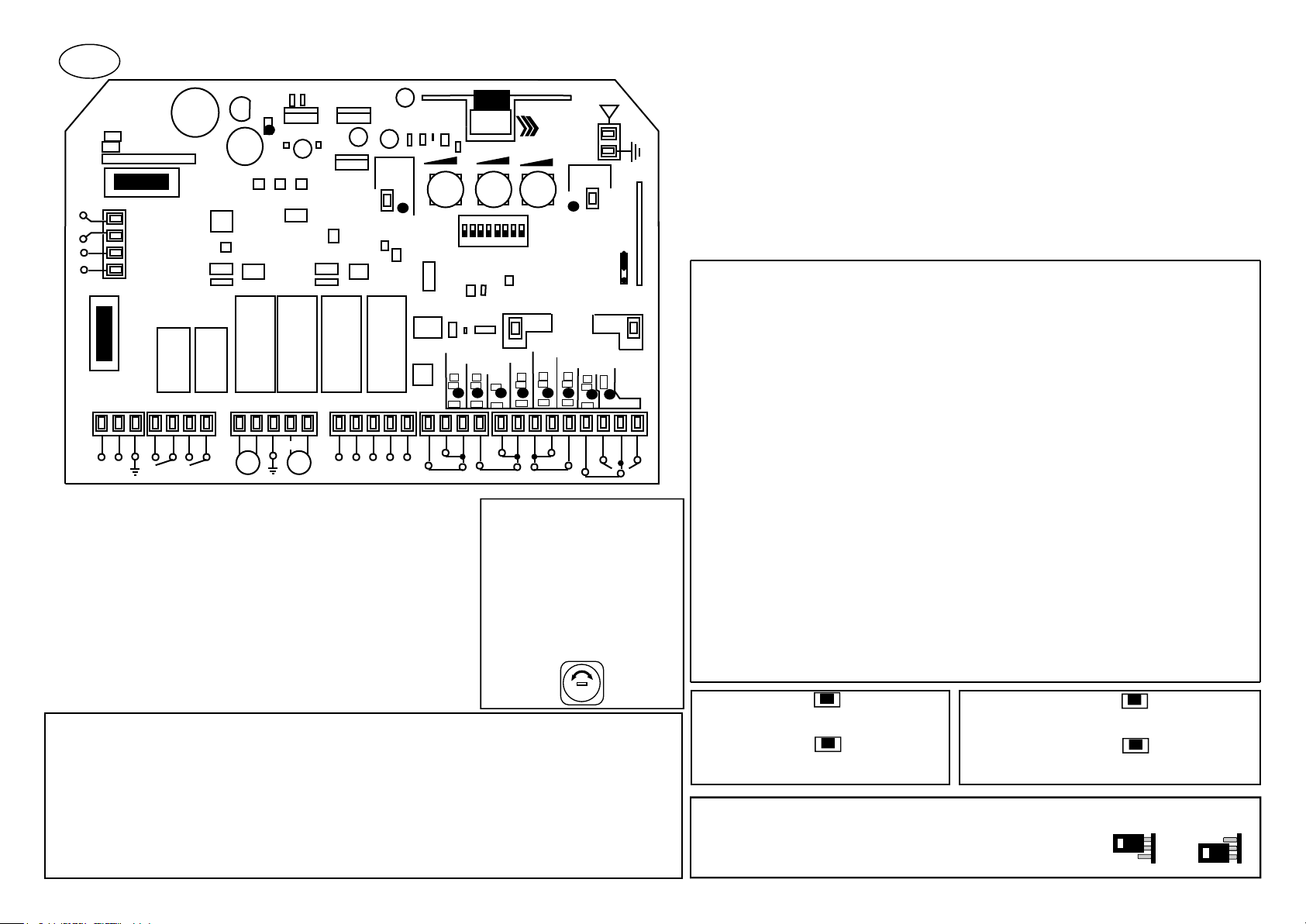
LETTURA DEI LED
L1 Led STATO
L2 Led RADIO
L3 Led PROG. TEMPI
L4 Led F.C. 2 CHIUSURA
L5 Led F.C. 2 APERTURA
L6 Led FOTO CHIUSURA
L7 Led F.C. 1 CHIUSURA
L8 Led F.C. 1 APERTURA
L7+L8 Led STOP
L9 Led PEDONALE
L10 Led START
LOGICA DI FUNZIONAMENTO DELLE SICUREZZE D.d.S. = dispositivo di sicurezza
IN. COSTA (15-17): Questo contatto protegge apertura e chiusura.
DIP 5 ON: L’impegno del D.d.S. provocherà l’arresto della manovra e l’inversione per 2 sec.
DIP 5 OFF: L’impegno del D.d.S. provocherà l’arresto dell’automazione.
In entrambi i casi al disimpegno dopo riprenderà la manovra di apertura
IN. PHOTO (16-17): Questo contatto protegge solo in chiusura.
In chiusura con l’impegno del D.d.S. si avrà l’inversione della marcia.
STOP (21-23): Il contatto se aperto provocherà l’arresto immediato dell’automazione in qualunque situazione
AMPEROSTOP: In apertura blocca e inverte la manovra per 2sec. In chiusura blocca e inverte la marcia.
EURO24M2
PROG
RADIO
L9
ANT
34 35
P1
J1
EXT
PG1
GATE1
M1
L10
STOP
PED
START
+
+
P2
+
PROG
TIME
L3
T1 T2 T3
ON
L2
1 2 3 4 5 6 7 8
DIP SWITCH
1-8
L4
L5 L6L7 L8
FCA2
FCC2
PHOTO
L1
+
FUSE
10A
30 31 32 33
FUSE
2A
1 2 3 4 5 6 7 8 9 31011 25 26 27 28 29 12 13 14 15 16 17 18 19 20 21 22 23 24
N.O.
M1 M2
FLASH
N.O.
LAMP
+
33V 0V 24V LOCK
PG2
GATE2
GATE2
M2
M2
VDS
FCC1
FCA1COSTA
TRIMMER T1
CRX
Acceso quando la centrale è alimentata
Acceso quando si accede in memoria radio
Acceso lampeggiante in programmazione
Acceso quando il finecorsa e in N.C.
Acceso quando il finecorsa e in N.C.
Acceso con il contatto di sicurezza chiuso
Acceso quando il finecorsa e in N.C.
Acceso quando il finecorsa e in N.C.
Entrambi accesi quando lo stop e in N.C.
A
cceso quando si da un impulso pedonale
Acceso quando si dà un impulso
Il Trimmer Power regola la coppia
e la sensibilità in manovra.
TRIMMER T2
Il Trimmer Power Slow regola la
coppia e la sensibilità in fase di
Rallentamento
TRIMMER T3
Trimmer Break regola il tempo di
pausa da 3 a 120 sec
CARATTERISTICHE TECNICHE
Alimentazione
Alimentazione motori
Uscita alimentazione accessori
Contatto lampeggiante, luce di cortesia
Tempo chiusura automatica
Tempo di manovra
Tempo luce di cortesia
Qtà di codici memorizzabili
Gestione trasmettitori
Frequenza
Temperatura di lavoro
Sensibilità
Omologazione
MORSETTI TIP DESCRIZIONE
1-2 230Vac Ingresso LINEA 230Vac
3 Terra
4-5 libera Ingresso LAMPEGGIANTE (contatto pulito Max 230V 10A)
6-7 libera Ingresso LUCE DI CORTESIA (contatto pulito Max 230V 10A)
8-9 24Vdc Ingresso MOTORE 1
10-11 24Vdc Ingresso MOTORE 2
12-14com N.C. Contatto FINECORSA CHIUSURA Mot.2
13-14com N.C. Contatto FINECORSA APERTURA Mot.2
15-17com N.C. Contatto COSTA/FOTOCELLULA.APERTURA
16-17com N.C. Contatto FOTOCELLULA CHIUSURA
19-18com N.C. Contatto FINECORSA CHIUSURA Mot.1
20-18com N.C. Contatto FINECORSA APERTURA Mot.1
21-23com N.C.
22-23com N.O. Contatto PEDONALE
24-23com N.O. Contatto di START (Impulso alternativo APRE/STOP/CHIUDE/STOP)
33Vdc
27-26
negativo
28-29 12Vdc Alimentazione elettroserratura
30-31 24Vac Ingresso SECONDARIO TRASFORMATORE 24Vac
32-33 230Vac Ingressi PRIMARIO TRASFORMATORE 230Vac
34-35 Ingresso ANTENNA (35 segnale, 34 calza / massa)
24Vdc Alimentazione accessori 24Vdc 250mA
Contatto STOP (Se non si usa inserire ponticello)
Alimentazione accessori 33Vdc 250mA o collegamento modulo
caricabatteria
PULSANTE P1
Tasto RADIO PROG per la memorizzazione
dei trasmettitori
PULSANTE P2
Tasto PROG TIME per la memorizzazione
della corsa
JUMPER J1 =
Possibilità di inserire una ricevente radio esterna tramite
connettore CRX, per aumento di codici memorizzabili
o cambio di frequenza. Inserire ponticello:
Selezione memoria radi o intern a o es ter na.
230V AC +/- 10%
24 Vdc
33V / 24V DC 250mA
Max 10A a 220V
5 a 120 sec
3 a 120 sec
180 sec
254 codici
Fisso \ Roll-code
433.92 / 868 Mhz
-20 a 70°C
Migliore –100dBm
Conf ETS 300-220/ETS 300-683
(Se non si usa inserire ponticello)
(Se non si usa inserire ponticello)
(Se non si usa inserire ponticello)
(Se non si usa inserire ponticello)
(Se non si usa inserire ponticello)
(Se non si usa inserire ponticello)
PULSANTE PG1
Tasto GATE 1 per la programmazione della
corsa della prima anta o comando di
start
PULSANTE PG2
Tasto GATE 2 per la programmazione della corsa
della seconda anta o comando apertura
INTERNA ESTERNA
pedonale.
SELEZIONE OPZIONI TRAMITE DIP-SWICHT
DIP1
ON
OFF
DIP2
ON
OFF
OPZIONE CONDOMINIALE / PASSO-PASSO
Ad ogni impulso l’automazione provoca:
APRE-CHIUSURA AUTOMATICA O CON
IMPULSO-APRE
(durante l a manovra di apertura
gli impu lsi non hanno effetto.)
Ad ogni impulso l’automazione provoca:
APRE-STOP-CHIUDE-APRE
DIP3
ON
OFF
DIP4
ON
OFF
DIP5
ON
OFF
DIP6
ON
OFF
DIP7
ON
OFF
DIP8
ON
OFF
CHIUSURA AUTOMATICA
Chiusura automatica inserita
Chiusura automatica disinserita
GESTIONE AMPEROSTOP IN RALLENTAMENTO
In fase di programmazione, durante il
rallentamento l’amperostop non interviene.
(dare un impulso per memorizzare la fine della corsa)
In funzionamento, durante il rallentamento in
apertura ferma l’anta interessata e in chiusura blocca
e inverte la marcia di entrambe le ante.
In fase di programmazione, durante il
con l’amperostop si memorizza la fine della corsa.
In funzionamento, durante il rallentamento in
apertura, blocca e inverte la marcia delle ante per
2 sec.; in chiusura blocca e inverte la marcia delle ante.
COLPO D’ARIETE PER ELETTROSERRARURA
Colpo d’ariete attivato
Colpo d’ariete disattivato
FUNZIONAMENTO CONTATTO SICUREZZA APERTURA
Intervento sicurezza apertura, la centrale blocca il
movimento e inverte per 2 sec
Intervento sicurezza apertura, la centrale blocca il
movimento
FUNZIONE LAMPEGGIANTE
Luce intermittente
Luce fissa
RALLENTAMENTO
Rallentamento inserito
Rallentamento disinserito
IMPULSO PER PRESSIONE IN CHIUSURA
La centrale ogni 180 min dà un impulso di chiusura
LOGICA DI FUNZIONA MENTO LAMPEGGIANTE
(con DIP 6 ON)
IN APERTURA :
IN CHIUSURA :
IN PAUSA:
IMPEGNO FOTO/COSTA :
ai motori per 2 sec, evitando lo scostamento delle
ante dalla battuta.
Funzione disattiva
Si avrà un lampeggio lento
Si avrà un lampeggio veloce
Si avrà lo stato di luce fissa
All’impegno si avrà lo spegnimento
rallentamento
GENERALITA’
La centrale EURO24M2 è l’apparecchiatura di controllo per sistemi ad una o due ante battenti con o senza finecorsa, per motori alimentati a
24Vdc. La peculiarità della EURO24M2 sta nella regolazione di coppia separata, tramite i trimmer T1 e T2 ( il T1 regola la coppia durante la
corsa in velocità normale il T2 regola la coppia in fase di rallentamento). Interagendo su tali dispositivi si può ottimizzare il funzionamento
dell’automatismo in maniera tale da rientrare nei parametri delle attuali norme vigenti. La programmazione della corsa e dei telecomandi
è in autoapprendimento così da semplificare le procedure di messa in funzione. Gli apprendimenti di corsa delle ante avvengono in maniera
separata così da poter avere due tempi di funzionamento differenziati.
La centrale gestisce il rilevamento ostacolo tramite sensibilità aperometrica in entrambi i sensi di marcia.
PROGRAMMAZIONE DEI TRASMETTITORI
La centrale e in grado di gestire radiocomandi a codice fisso e a codice variabile (rolling code). I due sistemi non possono essere
gestiti contemporaneamente, con il primo radiocomando programmato avverrà la codifica del sistema.
La EURO24M2 può gestire 254 radiocomandi ROLLING CODE tutti codici diversi.
Nel caso di memorizzazione TX a codice fisso memorizzare un solo TX e copiare I successivi da esso
La programmazione dei radiocomandi avviene mediante la pressione del tasto P1 per 2sec, il led L2 si accende, successivamente premendo il
tasto del radiocomando avverrà un lampeggio del Led L2 a indicare l’avvenuta memorizzazione. Dopo 6 sec automaticamente la centrale
uscirà dalla funzione di programmazione.
Apertura memoria radio tramite trasmettitore.(Possibilità di memorizzare trasmettitori dall’esterno senza l’apertura e la visualizzazione della
centrale) tramite il tasto nascosto del TX ECO-R già memorizzato. Questo tasto ha la medesima funzione del P1 PROG.RADIO situato sulla
centrale.
PROGRAMMAZIONE GESTIONE PASSAGGIO PEDONALE
Per programmare questa funzione schiacciare il tasto P1 per 2sec, rilasciarlo e nuovamente premerlo per 1sec, il led L2 inizia a
lampeggiare, premere il tasto del radiocomando sul quale si vuole memorizzare l’apertura pedonale; la centrale uscirà automaticamente dalla
funzione di programmazione. Il passaggio pedonale gestisce la sola manovra della prima anta.
CANCELLAZIONE DI TUTTI I CODICI PRESENTI IN MEMORIA
Premere il tasto P1 per 6 sec al suo rilascio avverrà un veloce lampeggio del led L3,con il conseguente spegnimento dopo 6 sec del led L2.
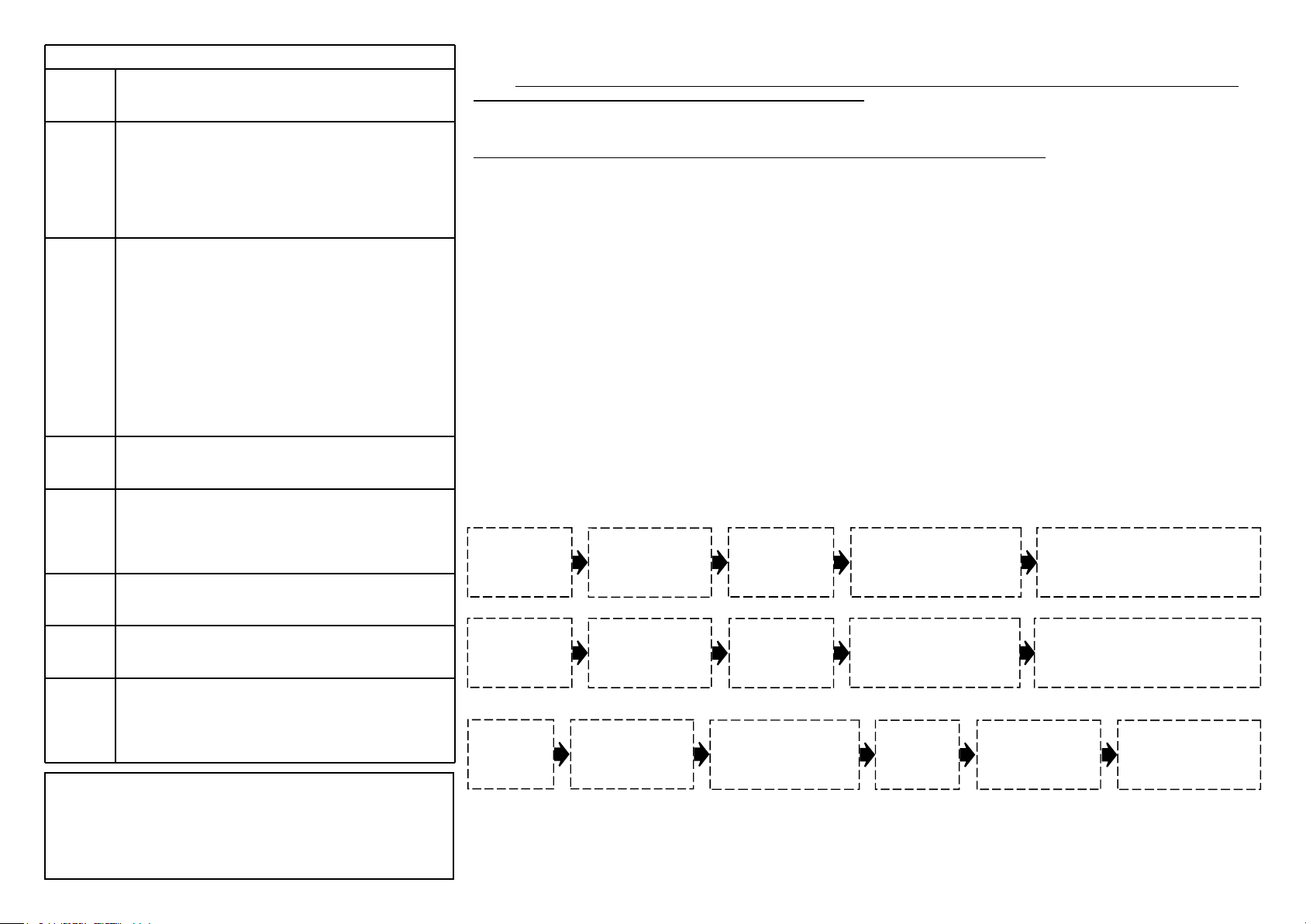
PROGRAMMAZIONE DELLA CORSA
La programmazione parte ad automazione chiusa, la prima manovra sarà l’apertura, in caso contrario invertire il senso di marcia
tramite lo scambio delle fasi del motore sulla morsettiera.
Essa potrà essere effettuata tramite i pulsanti posti sulla centrale GATE1 (PG1) e GATE2 (PG2), o tramite radiocomando precedentemente
programmato: il primo canale del TX è associato alla prima anta, il secondo canale del TX alla seconda. In caso di programmazione tramite
radiocomando,dovrà essere appreso solo il primo canale, il secondo verrà riconosciuto automaticamente.
Per entrare in programmazione premere P2 per 2 sec il led L3 si accende, a questo punto:
APPRENDIMENTO DOPPIA ANTA CON RALLENTAMENTO (DIP 7 ON)
Premere
la prima anta
inizia la manovra
di apertura
PG1
Attendere lo
sfasamento
desiderato in
apertura tra la prima
e la seconda anta
Premere
seconda anta
inizia la manovra
di apertura
PG2
la
Premere
che inizi il rallentamento
della prima anta e
rallentamento della seconda.
PG1
dove si vuole
PG2
per il
Automaticamente le due ante arrivate
a battuta arresteranno la corsa per
sensibilità amperometrica. In caso
contrario arrestarle con
PG1 ePG2
Segue con funzionamento in chiusura
Premere
seconda anta
inizia la manovra
di chiusura
PG2
Attendere lo
la
sfasamento
desiderato in chiusura
tra la seconda e la
prima anta
Premere
prima anta inizia
la manovra di
chiusura
PG1
la
Premere
che inizi il rallentamento della
seconda anta e
rallentamento della prima.
PG2
dove si vuole
PG1
per il
Automaticamente le due ante arrivate
a battuta arresteranno la corsa per
sensibilità amperometrica. In caso
contrario arrestarle con
PG1 ePG2
APPRENDIMENTO SINGOLA ANTA CON RALLENTAMENTO (DIP 7 ON)
Premere
l’anta inizia
la manovra
di apertura
PG1
Premere
si vuole l’inizio del
rallentamento
dell’ anta in apertura.
PG1
dove
L’anta arrivata a battuta
arresterà la corsa per
sensibilità amperometrica.
In caso contrario premere
PG1.
Premere
l’anta inizia la
manovra di
chiusura
PG1
Premere
vuole l’inizio del
rallentamento
dell’anta in chiusura .
PG1
dove si
L’anta arrivata a battuta
arresterà la corsa per
sensibilità
amperometrica. In caso
contrario premere
PG1.
APPRENDIMENTO SENZA RALLENTAMENTO (DIP 7 OFF)
Impostare l’opzione 7 in OFF per l’esclusione del rallentamento. Seguire la procedura desiderata elencata precedentemente
(apprendimenti con rallentamento singola o doppia anta) senza trasmettere gli impulsi per la gestione e l’inizio del rallentamento sia in apertura
che in chiusura. Quindi una volta trasmessi gli impulsi per l’inizio delle manovre esse dovranno terminare con gli impulsi di arresto della corsa.

E
OFF
OFF
ON
ON
+
-
SEC TRASF
24V
230V
LECTURA DE LOS LED
L1 L ED PO WER S e i lu mina cuand o la unida d est á ali menta da
L2 L ED RA DIO S e i lu mina al ac ceder a la memo ria r adio
L3 L ED PR OG. T IEMPO Se i lumin a par padea en l a pro grama ci ón
L4 L ED F. C. 2 CERRA NDO S e ilu mina cuand o el final de c arrer a es en NC
L5 L ED F. C. 2 ABRIE NDO S e ilu mina cuand o el final de c arrer a es en NC
L6 L ED FO TO CE RRAND O Se ilumi na cu ando el co ntacto de se gurid ad es cerr ado
L7 L ED F. C. 1 CERRA NDO S e ilu mina cuand o el final de c arrer a es en NC
L8 L ED F. C. 1 ABRIE NDO S e ilu mina cuand o el final de c arrer a es en NC
L7+L 8 LED STOP ambo s ilu minad o cua nd o e l STO P es en NC
L9 L ED PE ATONA L Se ilumi na cu ando recib es lo impu ls o de la peatona l
L10 LED S TART Se il umina cuan do re cibes un i mpulso
LÓGICA DE FUNCIONAMIENTO DE LA SEGURIDAD D.d.S. = Dispositivo de seguridada
IN. COSTA (15-17): Esto contacto protege la apertura y cierre
DIP 5 ON: El D.d.S. causar la interrupción de la manobria y la inversión para 2 seg.
DIP 5 OFF: El D.d.S. causar la interrupción de la manobria
En ambos casos, después de la desconexión comienza a reabrirs
IN. PHOTO (16-17): Este contacto protege solo en cierre.
En clausura, con el D.d.S. tendrá la inversión de la dirección.
STOP (21-23): El contacto abierto causará el paro inmediato de la automatización en cualquier situación.
AMPEROSTOP: En la apertura se para y invierte la maniobra por 2 seg. En el cierre para y invierte la maniobra.
EURO24M2
PROG
RADIO
L9
ANT
34 35
P1
J1
EXT
PG1
GATE1
M1
L10
STOP
PED
+
+
P2
+
PROG
TIME
L3
T1 T2 T3
ON
L2
1 2 3 4 5 6 7 8
DIP SWITCH
1-8
L4
L5 L6L7 L8
FCA2
FCC2
PHOTO
L1
+
FUSE
10A
30 31 32 33
FUSE
2A
1 2 3 4 5 6 7 8 9 31011 25 26 27 28 29 12 13 14 15 16 17 18 19 20 21 22 23 24
230V
AC
FLASH
N.O.
LAMP
N.O.
M1 M2
+
33V 0V 24V LOCK
PG2
GATE2
GATE2
M2
M2
VDS
FCC1
FCA1COSTA
TRIMMER T1
CRX
Regula la potencia y la
sensibilidad en trabajo
TRIMMER T2
Regula la potencia y la
sensibilidad durante la
desaceleración.
TRIMMER T3
ajusta el tiempo de
permanencia 3 a 120
segundos.
START
CARACTERÍSTICAS TÉCNICAS
Alimentación
Tensión Motor
Salida alimentación accesorios
Contacto Luz de Garaje
Tiempo espera cierre automático
Tiempo funcionamiento normal
Tiempo Luz de Garaje
Número de códigos
Gestion emissores
Frecuencia
Temperatura trabajo
Sensibilidad
Homologaciones
BORNES TIP DESCRIPCION
1-2 230Vac Entrada LINE 230Vac
3 Tierra
4-5 Libre Entrada DESTELLOS (contacto limpio 230V 10A)
6-7 Libre Entrada LUZ DE CORTESIA (contacto limpio 230V 10A)
8-9 24Vdc Entrada MOTOR 1
10-11 24Vdc Entrada MOTOR 2
12-14com N.C. Contacto final de carrera de cierre Mot.2 (Si usted no usa puede puentear)
13-14com N.C. Contacto final de carrera de abertura Mot.2 (Si usted no usa puede puentear)
15-17com N.C. Contacto costa/foto abertura (Si usted no usa puede puentear)
16-17com N.C. Contacto foto clausura (Si usted no usa puede puentear)
19-18com N.C. Contacto final de carrera de cierre Mot.1 (Si usted no usa puede puentear)
20-18com N.C. Contacto final de carrera de abertura Mot.1 (Si usted no usa puede puentear)
21-23com N.C.
22-23com N.O. Contacto PEATONAL
24-23com N.O. Contatto di START (Impulso alternativo APRE/STOP/CHIUDE/STOP)
25-26
negativo
27-26
negativo
28-29 12Vdc Alimentación electrocierras
30-31 24V ac Entrada secundario TRANSFORMADOR 24VAC
32-33 230Vac Entrada principal TRANSFORMADOR 230VAC
34-35 Entrada ANTENNA (35Signal)
33Vdc
24Vdc 24VDC Alimentación accesorios 24VDC 250mA
Contacto STOP (Si usted no usa puede puentear)
33VDC Alimentación accesorios 33VDC 250mA o conexion cargador
BOTON P1
Boton RADIO PROG para almacenar
emisores
BOTON P2
Boton PROG TIME para almacenar
la carrera
JUMPER J1 =
Posibilidad de insertar un receptor externo a través de
CRX conector, para aumentar el nr de código almacenado
o cambiar de frequencia.
Seleccion memoria Radio interna o externa
230V AC +/- 10%
24 Vdc
33V / 24V DC 250mA
Max 10A a 220V
5 a 120 sec
3 a 120 sec
180 sec
254 codici
Código fijo
433.92 / 868 Mhz
-20 a 70°C
Migliore –100dBm
Conf ETS 300-220/ETS 300-683
\ Roll-code
BOTON PG1
Boton GATE1 para la programacion de la carrera de
la hoja primera o comando de START
BOTON PG2
Boton GATE2 para la programacion de la carera de la
hoja segunda o comando para abrir el PEATONAL
INTERNA EXTERNA
insertar puente
:

SELECCIONAR LAS OPCIONES DIP-SWITCH
DIP1
ON
OFF
DIP2
ON
OFF
DIP3
ON
OFF
GESTION AMPEROSTOP EN MOVIMENTO SUAVE
En programaccion, en el movimiento suave
l'amperostop non trabaja (cuando quiera pulsar par
establecer el fin de carrera)
En funcionamento, en fase suave de abertura la
hoja afectada se para y en cierre para y invierte la
dirección de ambas hojas.
En programaccion, en el movimiento suave
l'amperostop non trabaja (cuando quiera pulsar par
establecer el fin de carrera)
En funcionamento, en fase suave de abertura la
hoja afectada se para y en cierre para y invierte la
dirección de ambas hojas.
DIP4
ON
OFF
DIP5
ON
OFF
DIP6
ON
OFF
DIP7
ON
OFF
DIP8
ON
OFF
CHIUSURA AUTOMATICA
Cierre automático activado
Cierre automático no activado
OPCIÓN DE CONDOMINIOS / PASO A PASO
Para cada pulso la automatizacion:
Abre-cierra en automatico o abre (durante la
operación de apertura cada pulsos tienen ningún
efecto.)
Para cada pulso la automatizacion:
(abre, para, cierra, abre)
HUELGA FUERTE PARA ELECTROCERRADURA
Activado
No activado
FUNCIONAMIENTO CONTACTO SEGURIDAD ABERTURA
Intervencion seguridad abertura, la central para el
movimiento e invierte por 2 sec
Intervencion seguridad abertura, la central para el
movimiento
FUNCION DESTELLOS
Luz intermitente
Luz fija
MOVIMIENTO SUAVE
Activado
No activado
EMPUJADO POR PRESIÓN EN CIERRE
LÓGICA DE FUNCIONAMIENTO DESTELLOS (DIP6 en ON)
EN ABERTURA: Se tendrá un intermitente lento
EN CIERRE: Se tendrá un intermitente veloz
EN PAUSA: Se tendrá el estado de luz fijo
EMPEÑO FOTO/COSTA: Al empeno se tendrá el apagamiento
El cuadro cada 180 min hace impulso de cierre a los
motores por 2 sec, evitándolo desviación de ambas
hojas.
Función desactivada
GENERALIDAD
Esta cuadro EURO24M2 es la instrumentación de control por sistemas a uno o dos hojas batiente con y sin final de carrera, por motor
alimentados a 24Vdc. La peculiaridad del EURO24M2 está en la regulacion de fuerza separada, por los trimmer T1 y T2 (el T1 regula la fuerza
durante la carrera en velocidad normal el T2 regula la fuerza en fase de velocidad mas suave. Trabajando sobre tales aparatos se puede
optimizar el funcionamiento del automatismo de manera tal de regresar en los parámetros de las actuales normas vigentes. La programación
de la carrera y los mandos está así en auto-aprender para simplificar los procedimientos de misa en función. Los aprendizajes de carrera de
los dos hojas se puede hacer en manera separada que poder tener dos tiempos de funcionamiento diferenciados.
La central administra la encuesta obstaculos por sensibilidad aperometrica en ambos los sentidos de marcha.
PROGRAMACIÓN DE LOS TRANSMISORES
Esta central puede administrar radiocomandos a código fijo y rolling code. Los dos sistemas no pueden ser administrados al mismo
tiempo, con el primer radiocomando programado ocurrirá la codifica del sistema.
El EURO24M2 puede administrar maximo 254 radiocomandos ROLLING CODE que tienes todos códigos diferentes.
En el caso de memorización TX a código fijo memorizar solo el primero TX y copiar otro TX de ello.
La programación de los radiocomandos ocurre a través de la presión de Boton P1 por 2sec, el led L2 se enciende, sucesivamente
comprimiendo la boton en el radiocomando el Led L2 indica lo ocurrida memorización. Después de 6 sec automáticamente la central saldrá de
la función de programación.
Abertura memoria radio por transmisor.(Posibilidad de memorizar transmisores del exterior sin la abertura y la visualización de la central,
por el boton escondido del TX ECO-R ya memorizado. Esto boton tiene la misma función del P1 PROG.RADIO situada sobre la central.
PROGRAMACCION PARA EL PASAJE PEATONAL
Para programar esta función pulsar el boton P1 por 2sec, soltar y volver a pulsar por 1 seg, el led L2 inicia a destellar, comprimir el boton
de emissores sobre la que se quiere memorizar la abertura peatonal; la central saldrá automáticamente de la función de programación.
La manobria por el pasaje peatonal es solo para la primera hoja (MOTOR1).
CANCELACIÓN DE TODOS LOS CÓDIGOS PRESENTES EN MEMORIA
Pulsar Boton P1 por 6 sec a su liberación ocurrirá un veloz led L3,con el consiguiente apagamiento después de 6 sec del led L2.
PROGRAMACION DE CARRERA
La programación comienza con la puerta cerrada, la primera operación será la apertura.
Ella podrá ser efectuada por los pulsantes sitios sobre el cuadro PG1 (gate1) y PG2 (gate2), o por emessores anteriormente programado: el
primero canal del TX es asociado con la primera hojas, el segundo canal del TX a la segunda hojas. En caso de programación por emessores,
necesita sólo ser aprendido el primero canal, el segundo será reconocido automáticamente.
Para entrar en programación pulsar P2 por 2 sec el led L3 se ilumina, ahora puede hacer:
APRENDIZAJE DOBLA HOJA CON MOVIMIENTO SUAVE, DIP 7 ON:
Pulsar
PG1
primero MOTOR1
inicia la maniobra
de abertura
el
Esperar el desfase
deseado en abertura
entre el la primera y
segunda hoja
Pulsar
PG2
segundo MOTOR2
inicia la maniobra
de abertura
el
inicio de movimento suave para
el MOTOR1, despues pulsar
para iniciar el movimento suave
para el MOTOR2.
donde usted quiera el
PG2
Automáticamente los dos hojas
llegados a golpe pararan la carrera
por sensibilidad amperometrica.
En caso contrario puede pararle con
Boton PG1 y PG2
Pulsar
PG1
Sigue con funcionamiento en cierre:
Pulsar
PG2
segundo
inicia la maniobra
de cierre
el
MOTOR
Esperar el desfase
deseado en cierre
2
entre el la
segundaprimera y
primera hoja
Pulsar PG1 el
primeroMOTOR1
inicia la maniobra
de cierre
Pulsar
PG2
inicio de movimento suave para el
MOTOR2, despues pulsar
para iniciar el movimento suave
para el MOTOR1
donde usted quiera el
PG1
Automáticamente los dos hojas
llegados a golpe pararan la carrera por
sensibilidad amperometrica.
En caso contrario puede pararle con
Boton
PG1 y PG2
APRENDIZAJE UNA SOLA HOJA CON MOVIMIENTO SUAVE, DIP 7 ON:
Pulsar
PG1
MOTOR1 inicia
la maniobra de
abertura
el
Pulsar
PG1
usted quiera el
inicio de movimento
suave para el
MOTOR1.
donde
Automáticamente la hoja
llegada a golpe para la carrera
por sensibilidad amperometrica.
En caso contrario puede parar
con Boton
PG1
Pulsar
PG1
el MOTOR1
inicia la
maniobra de
cierre
Pulsar
PG1
usted quiera el inicio
de movimento suave
para el MOTOR1, en
cierre
donde
Automáticamente la hoja
llegada a golpe para la carrera
por sensibilidad
En caso contrario puede parar
con Boton
amperometrica
PG1
APRENDIZAJE SIN CON MOVIMIENTO SUAVE, DIP 7 OFF
Programar la opción 7 en OFF por la exclusión de la disminución de velocidad. Seguir el procedimiento deseado enumerado anteriormente,
aprendizajes con disminución de velocidad individual o doble postigo, sin transmitir los impulsos por la gestión y el principio de la disminución
de velocidad sea en abertura que en cierre. Luego una vez transmitidos los impulsos por el principio de las maniobras ellas tendrán que
acabar con los impulsos de detención de la carrera.
.

25-26
negativo
OFF
OFF
ON
ON
+
-
GB
SEC TRASF
24V
230V
1 2 3 4 5 6 7 8 9 31011 25 26 27 28 29 12 13 14 15 16 17 18 19 20 21 22 23 24
230V
AC
LED STATE
L1 STATE Led Lights when the unit is powered
L2 Led RADIO ON when accessing memory in radio
L3 LED PROG. TIMES on flashing programming
L4 Led F.C. 2 CLOSING on when the switch is in N.C.
L5 Led F.C. 2 OPENING on when the switch is in N.C.
L6 Led PHOTO CLOSING on with the safety contact closed
L7 Led F.C. 1 CLOSING on when the switch and in N.C.
L8 Led F.C. 1 OPENING on when the switch and in N.C.
L7 + L8 Led STOP both on when the stop and NC
L9 PEDESTRIAN Led lights when take a pulse pedestrian
L10 Led START on when you give an impulse
OPERATION LOGIC OF THE SAFETY
Safety band Terminal 15-17 -This contact protects opening and closing.
DIP 5 ON: When there is an obstacle, the engine stop and reverse for 2 sec.
DIP 5 OFF: When there is an obstacle engine STOP
In both cases after the disengagement resumes the opening.
Photocells Terminal 16-17 - This contact protects only in closing
In closing when there is an obstacle engine STOP
Stop Terminal 21-23 - The contact if open will cause the immediate arrest of the automation in any situation.
AMPEROSTOP: In the opening stops and reverses the operation for 2sec. In closing stops and reverses direction.
EURO24M2
+
L1
+
30 31 32 33
FUSE
2A
FLASH
N.O.
FUSE
10A
LAMP
N.O.
+
M1 M2
+
+
PROG
TIME
P2
L3
33V 0V 24V LOCK
CRX
VDS
T1 T2 T3
ON
L2
1 2 3 4 5 6 7 8
DIP SWITCH
1-8
PG2
GATE2
GATE2
M2
M2
L4
L5 L6L7 L8
FCA2
FCC2
PHOTO
FCA1COSTA
TRIMMER T1
The Trimmer Power regulates
the power and sensitivity in
working.
TRIMMER T2
The Trimmer Power Slow
regulates the power and
sensitivity in slow down mode.
TRIMMER T3
The Trimmer Break regulates the
break time from 3 to 120 sec
FCC1
PROG
RADIO
L9
ANT
34 35
P1
J1
EXT
PG1
GATE1
M1
L10
PED
STOP
START
TECHNICAL FEATURES
POWER
POWER ENGINE
OUTPUT ACCESORIES
OUTPUT FLASH, OUTPUT COURTESY LIGHT
TIME FOR AUTOMATIC CLOSE
TIME FOR MANEUVER
TIME FOR COURTESY LIGHT
NR CODES STORABLE
TRANSMITERS TYPE
FREQUENCY
TEMPERATURE TO WORK
SENSIBILITY
HOMOLOGATION
TERMINAL TIP DESCRIPTION
1-2 230Vac Power 230V a c
3 Ground
4-5 Free FLASH (max output 230V 10A)
6-7 Free LAMP of courtesy (max output Max 230V 10A)
8-9 24Vdc ENGINE1
10-11 24Vdc ENGINE2
12-14com N.C. Limit switch closing ENGINE2
13-14com N.C. Limit switch opening ENGINE2
15-17com N.C. Safety band or opening photocells(if not use make the bridge
16-17com N.C. Closing photocells
19-18com N.C. Limit switch closing ENGINE1
20-18com N.C. Limit switch opening ENGINE1
21-23com N.C.
22-23com N.O. PEDESTRIAN contact
24-23com N.O. START contact
33Vdc
27-26
negativo
28-29 12Vdc Electric lock
30-31 24Vac Secondary input Transfomator 24Vac
32-33 230Vac Primary input Transformator 230Vac
34-35 Input Antenna (35 signal)
24Vdc Power service or accessories (output 24Vdc 250mA)
STOP contact (
Power service or battery charger (output 33Vdc 250mA)
BUTTON P1
RADIO PROG, for storage remote controls
BUTTON P2
PROG TIME, for storage the stroke
JUMPER J1 =
You can insert the external receivers with the connector CRX. So you
can increase the memory or change the frequency.
Insert bridge.
Selection storage radio INTERNAL EXTERNAL
230V AC +/- 10%
24 Vdc
33V / 24V DC 250mA
Max 10A a 230V
5 a 120 sec
3 a 120 sec
180 sec
254 code
Fix\ Roll-code
433.92 / 868 Mhz
-20 a 70°C
Better off –100dBm
Conf ETS 300-220/ETS 300-683
(if not use make the bridge)
(if not use make the bridge)
(if not use make the bridge)
(if not use make the bridge)
(if not use make the bridge)
if not use make the bridge
)
BUTTON PG1
GATE1 For the programming stroke of the first leaf
or start command.
BUTTON PG2
GATE2 For the programming stroke of the second
leaf or pedestrian opening.
INTERNAL EXTERNAL
)

ALL DIP-SWITCH:
DIP1
ON
OFF
DIP2
ON
OFF
DIP3
ON
OFF
MANAGE AMPEROSTOP IN SLOW DOWN PHASE
In programming mode, during the slowdown the
amperostop not intervene. (Give a impulse to store
the end of the stroke)
In operation, during slow down phase opening the
gate stops only interested, in closing stops and
reverses the direction of both leaves.
In programming mode, during the slowdown the
amperostop storage the end stroke.
In operation, during the slow down phase, in
opening, stop and reverse the stroke for 2 sec; in
closing stops and reverses the direction of both
leaves.
DIP4
ON
OFF
DIP5
ON
OFF
DIP6
ON
OFF
DIP7
ON
OFF
DIP8
ON
OFF
AUTOMATIC CLOSING
Automatic closing activated
Automatic closing not actived
CONDOMINIUM / STEP BY STEP
The automation will end the operation always on end
switches, in opening does not accept pulses, in
closing a pulse will cause the reverse.
For each pulse automation will stop
(OPEN-STOP-CLOSE-STOP)
STRIKE STRONG FOR ELECTRICLOCK
Activate
Not activate
CONTACT SAFETY IN OPENING
Opening safety intervention, the central blocks
movement and invert for 2 sec
Opening safety intervention, the central blocks
movement
FLASHING FUNCTION
Intermittent light
Steady light
SLOW DOWN
Activate
Not activate
IMPETUS FOR PRESS IN CLOSING
FLASHING OPERATION WITH DIP6 ON
IN OPENING: Flash slow
IN CLOSING: Flash fast
IN PAUSE: Steady light
PHOTOCELL ENGAGED: Turn off
The central ON every 180 min gives a closing
impulse engines for 2 seconds, avoiding the
deviation of the leaves from the stop.
Function off
GENERAL INFORMATION
The control board EURO24M2 can manage systems to one or two swing with or without limitswitch, for motor fed to 24Vdc. The peculiarity of
the EURO24M2 is in the regulation of separate torque between 2 swing, through the trimmers T1 and T2 (the T1 regulates the torque during
the run in normal speed the T2 it regulates the torque in slow down phase).
The planning of the stroke and the remote controls is in self-learning so to simplify the procedures of put in operation. The learnings of run of
the shutters happen in separate way so that to be able to have two times of operation differentiated. In opening and closing the EURO24M2
manage the obstacle by amperostop sensitivity
PROGRAMMING REMOTE CONTROL
The control unit is able to handle radio fixed code and rolling code. The two systems can not be managed simultaneously, but with the first
remote control will be programmed encoding system.
The EURO24M2 can handle 254 transmitters ROLLING CODE.
The programming of the transmitters is done by pressing the P1 for 2sec, the LED L2 turns on, then pressing the button of the remote will flash
twice to indicate the LED L2 is stored in memory.
After 6 seconds automatically central will exit the programming function.
PROGRAMMING PEDESTRIAN MODE (by remote control)
To program this function push the P1 button for 2sec, release and press again for 1 second, the LED L2 begins to flash at this moment press
button remote control where you want stored pedestrian opening. This mode it's possible only with Engine1.
After stored, automatically control board will exit the programming mode.
CANCELLATION OF ALL CODES IN MEMORY
Press and hold the P1 for 6 seconds when it is released there will be a quick flash of the LED L3, with consequent turning off after 6 seconds of
LED L2.
PROGRAMMING:
The programming starts with the gate closed, the first operation will be the opening, otherwise reverse the direction of travel through
the exchange of the motor phases on the terminal.
It can be made via the buttons on the control panel GATE1 (PG1) and Gate2 (PG2), or by remote control previously programmed: the first
channel of the TX is associated with the first door, the second channel of the TX to the second. In case of programming via
remote control, must be learned only the first channel, the second will be recognized automatically.
To enter the programming press P2 for 2 sec LED L3 lights up, at this point:
WITH SLOW DOWN (ON OPTION 7)
Push PG1
engine1 start
opening
Await for the
desired start for the
second leaf and
press PG2, now
engine2 starts.
Programming for closing
Push PG2 for
start the closing
engine2
Await for the desired
start for the engine1
and press PG1, now
engine1 starts.
Push PG1 when you want
slow down Engine1 and push
PG2 when you want slow
down Engine2
push PG2 when you
want slow down Engine2
and push PG1 when you
want slow down Engine1
automatically the 2 gate come to stop
the stroke for the amperometric
sensitivity if its do not stop push PG1
for stop engine1 and push PG2 for
stop engine2
automatically the 2 gate come to stop
the stroke for the amperometric
sensitivity if its do not stop push PG2
for stop engine2 and push PG1 for
stop engine1
now you have
programmed the
opening
now you have
programmed the
closing
SINGLE GATE WITH SLOW DOWN (ON OPTION 7)
Push PG1
engine1 start
opening
Push PG1
when you
want slow
down Engine1
Push
PG1 for
stop
engine1
Now you have
programmed the
opening
Programming for
closing
Push PG1
for start the
closing
engine2
Press PG1,
now
engine1
starts
closing
Push PG1
when you
want slow
down Engine1
now you have
programmed the
closing
WITHOUT SLOW DOWN (OFF OPTION 7)
It is same procedure but you do not give impulse for start the slow down phase. So after the pulse to the start of the stroke, the control panel
will only receive the impulse of the arrest of the race.

I nostri prodotti se installati da personale specializzato idoneo alla
valutazione dei rischi, rispondono alle normative UNI EN 12453-EN 12445
UNI
EN
Il marchio CE è conforme alla direttiva europea CEE 89/336 + 93/68 D.L.04/12/1992 n.476
El marcaje CE de este dispositivoindiva que cumple con la directiva europea
|
The CE mark complies with EEC European directiva 89/336 + 93/68 D.L.04/12/1992 n.476
I dati e le immagini sono puramente indicativi
VDS si riserva il diritto di modificare in qualsiasi momento le caratteristiche dei prodotti
descritti a suo insindacabile giudizio, senza alcun preavviso.
Los datos y las imágenes son orientativos
VDS se reserva el derecho de modificar en cualquier momento de las características de los
productos descritos en su única discreción, sin previo aviso.
Nuestros productos si instalados por personal cualificado capaz de la
evaluaccion de riesgos, cumplen con la norma UNI EN 12453, EN 12445
Our products if installed by qualified personnel capable to evaluate
risks, comply with norms UNI EN 12453, EN 12445
CEE 89/336 + 93/68 D.L.04/12/1992 n.476
The data and images are for guidance only
VDS reserves the right to change at any time characteristics of the products described in its sole
discretion, without notice.
CONTACTS:
AUTOMAZIONE ACCESSI
MADE IN ITALY
Via Circolare p.i.p. N° 10
65010 Santa Teresa di Spoltore (PE) - ITALY
Tel. +39 085 4971946 - FAX +39 085 4973849
www.vdsconsorzio.it - vds@vdsconsorzio.it
 Loading...