

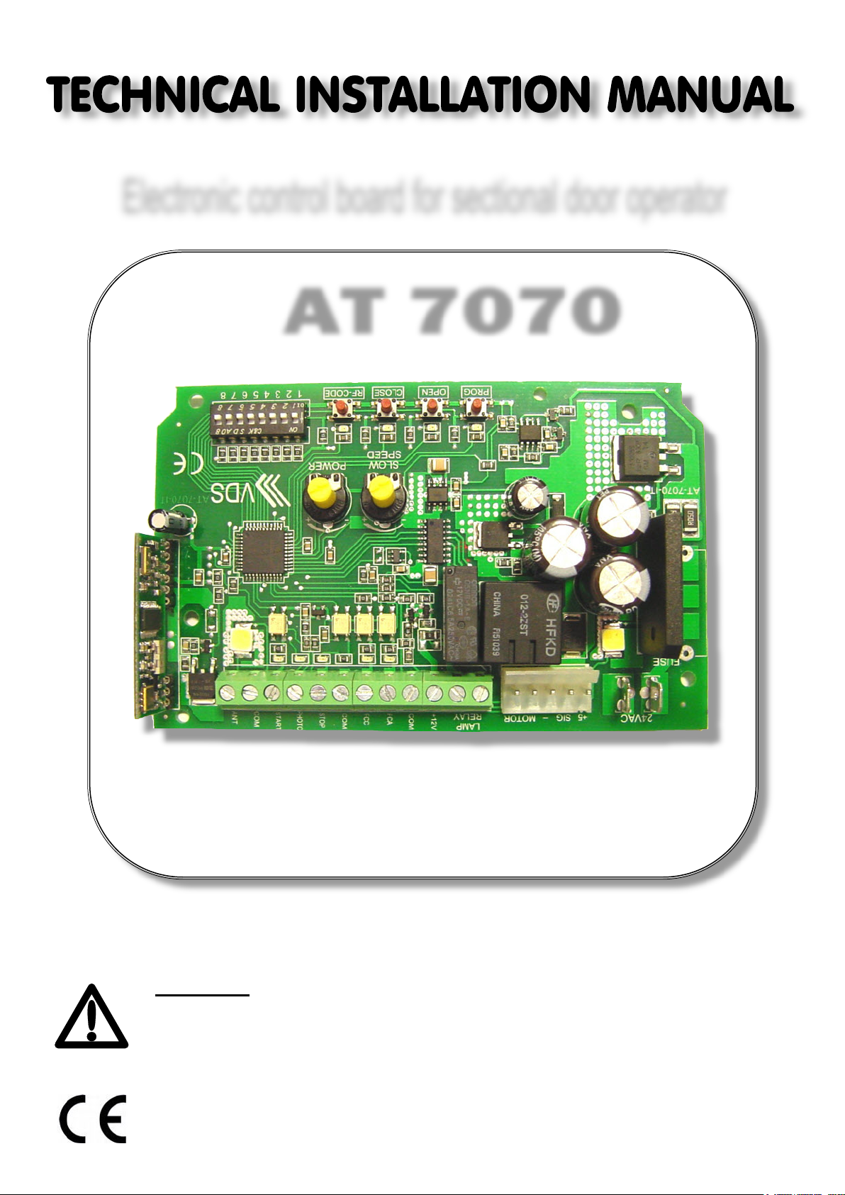
Electronic control board for sectional door operator
AT 7070
WARNING!! Before installing, thoroughly read this manual that is an integral
part of the pack
Our products if installed by qualified personnel capable to evaluate risks,
comply with norms UNI EN 12453, EN 12445
The CE mark conforms to European directive
EEC 89/336 + 92/31 + 93/68 D.L. 04/12/1992 N. 476.

1
Antenna
2
Start-stop-photocell common contact
1 mm²
3
Start contact N.O.
1 mm²
4
Photocell contact N. C. (put a jumper if nor used)
1 mm²
5
Stop contact N. C. (put a jumper if nor used)
1 mm²
6
Limit switches common contact
1 mm²
7
Closure limit switch contact N.C. (put a jumper if nor used)
1 mm²
9
Accessory power supply common
1 mm²
10
+ 12Vdc accessory power supply (photocells)
1 mm²
LAY OUT
RF CODE CLOSE OPEN PROG
1 2 3 4ON5 6 7 8
1 2 3 4
POWER
SLOW
SPEED
LED
TR2
FCC
+
LAMP
+12V
RELAY
COM
FCA
LED
10
ANT
+
TR1
LED
5 6 7 8 9
START
COM
PHOTO
COM
STOP
1 2 3 4 5 6 7 8 9 10 12
11 13
MOTOR
14
-
15
LED
10
SIG +5
16
17
24Vac
18
19
ELECTRICAL CONNECTION
8 Opening limit switch contact N.C. (put a jumper if nor used) 1 mm²
11-12 Flashing light free contact 1 mm²
13-14 Motor connection 24 Vdc
15 Encoder connection Negative
16 Encoder connection signal
17 Encoder connection +5V
18-19 Power Input 24 Vac (Transformer)
1 mm²
1 mm²
1 mm²
1 mm²
1,5 mm²
N.O. = Normally Open Contact N.C. = Normally Closed Contact
AUTOMATIC CLOSING:
Door closes automatically after waiting the a.c. time.
Door does not close automatically.
SAFETY FUNCTION (photocell):
ANALOG Contact (8.2KΩ)
N.C Contact (put a jumper if not used)
COURTESY LIGHT (LED 10):
Switched off
Switched on (with sthe START command, LED work for 30 sec)
FLASHING LIGHT OUTPUT (LAMP RELAY):
Light blinks until the operator is running or waiting for automatic closing.
It turns off after 30 seconds the operator stop.
Light is fix until the operator is running or waiting for automatic closing.
It turns off after 30 seconds the operator stop
SLOW START CLOSING
The automation during closing start at slow speed.
The automation during closing start at normal speed.
OPERATOR RUNNING DIRECTION:
Normale polarity
Reversed polarity
LED MEANINGS TABLE
N° LED
N° LED
1 RADIO
2 CLOSE
3 OPEN
4 PROGRAMMING
5 START
ON ON ON ON
1 2 3 4
DIP 1
ON
OFF
DIP 4
ON
ON ON ON ON
5 6 7 8
DESCRIPTION
DIP SWITCHES FUNCTIONS
DESCRIPTION
6 PHOTOCELL
7 STOP
8 CLOSURE LIMIT SWITCH
9 OPENING LIMIT SWITCH
10 COURTESY LIGHT
DIP 5
DIP 6
DIP 7
DIP 8
OFF
ON
OFF
ON
OFF
ON
OFF
ON
OFF
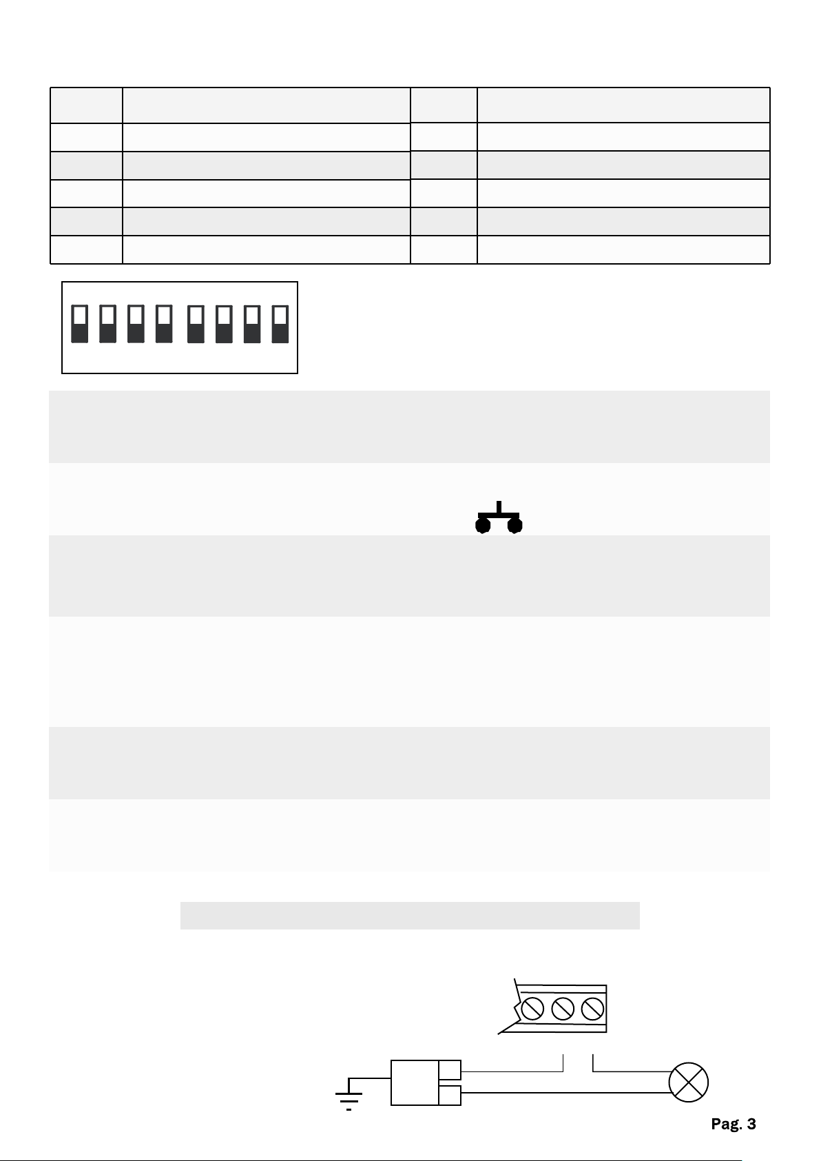
FLASHING LIGHT CONNECTION
Flashing light output relay (terminals 11-12)
Ground
Power supply
230V
L
N
+12V
11 12
LAMP
RELAY
LAMP
230V

AMPEROSTOP SENSIBILITY SETTING (ANTI CRUSHING)
To adjust the sensibility of the amperostop do the following :
Before programming stroke :
Ÿ Set the dip switch N ° 2-3 (look table)
- +
Ÿ Adjust the trimmer TR1 in halfway
Ÿ Program the stroke (see pag 5)
Ÿ Adjust trimmer TR1 so that the sensibility of the amperostop is adequate to the proper
functioning of the operator
Increase trimmer toward + to provide more
strength to the operator and less sensibility
- +
to the intervention of the amperostop
TR1
Increase trimmer toward - to provide less
strength to the operator and more sensibility
to the intervention of the amperostop
Sensibility amperostop Dip 2 Dip 3
100%
OFF OFF
TR1
75%
50%
25%
ON OFF
OFF ON
ON ON
SLOWING DOWN ADJUSTMENT
To adjust the slowing down speed :
Before programming stroke :
Ÿ Open the door with OPEN button and adjust trimmer TR2, to have the required speed.
Increase trimmer toward + to increase the
speed
- +
Increase trimmer toward - to decrease the
speed
TR2

RADIO TRANSMITTERS PROGRAMMING
Ÿ CODING : This control panel allows the storage of fix code and rolling code also simultaneously.
Ÿ PROGRAMMING:
Press RF-CODE button , LED lights for 10 seconds, press the transmitter button
you want to program. programming is completed.
Ÿ DELETING CODES:
To delete all codes in memory hold RF-CODE for 10 seconds until
LED begins to blink. the operation is completed
STROKE PROGRAMMING
WITH SLOW DOWN IN START CLOSING (DIP SWITCH 7 ON)
Ÿ Press OPEN button, bring the door to the desired opening and adjust the opening limit switch.
Ÿ Press CLOSE button, bring the door to the closure.
(NOTE : If connected, adjust the closure limit switch)
Ÿ Press PROG button for 2 seconds, LED blinks.
Ÿ Give a START impulse from button or radio transmitter, the door starts opening fast
Ÿ Give a second START imulse when you want to start the slowing down in opening, the door
stops once arrived to the opening limit switch.
Ÿ With automatic closure inserted, wait the desired time with the door open.
Ÿ Give a START impulse, door begins to close in slowing down
Ÿ Give a second START impulse, door begins to close faster.
Ÿ Give a third START impulse when you want to start the slowing down in closing
Ÿ Once arrived in closure the door memorizes the closed position.
WITHOUT SLOW DOWN IN START CLOSING (DIP SWITCH 7 OFF)
Ÿ Press OPEN button, bring the door to the desired opening and adjust the opening limit switch.
Ÿ Press CLOSE button, bring the door to the closure.
(NOTE : If connected, adjust the closure limit switch)
Ÿ Press PROG button for 2 seconds, LED blinks.
Ÿ Give a START impulse from button or radio transmitter, the door starts opening fast
Ÿ Give a second START imulse when you want to start the slowing down in opening, the door
stops once arrived to the opening limit switch.
Ÿ With automatic closure inserted, wait the desired time with the door open.
Ÿ Give a START impulse, door begins to fast close
Ÿ Give a second impulse when you want to start the slowing down in closing
Ÿ Once arrived in closure the door memorizes the closed position.

SAFETY DEVICES FUNCTION
PHOTOCELL (terminal 2-4)
Occupancy of photocell causes :
Ÿ Opening : no effect
Ÿ Closing : immediate stop and return to the opening operation.
AMPEROSTOP FUNCTION
Opening :
Ÿ Blocking the movement of the door
Closing :
Block ing and reverse in opening the movement of the door
START COMMAND FUNCTION
A START impluse by button or radio transmitter, with closed door, has the following function:
Ÿ STEP BY STEP: OPEN → STOP → CLOSE → STOP → OPEN
Ÿ AUTOMATIC: OPEN → STOP → AUTOMATIC CLOSURE O CLOSURE WITH IMPULSE →
STOP → OPEN


The data and images are for guidance only
reserves the right to change at any time characteristics of the products described in its sole
discretion, without notice.
CONTACTS :
Via Circolare p.i.p. N° 10
AUTOMAZIONE ACCESSI
MADE IN ITALY
65010 Santa Teresa di Spoltore (PE) - ITALY
Tel. +39 085 4971946 - FAX +39 085 4973849
www.vdsconsorzio.it - vds@vdsconsorzio.it
 Loading...