

Vaisala HMT370EX Installation Manual
M212306EN-B
EN
Installation and
Safety Guide
Intrinsically safe humidity and temperature
transmitter series
HMT370EX
DE
FR
NL
ES
PT
IT
HU
CS
PL
FI
ET
SV
NO
DA

PUBLISHED BY
Vaisala Oyj
Vanha Nurmijärventie 21, FI-01670 Vantaa, Finland
P.O. Box 26, FI-00421 Helsinki, Finland
+358 9 8949 1
Visit our Internet pages at www.vaisala.com.
© Vaisala Oyj 2021
No part of this document may be
reproduced, published or publicly
displayed in any form or by any means,
electronic or mechanical (including
photocopying), nor may its contents be
modified, translated, adapted, sold or
disclosed to a third party without prior
written permission of the copyright holder.
Translated documents and translated
portions of multilingual documents are
based on the original English versions. In
ambiguous cases, the English versions are
applicable, not the translations.
The contents of this document are subject
to change without prior notice.
Local rules and regulations may vary and
they shall take precedence over the
information contained in this document.
Vaisala makes no representations on this
document’s compliance with the local
rules and regulations applicable at any
given time, and hereby disclaims any and
all responsibilities related thereto.
This document does not create any legally
binding obligations for Vaisala towards
customers or end users. All legally binding
obligations and agreements are included
exclusively in the applicable supply
contract or the General Conditions of Sale
and General Conditions of Service of
Vaisala.
B C
G
D
E
F
H
1
35.5
[1.4]
141 [5.5]
I
J
A
160 [6.3]
124.5 [4.9]
115 [4.53]
HMP378
HMP377
HMP375
HMP374
HMP373
HMP371
59 [2.3]
56.5 [2.2]
115 [4.53]
141 [5.5]
mm
[in]
2
1
2
3
5
mA
V
Test Points
6
7
CH1
4
V
CH2
mA
2 × Ø 5.5 mm
1
3
M20×1.5
V
CH1
mA
Test Points
mA
V
CH2
M20×1.5
Do not remove this cover
!
A
2
Service Port
Use only in safe area
3
CH 1
4 ... 20 mA
12 ... 28 V
−
+
4
−
+
CH 2
4 ... 20 mA

4
3.5 Nm
5
6
7
4 mm2

Table of contents
Table of contents
English.............................................................................................................................................5
Deutsch......................................................................................................................................... 21
Français........................................................................................................................................39
Nederlands.................................................................................................................................. 57
Español.........................................................................................................................................75
Português.................................................................................................................................... 93
Italiano.......................................................................................................................................... 111
Magyar........................................................................................................................................ 129
Čeština........................................................................................................................................ 147
Polski........................................................................................................................................... 165
Suomi.......................................................................................................................................... 183
Eesti.............................................................................................................................................201
Svenska.......................................................................................................................................217
Norsk...........................................................................................................................................233
Dansk..........................................................................................................................................249
3

M212306EN-B
4

Chapter – Introduction to HMT370EX Series
1 Introduction to HMT370EX Series
Vaisala HUMICAP® Humidity and Temperature Transmitter Series HMT370EX is the ideal
solution for measuring humidity in hazardous areas. Intrinsically safe and robust, HMT370EX
operates safely and reliably even in the most hazardous areas, such as Zone 0. The nextgeneration HMT370EX transmitter can be used as a replacement for the long-running HMT360
transmitter series in all HMT360 applications.
HMT370EX can be installed directly in explosive areas. It can withstand continuous exposure to
potentially explosive environments that contain flammable gases or dust, and requires no
additional protective enclosures for operation in either gas or dust environments.
HMT370EX oers several probe options for dierent applications. Thanks to the detachable
probe module, probes can be easily replaced and removed for calibration outside the
hazardous area without removing the entire transmitter.
The transmitter has 2 analog current output channels (4 … 20 mA) for connection via safety
barriers. For easy-to-use access to configuration, diagnostics, and calibration and adjustment
functionalities, the probe and transmitter body can be connected to Vaisala Insight PC
software for configuration either together as one unit or separately.
1.1
Basic features and options
• Available measurement parameters: relative humidity (RH) and temperature (T)
•
Calculated measurement parameters include 1) : dew point temperature, wetbulb
temperature, absolute humidity, mixing ratio, water concentration, water mass
fraction, water vapor pressure, enthalpy, and oil/fuel moisture with special models
• Ex classification: IECEx and ATEX certified for use in Zone 0 and Zone 20 environments:
for full Ex classifications, see Table 1 (page 6).
• 2 analog outputs (4 … 20 mA, scalable, isolated)
• Display options: graphical LCD display or non-display model
• Power supply input: 12 … 28 V
• Compatible with Vaisala Insight PC software
ENGLISH
1.2
More information
For further information on using, configuring, and maintaining the transmitter after
installation, see HMT370EX User Guide (available at www.vaisala.com/HMT370EX).
1) Additional calculated parameters available: see product information at vaisala.com
5
M212306EN-B
2 Using HTM370EX Series transmitters in
hazardous locations
WARNING!
mandatory in a hazardous environment.
In hazardous environments, always connect the transmitters via galvanic isolators or Zener
barriers. A galvanic isolator or Zener barrier must also be used when the transmitter and probe
body are in a safe area, but the probe head is installed in a hazardous environment. For wiring
information, see the galvanic isolator and Zener barrier wiring diagrams included in this
document.
HMT370EX does not include a galvanic isolator or a Zener barrier. They can be ordered as
optional accessories from Vaisala.
WARNING!
hazardous locations as specified by the product classification. The personnel
installing, using, or maintaining HMT370EX transmitters are responsible for
determining the appropriate protection concept for the specific application
HMT370EX is used in, and that the hazardous area classification of the device
meets the requirements of the application.
WARNING!
protection provided by the equipment may be impaired.
HMT370EX series transmitters are certified for use in hazardous areas as defined by the
following classifications:
Table 1 HMT370EX series hazardous area classifications
Protected installation using galvanic isolators or Zener barriers is
HMT370EX series transmitters have been designed for use in
If the equipment is used in a manner not specified by Vaisala, the
Certification HMT370EX classification
IECEx 1) / ATEX
1) International certification
2) EU certification
6
2)
II 1 G Ex ia IIC T4 Ga
II 1 D Ex ia IIIC T
-40 °C ≤ T
≤ +60 °C
amb
200
85 °C Da

HMT370EX
1 2 31a
M20x1.5 M20x1.5
Chapter – Using HTM370EX Series transmitters in hazardous locations
CAUTION!
transmitters must have the required competencies for working in the hazardous
location, as defined by the applicable standards.
For information on the standards that apply to using HMT370EX based on the classification of
the device, see HMT370EX certification documentation and the declarations of conformity
related to HMT370EX at www.vaisala.com/declarationofconformity.
The personnel installing, operating, and maintaining HMT370EX
2.1 Guidelines for safe use in hazardous conditions
HMT370EX Series parts overview
ENGLISH
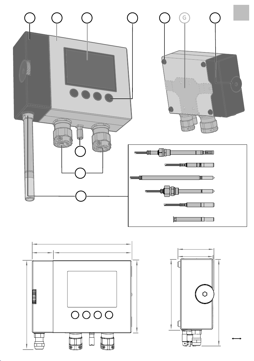
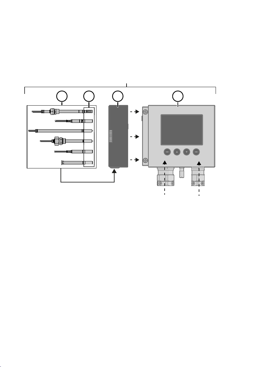
Figure 1 HMT370EX parts overview
HMT370EX Series transmitters consist of 3 main parts: the transmitter body, a detachable
probe body, and a probe head attached to the probe body, either directly or using a cable.
Figure 1 (page 7) shows the main parts.
Probe heads (for variant descriptions, see HMT370EX User Guide)
1
1a Probe head filters
2 Probe body
3 Transmitter body
7

M212306EN-B
The dierent probe head variants are designed for a range of applications, and have their own
specifications. Ensure that the transmitter body, probe body, and probe head are each placed
in an environment that matches the specification of the part. For allowed ambient temperature
ranges, see Table 2 (page 8).
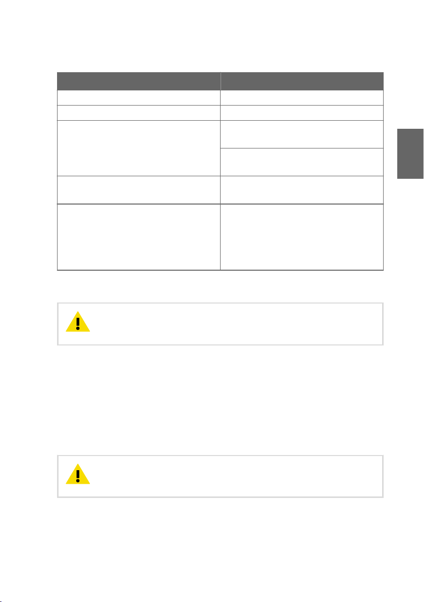
Table 2 Allowed ambient temperature ranges
Equipment part Allowed ambient temperature range
Transmitter body -40 °C … +60 °C (-40 … +140 °F)
Probe body -40 °C … +60 °C (-40 … +140 °F)
Probe heads HMP374, HMP375, HMP377, and
HMP378
Probe head HMP371 Temperature class T4:
Probe head HMP373 Temperature class T4:
Temperature class T4:
-70 °C … +120 °C (-94 … +248 °F)
Temperature class T3:
-70 °C … +180 °C (-94 … +356 °F)
-40 °C … +60 °C (-40 … +140 °F)
Rubber cable version:
-40 °C … +80 °C (-40 … +176 °F)
FEP cable version:
-40 °C … +120 °C (-40 … +248 °F)
2.1.1 Specific conditions of use
CAUTION!
to be ensured that sparks due to impact or friction do not occur.
Wiring requirements
• The cable glands and cables used for wiring the device must not impair the Ex protection.
• Unused lead-throughs must be sealed using Ex compliant plugs.
• Select a strain relief option that suits the application (either use cable glands that include
strain relief or install separate clamps: see IEC 60079-14).
CAUTION!
input before completing the wiring and closing the transmitter body.
8
With the installation of the equipment in Zone 0 Group II area it has
Connect only de-energized wires. Never switch on the power supply
mA
V
mA
V
CH1
CH2
A
Service Port
Use only in safe area
!
Do not remove this cover
1
2
Test Points
Chapter – Using HTM370EX Series transmitters in hazardous locations
Intrinsic safety
The overvoltage category of HMT370EX transmitters is I (non-mains equipment), and ambient
pollution degree is 4, as specified in IEC 60664-1. For intrinsically safe input parameters, see
Table 3 (page 9) .
Table 3 Intrinsically safe input parameters
Parameter Value Associated apparatus entity
parameters
U
i
I
i
P
i
C
i
L
i
28 VDC Uo ≤ U
100 mA Io ≤ I
700 mW Po ≤ P
i
i
i
12.1 nF Co ≥ Ci + C
16 µH Lo ≥ Li+ L
cable
cable
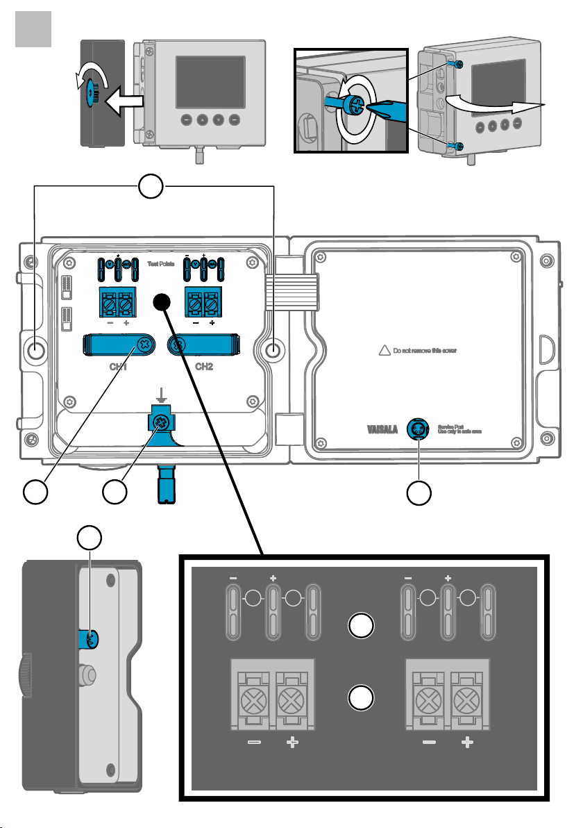
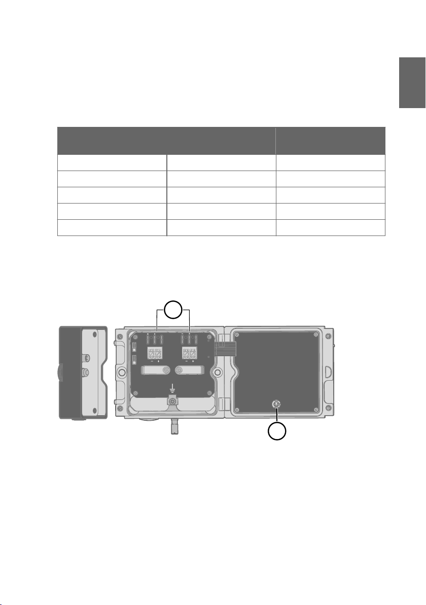
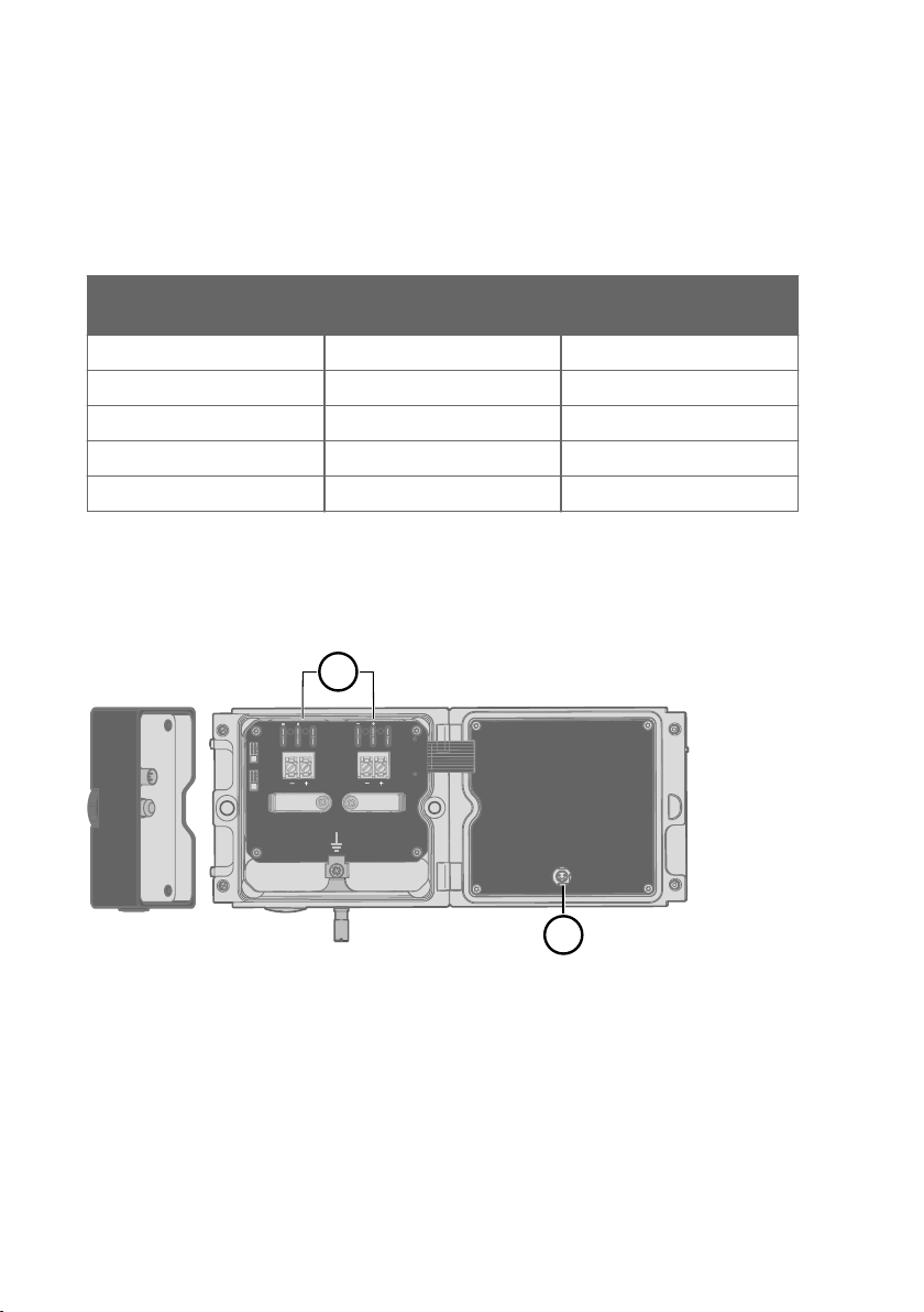
Using analog output test points
There are test points for measuring the voltages and currents of the analog outputs, located
above each screw terminal block as shown in Figure 2 (page 9). Accessing the test points on
the component board requires opening the transmitter enclosure.
ENGLISH
Figure 2 Location of test points and service port
Multimeter test points for analog output channels 1 and 2
1
2 Service port for PC connection
9
M212306EN-B
CAUTION!
The transmitter body enclosure must not be opened in an explosion
hazardous area, unless a safe work permit has been issued in accordance with
the standard IEC 60079-14. Either remove the transmitter from the hazardous
area before opening the enclosure, or ensure that an IEC 60079-14 compliant
safe work procedure has been implemented in the hazardous area.
Use an intrinsically safe multimeter that won't cause the intrinsically safe input parameters
listed in Table 3 (page 9) to be exceeded when it is connected in series (current measurement)
or parallel (voltage measurement) to the associated apparatus.
Using the service port
The service port (see Figure 2 (page 9)) must only be used in a safe area. Either remove the
transmitter from the hazardous area or ensure that a safe work procedure has been
implemented in the hazardous area. Only use the Vaisala accessory PC connection cable with
the service port.
Maintenance
The probe (includes probe body and head) can be detached and replaced by the user. The
probe head filter (see Figure 1 (page 7)) is also user-replaceable. For other maintenance
requirements, contact Vaisala.
CAUTION!
The probe can be detached and changed when HMT370EX is
powered. Any other live maintenance, including changing the probe head filter,
is not allowed.
The content in this chapter is maintained in the following separately tracked document:
Document ID: M212506EN Revision: A (25 Feb 2021)
10
Chapter – HMT370EX parts
3 HMT370EX parts
External parts
Items A … J refer to the external parts illustration page 1 in the beginning of the
document. Items 1 … 7 refer to the internal parts illustration page 2 in the
beginning of the document.
Table 4 External parts
Item Description
A Probe head (for HMP370EX probe head variant options, see HMT370EX User Guide)
B Detachable probe body
C Transmitter body (see Internal parts table)
D LCD display (in optional display model)
E Display user interface buttons (display model only)
F Wall pads (4 pcs)
G Mounting plate (optional)
H Probe body locking wheel
I Grounding terminal
J Lead-throughs for wiring (for cable gland and conduit options, see HMT370EX User
Guide)
ENGLISH
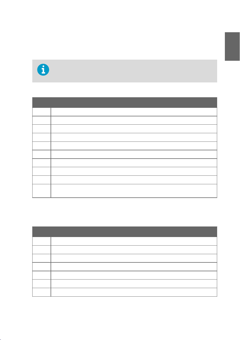
Internal parts
Table 5 Internal parts
Item Description
1 Holes for mounting screws
2 Cable fastening clamps
3 Transmitter grounding terminal
4 Transmitter service port (M8, requires Vaisala USB connection cable)
5 Probe body service port (M12, requires Vaisala USB connection cable)
6 Analog output channel 1 and 2 multimeter test points for current and voltage
7 Screw terminals for wiring analog output channels 1 and 2
11

4 Installation and wiring
M212306EN-B
WARNING!
ensure that an IEC 60079-14 compliant safe work procedure has been
implemented in the hazardous area.
WARNING!
be opened in a hazardous area. The probe can be detached and changed
when HMT370EX is powered. Any other live maintenance, including changing
the probe head filter, is not allowed.
The installation must be carried out in a safe area, or you must
When HMT370EX is powered, the transmitter enclosure must not
4.1 Installation preparations
Before starting the installation, check the following:
• Make sure that your installation site suits the Ex classification of the transmitter: see Table
1 (page 6).
• Review the hazardous area information in Guidelines for safe use in hazardous conditions
(page 7) for further information on Ex safety requirements related to HMT370EX and
specific conditions of use.
• Review the wiring diagrams included in this document for information on wiring using
either a galvanic isolator or a Zener barrier.
• Wiring with galvanic isolators (page 17)
• Wiring with Zener barriers (page 18)
• When selecting the cable glands and plugs for your application, make sure they are Ex
compliant. The glands and plugs must be water and dust tight.
Wiring information
WARNING!
mandatory in a hazardous environment.
CAUTION!
(CH1) must always be wired. The transmitter receives power through the
Channel 1 screw terminals, and does not power on if only Channel 2 (CH2) is
wired.
12
Protected installation using galvanic isolators or Zener barriers is
When planning the wiring of your application, note that Channel 1
1
2
Chapter – Installation and wiring
CAUTION!
minimum voltage in all conditions, measured at the transmitter screw terminals.
If the supply voltage is less than 12 VDC, the analog output current can be
erroneous.
It is recommended to use ferrules on the stripped wires to help ensure a secure
connection with the screw terminals.
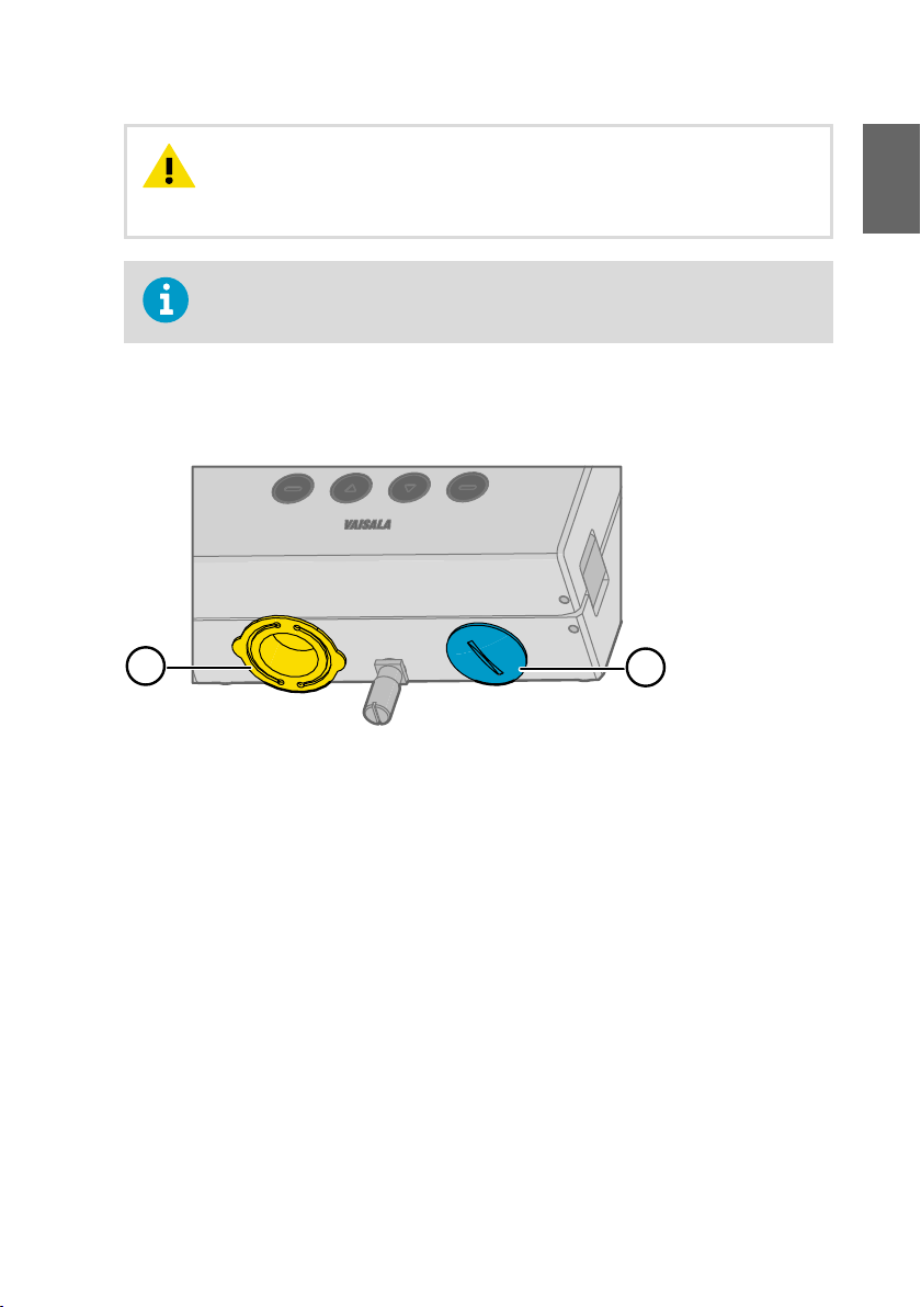
Lead-through selection and default plugs
HMT370EX comes delivered with 2 dierent plug types on the transmitter lead-throughs, as
shown in Figure 3 (page 13).
Figure 3 Default plugs in HMT370EX lead-throughs
Ensure that the transmitter is powered correctly. 12 VDC is the
ENGLISH
Removable plastic transport cover: must be replaced (fold sides of transport cover
1
together and pull out)
2 Metal sealing plug: can be used in final installation
The plastic transport cover (1) must always be replaced with an Ex compliant cable gland,
conduit, or seal when wiring HTM370EX. The metal sealing plug (2) can be left in place and
used in the final installation, if the right-hand lead-through is not used. For cable gland and
conduit options, see HMT370EX User Guide.
13

M212306EN-B
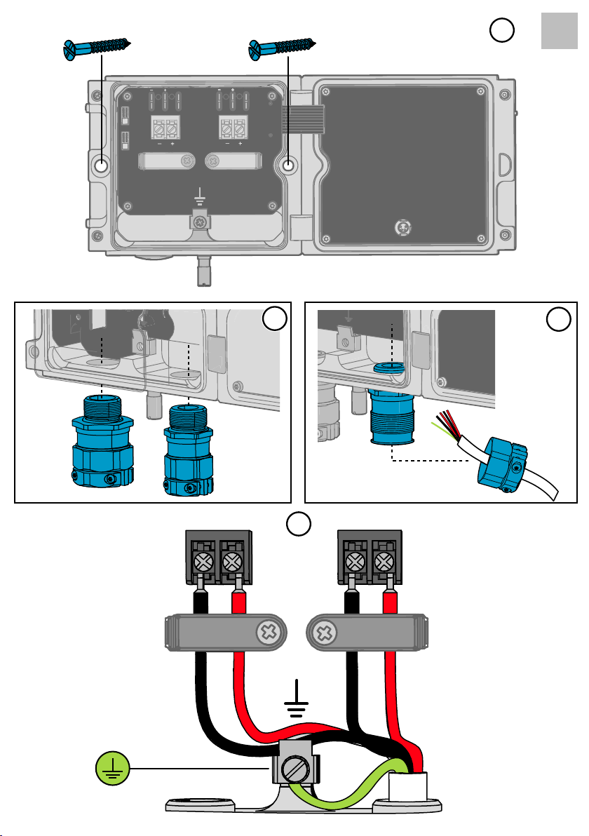
4.2 Installing HMT370EX
• Screws for mounting the transmitter:
• Installation directly through the transmitter body: 2 pcs Ø 5.5 mm screws
• Installation with optional mounting plate: 4 pcs Ø 5.5 mm screws and 2 pcs
M6 Allen screws
• Crosshead screwdriver for transmitter cover captive screws and wiring screw
terminals
• Flathead screwdriver for the grounding terminal
• Cable glands, conduits, and plugs as required in your application, and suitable
tools for attaching and tightening them
• Wire-cutting pliers
Optional:
• Crimping tool and wire ferrules
• Allen key (5 mm) for probe body locking wheel
• Ex-compliant multimeter for testing analog outputs
Steps 1 … 7 refer to illustrations 1 … 7 on illustration pages 3 and 4 in the beginning
of the document.
1. Select a surface (for example, a wall) for installing the transmitter. You can mount the
transmitter directly to the installation surface with 2 screws, or use an optional mounting
plate that attaches to the back of the transmitter.
a. Installation without mounting plate: attach the transmitter body directly to the
installation surface with 2 Ø 5.5 mm screws. The left-hand screw hole has extra
vertical space for adjusting the position of the transmitter after you have attached the
right-hand screw.
b. Installation with mounting plate: attach the mounting plate to the installation surface
with 4 Ø 5.5 mm screws, and then attach the transmitter to the mounting plate with 2
M6 Allen screws.
2. Attach cable glands (1 or 2) to the wiring lead-throughs as required in your application.
Note the cable gland requirements listed in Specific conditions of use (page 8).
• Both lead-throughs have M20x1.5 threads.
• Plug possible unused lead-throughs with Ex compliant seals.
• The glands and plugs must be water and dust tight.
14
Chapter – Installation and wiring
3. Prepare the cabling wires as required in your application (cabling either through 1 or 2
lead-throughs).
a. Strip the cable wires: it is recommended to attach ferrules to the contact ends of the
wires.
b. Open the cable gland and insert a suitable length of the cable inside the transmitter
through the cable gland.
c. Tighten the cable gland: refer to the instructions of the glands used in your
application for maximum tightness.
d. If your installation does not require using both lead-throughs, plug the unused lead-
through with an Ex compliant seal.
4. Connect the screw terminal wiring as required in your application. For protected
installation wiring diagrams, see Wiring with galvanic isolators (page 17) and Wiring with
Zener barriers (page 18).
a. Open the cable fastening clamps below the screw terminals and lead the cables to the
terminals through the clamps.
b. Connect the wires to the screw terminals.
Note that Channel 1 (CH1) must always be wired. The transmitter receives
power through the CH1 screw terminals, and does not power on if only
Channel 2 (CH2) is wired.
c. Adjust the length of the wires and close the cable fastening clamps so that they hold
the cables in place.
Optional: For instructions on testing the analog output level with a multimeter, see step 8.
5. Close the transmitter body cover and tighten the captive screws, and then attach the
probe body to the transmitter.
ENGLISH
It is sucient to tighten the probe body to finger tightness with the locking
wheel. To prevent detaching the probe body without tools, you can tighten
the locking wheel further with an Allen key (5 mm).
6. Mount the probe head to the area you want to measure in.
HMT370EX Series probes are designed for a variety of applications with
dierent installation requirements. For probe-specific installation
instructions, see HMT370EX User Guide.
7. Connect the grounding terminal on the bottom of the transmitter to the grounding
element of the installation site with a 4 mm2 grounding wire. After grounding the
transmitter, switch on the power supply input.
15
mA
Test Points
CH1
CH2
mA
V
V
+
−
20.0 mA
M212306EN-B
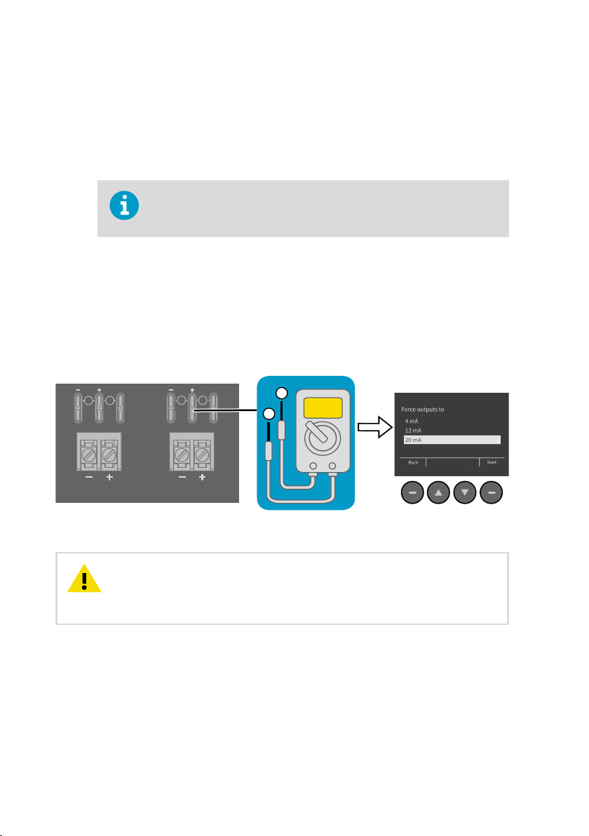
8. Optional: if you want to verify the output level of the analog output channels, test the
connection as follows:
a. Detach the probe body and open the transmitter cover.
b. Connect a multimeter to the mA testing points located above the output screw
terminals on the transmitter component board (see illustration page 2 in the
beginning of the document for the location of the terminals).
Always use an Ex compliant multimeter. The output parameters of the
multimeter must be compatible with the input parameters of the
transmitter.
c. Start the output test mode either by using the transmitter display interface, or, if
using a transmitter without a display, by connecting the transmitter to Insight PC
software. For instructions on using the output test mode with the display interface
and Insight PC software, see HMT370EX User Guide.
d. After verifying the output, remove the multimeter, close the transmitter cover, and
reattach the probe body.
Figure 4 Multimeter test point overview
CAUTION!
The service port (see Figure 2 (page 9)) must only be used in a safe
area. Either remove the transmitter from the hazardous area or ensure that a
safe work procedure has been implemented in the hazardous area. Only use the
Vaisala accessory PC connection cable with the service port.
16
mA
Test Points
mA
V
V
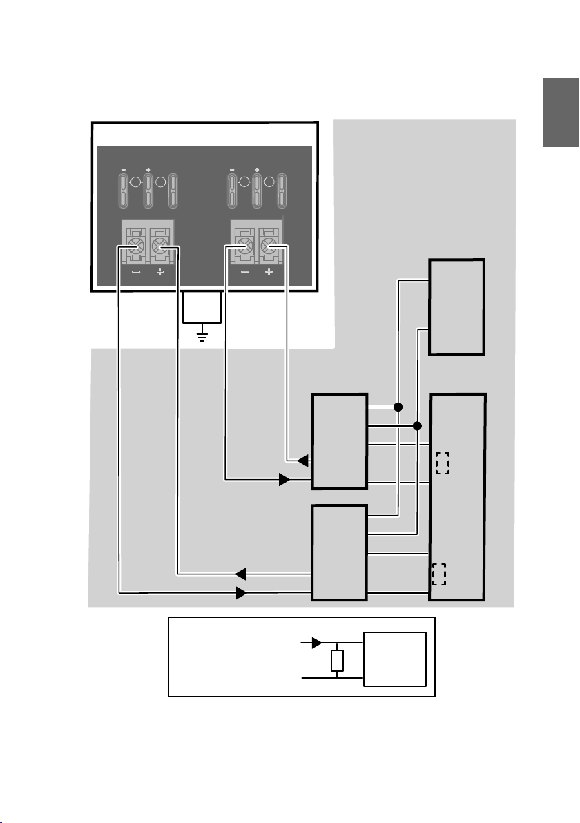
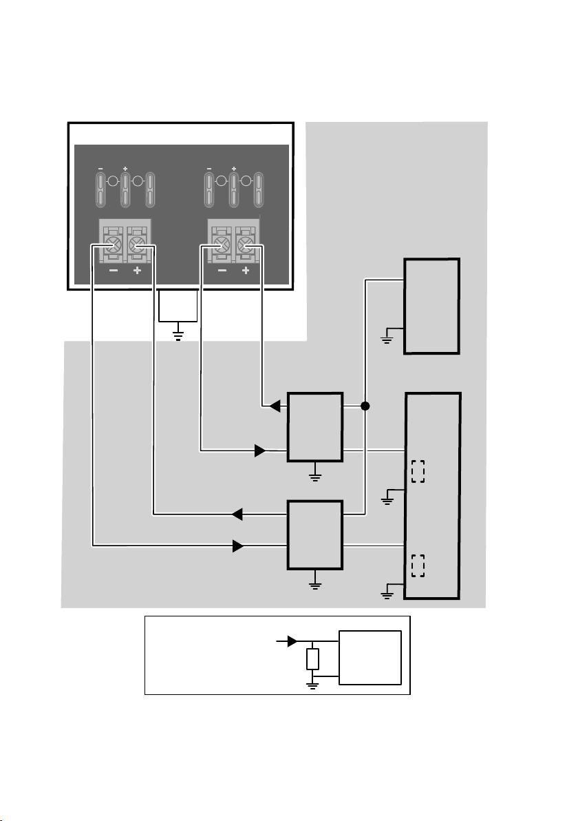
HAZARDOUS AREA
External
grounding
terminal
SAFE AREA
4 ... 20
mA
+
-
+
-
4 ... 20
mA
+
-
+
-
L
L
+
-
L
L
+
-
Intrinsically
safe certified
galvanic isolators
Controller
DC power supply
+
-
If the controller
uses voltage input,
use a shunt resistor:
+
-
4 ... 20 mA
Controller
U = I*RI
RI
+
-
+
-
Chapter – Installation and wiring
4.3 Wiring with galvanic isolators
ENGLISH
Figure 5 Wiring diagram with galvanic isolators
17
4.4 Wiring with Zener barriers
mA
Test Points
mA
V
V
HAZARDOUS AREA SAFE AREA
4 ... 20
mA
+-+
-
4 ... 20
mA
Intrinsically
safe certified
Zener barriers
Controller
DC power supply
+
-
+
-
If the controller
uses voltage input,
use a shunt resistor:
+
-
4 ... 20 mA
Controller
U = I*RI
RI
+-+
-
4 ... 20
mA
+
-
External
grounding
terminal
M212306EN-B
Figure 6 Wiring diagram with Zener barriers
18

Chapter – Installation and wiring
Maintenance and calibration services
Vaisala oers comprehensive customer care throughout the life cycle of our
measurement instruments and systems. Our factory services are provided
worldwide with fast deliveries. For more information, see www.vaisala.com/
calibration.
• Vaisala Online Store at store.vaisala.com is available for most countries. You
can browse the oering by product model and order the right accessories,
spare parts, or maintenance and calibration services.
• To contact your local maintenance and calibration expert, see
www.vaisala.com/contactus.
Warranty
For standard warranty terms and conditions, see www.vaisala.com/warranty.
Please observe that any such warranty may not be valid in case of damage due to normal wear
and tear, exceptional operating conditions, negligent handling or installation, or unauthorized
modifications. Please see the applicable supply contract or Conditions of Sale for details of the
warranty for each product.
Technical support
Contact Vaisala technical support at helpdesk@vaisala.com. Provide at least the
following supporting information as applicable:
• Product name, model, and serial number
• Software/Firmware version
• Name and location of the installation site
• Name and contact information of a technical person who can provide further
information on the problem
For more information, see www.vaisala.com/support.
ENGLISH
Recycling
Recycle all applicable material.
19

M212306EN-B
Follow the statutory regulations for disposing of the product and packaging.
20

Kapitel – Einführung zur Serie HMT370EX
1 Einführung zur Serie HMT370EX
Die Vaisala HUMICAP® Feuchte- und Temperaturmesswertgeber der Serie HMT370EX eignen
sich besonders zur Feuchtemessung in Gefahrenbereichen. Der eigensichere und robuste
HMT370EX arbeitet auch in stark explosionsgefährdeten Bereichen (z. B. Zone 0) sicher und
zuverlässig. Der Messwertgeber HMT370EX der neuen Generation kann in allen HMT360
Anwendungen als Ersatz für die Geräte der Messwertgeberbaureihe HMT360 verwendet
werden.
Der HMT370EX kann direkt in explosionsgefährdete Bereiche eingebaut werden. Er ist für den
dauerhaften Einsatz in explosionsgefährdeten Umgebungen geeignet, die entflammbare Gase
oder Stäube enthalten. Für den Betrieb in solchen Umgebungen sind keine zusätzlichen
Schutzgehäuse erforderlich.
Für den HMT370EX sind verschiedene Sonden für unterschiedliche Anwendungen erhältlich.
Dank des abnehmbaren Sondenmoduls lassen sich die Sonden einfach austauschen, um sie
außerhalb des Gefahrenbereichs kalibrieren zu können, ohne den Messwertgeber vollständig
ausbauen zu müssen.
Der Messwertgeber verfügt über 2 analoge Stromausgangskanäle (4 … 20 mA), die über
Sicherheitsbarrieren angeschlossen werden. Sonde und Messwertgebergehäuse können zur
Konfiguration zusammen als Einheit oder separat mit der Software Vaisala Insight PC
verbunden werden, die den benutzerfreundlichen Zugri auf Konfigurations-, Diagnose-,
Kalibrier- und Justierfunktionen ermöglicht.
1.1
Grundlegende Merkmale und Optionen
DEUTSCH
• Verfügbare Messgrößen: Relative Feuchte (rF) und Temperatur (T)
• Berechnete Messgrößen:1): Taupunkttemperatur, Feuchttemperatur, absolute Feuchte,
Mischungsverhältnis, Wasserkonzentration, Wassermassenanteil, Wasserdampfdruck,
Enthalpie und Feuchtegehalt in Öl/Kraftsto mit Spezialmodellen
• Ex-Klassifizierung: IECEx- und ATEX-zertifiziert für Umgebungen der Zonen 0 und 20:
vollständige Ex-Klassifizierungen siehe Tabelle 6 (Seite 22).
• 2 Analogausgänge (4 ... 20 mA, skalierbar, isoliert)
• Displayoptionen: Grafisches LC-Display oder Modell ohne Display
• Versorgungsspannungsbereich: 12 … 28 V
• Kompatibel mit der PC-Software Vaisala Insight
1.2
Weitere Informationen
Weitere Informationen zu Verwendung, Konfiguration und Wartung des Messwertgebers nach
dem Einbau enthält das HMT370EX User Guide (verfügbar unter www.vaisala.com/
HMT370EX).
1) Zusätzlich verfügbare berechnete Größen: siehe Produktinformationen unter vaisala.com
21
M212306EN-B
2 Verwenden von Messwertgebern der
Serie HMT370EX in Gefahrenbereichen
WARNUNG
Trennstufen oder Sicherheitsbarrieren erfolgen.
Schließen Sie die Messwertgeber in Gefahrenbereichen immer über Ex-i-Trennstufen oder
Sicherheitsbarrieren an. Eine Ex-i-Trennstufe oder Sicherheitsbarriere muss auch verwendet
werden, wenn sich Messwertgeber und Sondenkörper in einem sicheren Bereich befinden, der
Sondenkopf jedoch in einen Gefahrenbereich eingebaut wird. Informationen zur Verdrahtung
enthalten die Schaltpläne in diesem Dokument zu Ex-i-Trennstufen und Sicherheitsbarrieren.
Der HMT370EX enthält keine Ex-i-Trennstufe und keine Sicherheitsbarriere. Diese
Komponenten können als optionales Zubehör bei Vaisala bestellt werden.
WARNUNG
Gefahrenbereichen (gemäß Produktklassifizierung) entwickelt. Das für Einbau,
Nutzung und Wartung der HMT370EX Messwertgeber zuständige Personal ist
für die Einhaltung der erforderlichen Sicherheitsvorkehrungen im jeweiligen
Anwendungsbereich des HMT370EX verantwortlich und muss sicherstellen,
dass die Gefahrenbereichsklassifizierung des Geräts der betreenden
Anwendung entspricht.
WARNUNG
Weise verwendet wird, ist der ausrüstungsseitige Schutz möglicherweise
beeinträchtigt.
Messwertgeber der Serie HMT370EX sind gemäß den folgenden Klassifizierungen für den
Einsatz in Gefahrenbereichen zertifiziert:
In Gefahrenbereichen muss eine geschützte Installation mit Ex-i-
Messwertgeber der Serie HMT370EX wurden für den Einsatz in
Wenn die Ausrüstung in einer von Vaisala nicht aufgeführten
Tabelle 6 Gefahrenbereichsklassifizierungen für Serie HMT370EX
Zertifizierung HMT370EX Klassifizierung
IECEx 1)/ATEX-
1) Internationale Zertifizierung
2) EU-Zertifizierung
22
2)
II 1 G Ex ia IIC T4 Ga
II 1 D Ex ia IIIC T
–40 °C ≤ T
≤ +60 °C
amb
200
85 °C Da

Kapitel – Verwenden von Messwertgebern der Serie HMT370EX in Gefahrenbereichen
ACHTUNG
Das für Einbau, Verwendung und Wartung der HMT370EX
Messwertgeber zuständige Personal muss gemäß den einschlägigen Normen
und Vorschriften für die Arbeit in Gefahrenbereichen qualifiziert sein.
Informationen zu den einschlägigen Normen und Vorschriften für die Verwendung der Serie
HMT370EX basierend auf ihrer Klassifizierung enthalten die HMT370EX
Zertifizierungsdokumente sowie die Konformitätserklärungen zur Serie HMT370EX unter
www.vaisala.com/declarationofconformity.
DEUTSCH
23
HMT370EX
1 2 31a
M20x1.5 M20x1.5
M212306EN-B
2.1 Leitlinien für die sichere Nutzung unter gefährlichen Bedingungen
Teileübersicht für Serie HMT370EX
Abbildung 7 HMT370EX Teileübersicht
Messwertgeber der Serie HMT370EX bestehen im Wesentlichen aus 3 Komponenten:
Messwertgebergehäuse, abnehmbarer Sondenkörper und an diesem angebrachter
Sondenkopf (direkt oder über ein Kabel). Abbildung 7 (Seite 24) zeigt die Hauptkomponenten.
Sondenköpfe (Variantenbeschreibungen siehe HMT370EX User Guide)
1
1a Sondenkoplter
2 Sondenkörper
3 Messwertgebergehäuse
Die verschiedenen Sondenkopfvarianten wurden mit jeweils eigenen Spezifikationen für
unterschiedliche Anwendungen entwickelt. Achten Sie darauf, Messwertgebergehäuse,
Sondenkörper und Sondenkopf jeweils in für die Komponente geeigneten Umgebungen
einzusetzen. Zulässige Umgebungstemperaturbereiche siehe Tabelle 7 (Seite 25).
24
Kapitel – Verwenden von Messwertgebern der Serie HMT370EX in Gefahrenbereichen
Tabelle 7 Zulässige Umgebungstemperaturbereiche
Komponente Zulässiger Umgebungstemperaturbereich
Messwertgebergehäuse –40 °C … +60 °C
Sondenkörper –40 °C … +60 °C
Sondenköpfe HMP374, HMP375, HMP377 und
HMP378
Sondenkopf HMP371 Temperaturklasse T4:
Sondenkopf HMP373 Temperaturklasse T4:
Temperaturklasse T4:
−70 °C … +120 °C
Temperaturklasse T3:
−70 °C … +180 °C
–40 °C … +60 °C
Gummikabelversion:
–40 °C … +80 °C
FEP-Kabelversion:
–40 °C … +120 °C
2.1.1 Spezifische Nutzungsbedingungen
DEUTSCH
ACHTUNG
Bei Installation des Geräts in einem Bereich der Zone 0,
Gerätegruppe II muss sichergestellt werden, dass es nicht aufgrund von
Aufschlägen oder Reibung zu Funkenbildung kommt.
Anforderungen an die Verdrahtung
• Die Kabelverschraubungen und Anschlusskabel für die Sonde dürfen den Ex-Schutz nicht
beeinträchtigen.
• Ungenutzte Kabeldurchführungen müssen mit Ex-konformen Stopfen verschlossen
werden.
• Wählen Sie eine für die Anwendung geeignete Zugentlastung (entweder eine mit
Zugentlastung ausgeführte Kabeldurchführung oder separate Schellen: siehe IEC
60079-14).
ACHTUNG
Schließen Sie nur spannungsfreie Kabel an. Schalten Sie die
Spannungsversorgung niemals ein, bevor die Verdrahtung fertiggestellt und das
Messwertgebergehäuse geschlossen wurde.
25
mA
V
mA
V
CH1
CH2
A
Service Port
Use only in safe area
!
Do not remove this cover
1
2
Test Points
M212306EN-B
Eigensicherheit
HMT370EX Messwertgeber entsprechen der Überspannungskategorie I (nicht mit dem
Stromnetz verbundene Komponente) und Verschmutzungsgrad 4 gemäß IEC 60664-1. Zu den
Parametern für eigensichere Eingänge siehe Tabelle 8 (Seite 26).
Tabelle 8 Parameter für eigensichere Eingänge
Messgröße Wert Elektrische Daten Versor-
gungsstromkreise
U
i
I
i
P
i
C
i
L
i
28 VDC Uo ≤ U
100 mA Io ≤ I
700 mW Po ≤ P
i
i
i
12,1 nF Co ≥ Ci + C
16 µH Lo ≥ Li + L
Kabel
Kabel
Verwenden der Analogausgangstestpunkte
Über jedem Schraubklemmenblock befinden sich Testpunkte zum Messen der Spannungen
und Ströme der Analogausgänge, siehe Abbildung 8 (Seite 26). Um an die Testpunkte auf der
Platine zu gelangen, müssen Sie das Messwertgebergehäuse önen.
Abbildung 8 Position der Testpunkte und der Serviceschnittstelle
Multimetertestpunkte für Analogausgangskanäle 1 und 2
1
2 Serviceschnittstelle für PC-Verbindung
26
 Loading...