


 Loading...
USER'S GUIDE
Vaisala Humidity and Temperature Probes
HMP60 and HMP110 Series
M211060EN-E
PUBLISHED BY |
|
|
|
Vaisala Oyj |
Phone (int.): |
+358 |
9 8949 1 |
P.O. Box 26 |
Fax: |
+358 |
9 8949 2227 |
FI-00421 Helsinki |
|
|
|
Finland |
|
|
|
Visit our Internet pages at www.vaisala.com
© Vaisala 2013
No part of this manual may be reproduced, published or publicly displayed in any form or by any means, electronic or mechanical (including photocopying), nor may its contents be modified, translated, adapted, sold or disclosed to a third party without prior written permission of the copyright holder. Translated manuals and translated portions of multilingual documents are based on the original English versions. In ambiguous cases, the English versions are applicable, not the translations.
The contents of this manual are subject to change without prior notice.
This manual does not create any legally binding obligations for Vaisala towards customers or end users. All legally binding obligations and agreements are included exclusively in the applicable supply contract or the General Conditions of Sale and General Conditions of Service of Vaisala.
________________________________________________________________________________
Table of Contents |
|
CHAPTER 1 |
|
GENERAL INFORMATION............................................................................ |
5 |
About This Manual ................................................................... |
5 |
Contents of This Manual ....................................................... |
5 |
Version Information ............................................................... |
6 |
Related Manuals ................................................................... |
6 |
Documentation Conventions................................................. |
6 |
Safety......................................................................................... |
7 |
ESD Protection ......................................................................... |
7 |
Recycling .................................................................................. |
7 |
Regulatory Compliances ......................................................... |
8 |
Patent Notice ............................................................................ |
8 |
Trademarks ............................................................................... |
8 |
License Agreement .................................................................. |
9 |
Warranty.................................................................................... |
9 |
CHAPTER 2 |
|
PRODUCT OVERVIEW................................................................................ |
11 |
Introduction to HMP60 and HMP110 Series......................... |
11 |
Basic Features and Options.................................................. |
13 |
Filter Options....................................................................... |
14 |
Installation Accessories (Optional) ...................................... |
15 |
Probe Mounting Clamp ....................................................... |
15 |
Probe Mounting Flange....................................................... |
17 |
Plastic Locking Bushing for HMP63 and HMP113.............. |
17 |
Duct Installation Kit for HMP60, HMP110 and HMP110T... |
18 |
Loop Power Converter ........................................................ |
19 |
Cables ................................................................................. |
20 |
CHAPTER 3 |
|
INSTALLATION............................................................................................ |
21 |
Dimensions for HMP60, HMP110 and HMP110T ................. |
21 |
Dimensions for HMP63 and HMP113.................................... |
22 |
Mounting the HMP60, HMP110 and HMP110T Probes........ |
23 |
Probe Assembly with Duct Installation Kit ..................... |
23 |
Drilling Instructions for Duct Installation Kit ................... |
24 |
Mounting the HMP63 and HMP113 Probes.......................... |
25 |
Wiring ...................................................................................... |
26 |
Wiring with the Loop Power Converter ............................... |
27 |
Power Supply Requirements............................................... |
28 |
Recommendations ......................................................... |
28 |
VAISALA ________________________________________________________________________ 1
User's Guide ______________________________________________________________________
CHAPTER 4 |
|
OPERATION................................................................................................. |
29 |
Getting Started........................................................................ |
29 |
Serial Line Communication ................................................... |
29 |
Connecting to the Serial Interface....................................... |
29 |
Installing the Driver for the USB Cable................................ |
31 |
Terminal Application Settings for Probes in RS-485 Mode.32 |
|
Terminal Application Settings for Probes in Analog Mode.. |
34 |
List of Serial Commands ....................................................... |
35 |
Device Information and Status.............................................. |
36 |
View Device Information...................................................... |
36 |
View Calibration Information ............................................... |
37 |
View Order Code................................................................. |
37 |
View Serial Number............................................................. |
37 |
View Software Version ........................................................ |
38 |
Serial Line Output Commands.............................................. |
38 |
Start Measurement Output .................................................. |
38 |
Stop Measurement Output .................................................. |
38 |
Output the Measurement Message Once ........................... |
39 |
Configuring Serial Line Operation........................................ |
39 |
Set Serial Line Settings ....................................................... |
39 |
Set Serial Interface Mode.................................................... |
40 |
Set Output Interval............................................................... |
41 |
Set Measurement Filtering .................................................. |
41 |
Set Probe Address .............................................................. |
42 |
Set Serial Interface Delay.................................................... |
42 |
Set Measurement Units....................................................... |
43 |
Calibration Commands .......................................................... |
44 |
Calibrate Humidity Measurement ........................................ |
44 |
Clear Adjustment of RH Measurement................................ |
45 |
Calibrate Temperature Measurement ................................. |
45 |
Clear Adjustment of T Measurement................................... |
46 |
View User Adjustment Parameters ..................................... |
46 |
Other Commands ................................................................... |
47 |
Set Analog Output Mode ..................................................... |
47 |
Set Analog Output Parameters and Scaling ....................... |
48 |
Extend Analog Output Range.............................................. |
49 |
Display Command List ........................................................ |
49 |
Display the Currently Active Errors ..................................... |
49 |
Connect to the Probe in POLL Mode .................................. |
50 |
Close the Connection in POLL Mode.................................. |
50 |
Reset the Probe................................................................... |
50 |
Restore Factory Settings..................................................... |
51 |
CHAPTER 5 |
|
MAINTENANCE............................................................................................ |
53 |
Periodic Maintenance............................................................. |
53 |
Cleaning .............................................................................. |
53 |
Changing the Filter .............................................................. |
53 |
Calibration Procedure ............................................................ |
54 |
Adjustment Procedure (HMP110 and HMP113)................... |
54 |
One-Point Adjustment of RH Measurement (HMP110 |
|
and HMP113) ...................................................................... |
54 |
2 ___________________________________________________________________ M211060EN-E
________________________________________________________________________________
Two-Point Adjustment of RH Measurement (HMP110 |
|
and HMP113) ...................................................................... |
56 |
One-Point Adjustment of T Measurement (HMP110, |
|
HMP113, and HMP110T).................................................... |
57 |
Repair Maintenance ............................................................... |
59 |
Changing the INTERCAP® Sensor (HMP60 and HMP63). 59 |
|
Changing the HUMICAP® 180R Sensor (HMP110 and |
|
HMP113) ............................................................................. |
60 |
CHAPTER 6 |
|
TROUBLESHOOTING ................................................................................. |
61 |
Solving Typical Problems ..................................................... |
61 |
Technical Support.................................................................. |
62 |
Product Returns ..................................................................... |
62 |
CHAPTER 7 |
|
TECHNICAL DATA ...................................................................................... |
63 |
Specifications ......................................................................... |
63 |
Performance (HMP60 and HMP63) .................................... |
63 |
Relative Humidity ........................................................... |
63 |
Temperature................................................................... |
63 |
Dewpoint ........................................................................ |
63 |
Performance (HMP110) ...................................................... |
64 |
Relative Humidity ........................................................... |
64 |
Temperature................................................................... |
64 |
Dewpoint ........................................................................ |
64 |
Performance (HMP113) ...................................................... |
65 |
Relative Humidity ........................................................... |
65 |
Temperature................................................................... |
65 |
Dewpoint ........................................................................ |
65 |
Performance (HMP110T) .................................................... |
65 |
Temperature................................................................... |
65 |
Operating Environment ....................................................... |
66 |
Inputs and Outputs.............................................................. |
66 |
Mechanics (HMP60, HMP110 and HMP110T) ................... |
67 |
Mechanics (HMP63 and HMP113) ..................................... |
67 |
Options and Accessories ...................................................... |
68 |
VAISALA ________________________________________________________________________ 3
User's Guide ______________________________________________________________________
List of Figures
Figure 1 |
HMP60 and HMP110 Series Probes........................................ |
12 |
Figure 2 |
Filters for HMP60, HMP110, and HMP110T ............................ |
14 |
Figure 3 |
Filters for HMP63 and HMP113................................................ |
14 |
Figure 4 |
Probe Mounting Clamp in Use.................................................. |
15 |
Figure 5 |
Aligning Mounting Clamp Slots................................................. |
15 |
Figure 6 |
Sliding the Lower Clamp Part................................................... |
16 |
Figure 7 |
Securing the Upper Clamp Part................................................ |
16 |
Figure 8 |
Probe Mounting Flange ............................................................ |
17 |
Figure 9 |
HMP113 with Plastic Locking Bushing ..................................... |
17 |
Figure 10 |
Probe Installation with the Duct Installation Kit ........................ |
18 |
Figure 11 |
Loop Power Converter.............................................................. |
19 |
Figure 12 |
Cable with Threaded Connector............................................... |
20 |
Figure 13 |
USB Serial Interface Cable....................................................... |
20 |
Figure 14 |
HMP60, HMP110, and HMP110T Dimensions ........................ |
21 |
Figure 15 |
Installation with Plastic M12 Nuts, Dimensions ........................ |
21 |
Figure 16 |
HMP63 and HMP113 Dimensions............................................ |
22 |
Figure 17 |
HMP63 and HMP113 with Plastic Locking Bushing, |
|
|
Dimensions............................................................................... |
22 |
Figure 18 |
Assembly of the Probe with Duct Installation Kit ...................... |
23 |
Figure 19 |
Drilling Instructions ................................................................... |
24 |
Figure 20 |
Wiring of Analog Output ........................................................... |
26 |
Figure 21 |
Wiring of Digital Output............................................................. |
26 |
Figure 22 |
Wiring with the Loop Power Converter Module ........................ |
27 |
Figure 23 |
PuTTY Terminal Application..................................................... |
33 |
Figure 24 |
INTERCAP® Sensor ................................................................ |
59 |
Figure 25 |
Removing the Sensor ............................................................... |
59 |
Figure 26 |
HUMICAP® 180R Sensor ........................................................ |
60 |
List of Tables
Table 1 |
Manual Revisions ....................................................................... |
6 |
Table 2 |
Related Manuals......................................................................... |
6 |
Table 3 |
Parameters Measured by HMP60 and HMP110 Series........... |
11 |
Table 4 |
Pinout of the Probe Connector ................................................. |
26 |
Table 5 |
Default Serial Communication Settings.................................... |
30 |
Table 6 |
List of Serial Commands .......................................................... |
35 |
Table 7 |
Additional Commands for Probes with RS-485 Output ............ |
36 |
Table 8 |
Serial Interface Modes.............................................................. |
40 |
Table 9 |
Troubleshooting Table.............................................................. |
61 |
Table 10 |
Options and Accessories.......................................................... |
68 |
Table 11 |
Connection Cables ................................................................... |
68 |
4 ___________________________________________________________________ M211060EN-E
Chapter 1 ________________________________________________________ General Information
CHAPTER 1
GENERAL INFORMATION
This chapter provides general notes for the manual and the HMP60 and HMP110 series probes.
About This Manual
This manual provides information for installing, operating, and maintaining HMP60 and HMP110 series probes.
Contents of This Manual
This manual consists of the following chapters:
-Chapter 1, General Information, provides general notes for the manual and the HMP60 and HMP110 series probes.
-Chapter 2, Product Overview, introduces the features and options of the HMP60 and HMP110 series probes.
-Chapter 3, Installation, provides you with information that is intended to help you install the HMP60 and HMP110 series probes.
-Chapter 4, Operation, contains information that is needed to operate the HMP60 and HMP110 series probes.
-Chapter 5, Maintenance, provides information that is needed in basic maintenance of the HMP60 and HMP110 series probes.
-Chapter 6, Troubleshooting, describes common problems, their probable causes and remedies, and contact information for technical support.
-Chapter 7, Technical Data, provides the technical data of the HMP60 and HMP110 series probes.
VAISALA ________________________________________________________________________ 5
User's Guide ______________________________________________________________________
Version Information
Table 1 |
Manual Revisions |
|
|
|
|
Manual Code |
|
Description |
M211060EN-E |
|
January 2013. This manual. Updated description of |
|
|
SMODE command. |
M211060EN-D |
|
October 2012. Previous version. Added new probe |
|
|
types HMP63 and HMP113. Added description of |
|
|
ASEL serial line command. Updated technical |
|
|
specification, updated options and accessories. |
M211060EN-C |
|
June 2011. Applicable from software version 1.05.2 |
|
|
onward. Probe material changed to stainless steel. |
|
|
Technical specification updated. |
Related Manuals
Table 2 |
Related Manuals |
|
|
|
|
Manual Code |
|
Manual Name |
M211059EN |
|
HMP60, HMP110 and HMP110T Quick Guide |
M211505EN |
|
HMP63 and HMP113 Quick Guide |
M211106EN |
|
Loop Power Converter Quick Reference Guide |
M211080EN |
|
Mounting Flange for Humidity Probes |
|
|
Quick Reference Guide |
|
|
|
Documentation Conventions |
|
|
|
Throughout the manual, important safety considerations are highlighted |
|
|
|
as follows: |
|
|
|
|
|
|
WARNING |
Warning alerts you to a serious hazard. If you do not read and follow |
|
|
|
instructions very carefully at this point, there is a risk of injury or even |
|
|
|
death. |
|
|
|
|
|
|
|
|
|
|
|
|
|
|
CAUTION |
Caution warns you of a potential hazard. If you do not read and follow |
|
|
|
instructions carefully at this point, the product could be damaged or |
|
|
|
important data could be lost. |
|
|
|
|
|
|
|
|
|
|
NOTE |
Note highlights important information on using the product. |
|
|
|
|
6 ___________________________________________________________________ M211060EN-E

Chapter 1 ________________________________________________________ General Information
Safety
|
The product delivered to you has been tested for safety and approved as |
|
shipped from the factory. Note the following precautions: |
|
|
CAUTION |
Do not modify the unit. Improper modification can damage the product |
|
or lead to malfunction. |
|
|
ESD Protection
Electrostatic Discharge (ESD) can cause immediate or latent damage to electronic circuits. Vaisala products are adequately protected against ESD for their intended use. It is possible to damage the product, however, by delivering electrostatic discharges when touching, removing, or inserting any objects inside the equipment housing.
To make sure you are not delivering high static voltages yourself:
-Handle ESD sensitive components on a properly grounded and protected ESD workbench.
-When an ESD workbench is not available, ground yourself to the equipment chassis with a wrist strap and a resistive connection cord.
-If you are unable to take either of the above precautions, touch a conductive part of the equipment chassis with your other hand before touching ESD sensitive components.
-Always hold component boards by the edges and avoid touching the component contacts.
Recycling
Recycle all applicable material.
Do not dispose of with regular household refuse.
VAISALA ________________________________________________________________________ 7

User's Guide ______________________________________________________________________
Regulatory Compliances
HMP60 and HMP110 series probes are in conformity with the provisions of the following EU directive(s):
ROHS Directive (2002/95/EEC)
WEEE Directive (2002/96/EEC)
EMC Directive (2004/108/EC)
The electromagnetic compatibility of HMP60, HMP110 and HMP110T and HMP110REF has been tested according to the following product family standards:
-EN 61326-1: Electrical equipment for measurement, control and laboratory use - EMC requirements – for use in industrial locations.
-EN 55022 Class B: Information technology equipment - Radio disturbance characteristics - Limits and methods of measurement.
The electromagnetic compatibility of HMP63 and HMP113 has been tested according to the following product family standards:
-EN 61326-1: Electrical equipment for measurement, control and laboratory use - EMC requirements – Basic immunity test requirements.
-EN 55022 Class B: Information technology equipment - Radio disturbance characteristics - Limits and methods of measurement.
Patent Notice
The HMP60 and HMP110 Series probes are protected by the following patents and patent applications and their corresponding national rights:
Finnish patent 98861, French patent 6650303, German patent 69418174, Japanese patent 3585973, UK patent 0665303, U.S. patent 5607564.
Trademarks
Vaisala INTERCAP® and Vaisala HUMICAP® are registered trademarks of Vaisala Oyj.
Windows® is a registered trademark of Microsoft Corporation in the
United States and/or other countries.
8 ___________________________________________________________________ M211060EN-E
Chapter 1 ________________________________________________________ General Information
License Agreement
All rights to any software are held by Vaisala or third parties. The customer is allowed to use the software only to the extent that is provided by the applicable supply contract or Software License Agreement.
Warranty
Visit our Internet pages for more information and our standard warranty terms and conditions: www.vaisala.com/warranty.
Please observe that any such warranty may not be valid in case of damage due to normal wear and tear, exceptional operating conditions, negligent handling or installation, or unauthorized modifications. Please see the applicable supply contract or Conditions of Sale for details of the warranty for each product.
VAISALA ________________________________________________________________________ 9
User's Guide ______________________________________________________________________
This page intentionally left blank.
10 __________________________________________________________________ M211060EN-E
Chapter 2 __________________________________________________________ Product Overview
CHAPTER 2
PRODUCT OVERVIEW
This chapter introduces the features and options of the HMP60 and
HMP110 series probes.
Introduction to HMP60 and HMP110 Series
Vaisala Humidity and Temperature Probes HMP60 and HMP110 Series are simple and cost-effective humidity transmitters suitable for various volume applications:
-Integration into other manufacturers’ equipment.
-Incubators.
-Glove boxes.
-Greenhouses.
-Fermentation chambers.
-Data loggers.
-Hand-held meters.
HMP60 series probes use the interchangeable Vaisala INTERCAP® sensor. No recalibration is required after sensor replacement.
HMP110 series probes use the Vaisala HUMICAP® 180R sensor for increased accuracy. HMP110 series probes require calibration after sensor replacement. This can be done on the serial line using the optional Vaisala USB cable.
Table 3 |
Parameters Measured by HMP60 and HMP110 Series |
||||
|
|
|
|
|
|
Parameter |
|
Abbreviation |
Metric Unit |
Non Metric Unit |
|
Relative humidity |
RH |
%RH |
%RH |
|
|
Dewpoint/Frostpoint |
Td/f |
ºC |
ºF |
|
|
temperature* |
|
|
|
|
|
Temperature |
|
T |
ºC |
ºF |
|
* When the dewpoint is below 0 °C, the probe outputs frostpoint for Td
VAISALA _______________________________________________________________________ 11
User's Guide ______________________________________________________________________
|
|
|
1210-009 |
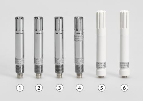
Figure 1 |
HMP60 and HMP110 Series Probes |
||
|
|
|
|
No. |
Model |
|
Description |
1 |
HMP60 |
|
IP65 rated stainless steel probe with INTERCAP® |
|
|
|
sensor. Rugged probe for demanding applications. |
2 |
HMP110 |
|
IP65 rated stainless steel probe with HUMICAP® 180R |
|
|
|
sensor. Rugged probe with higher accuracy for |
|
|
|
demanding applications. |
3 |
HMP110T |
IP65 rated stainless steel probe with temperature |
|
|
|
|
sensor only. Has the same temperature measurement |
|
|
|
performance as HMP110. |
4 |
HMP110REF |
IP65 rated stainless steel probe. Does not measure; |
|
|
|
|
instead, outputs constant humidity and temperature |
|
|
|
readings on serial line. Useful for validating installations |
|
|
|
of HMT120 and HMT130 transmitters, for example. Has |
|
|
|
no analog outputs. |
5 |
HMP63 |
|
IP54 rated probe with PC/ABS plastic housing and |
|
|
|
INTERCAP® sensor. Lightweight probe with faster |
|
|
|
thermal response time. Not for permanent outdoor use. |
6 |
HMP113 |
|
IP54 rated probe with PC/ABS plastic housing and |
|
|
|
HUMICAP® 180R sensor. Lightweight probe with |
|
|
|
higher accuracy and faster thermal response time. |
|
|
|
Not for permanent outdoor use. |
|
|
|
Used with the Vaisala HM40 hand-held meter (requires |
|
|
|
special software configuration). |
12 __________________________________________________________________ M211060EN-E
Chapter 2 __________________________________________________________ Product Overview
Basic Features and Options
-HMP60, HMP63, HMP110 and HMP113 analog output mode: two analog output channels, selectable from 0 ... 1 V / 0 ... 2.5 V / 0 ... 5 V / 1 ... 5 V.
-HMP110T analog output mode: single analog output channel (CH1), selectable from 0 ... 1 V / 0 ... 2.5 V / 0 ... 5 V / 1 ... 5 V.
-RS-485 output mode.
-Small size.
-Low power consumption.
-IP65 stainless steel body on HMP60 and HMP110 models.
-IP54 lightweight plastic body on HMP63 and HMP113 models.
-Options and accessories:
-Several filter options; see section Filter Options on page 14.
-Probe mounting clamp.
-Probe mounting flange.
-Duct installation kit for HMP60, HMP110 and HMP110T.
-One channel loop power converter 4 ... 20 mA (separate module, compatible with humidity accuracy only).
-Shielded 0.3 m and 3.0 m connection cables with threaded connector for probe connection, open end wires on the other end.
-Plastic M12 installation nuts for HMP60, HMP110 and HMP110T.
-Plastic locking bushing for HMP63 and HMP113 (for use with Vaisala products, for example HM40 hand-held meter).
VAISALA _______________________________________________________________________ 13
User's Guide ______________________________________________________________________
Filter Options
For order codes, see section Options and Accessories on page 68.
|
|
|
1001-008 |
|
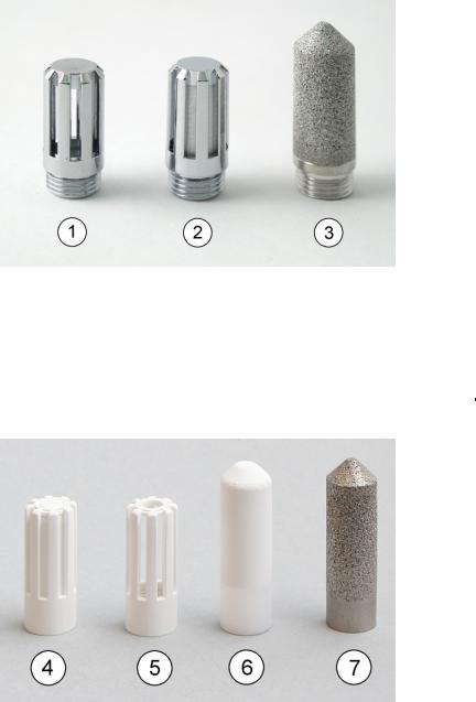
Figure 2 |
Filters for HMP60, HMP110, and HMP110T |
|||
|
|
|
|
|
No. |
Filter |
|
Diameter |
Pore Size |
1 |
Plastic grid filter (fastest response time) |
12 mm |
- |
|
2 |
Membrane filter |
12 mm |
0.2 µm |
|
3 |
Stainless steel sintered filter |
12 mm |
38 µm |
|
|
|
|
1210-010 |
|
Figure 3 |
Filters for HMP63 and HMP113 |
|
||
|
|
|
|
|
No. |
Filter |
|
Diameter |
Pore Size |
4 |
Plastic membrane filter |
12 mm |
0.2 µm |
|
5 |
Plastic grid filter for (portable use only, |
12 mm |
- |
|
|
fastest response time) |
|
|
|
6 |
Porous PTFE filter |
12 mm |
8 µm |
|
7 |
Stainless steel sintered filter |
12 mm |
38 µm |
|
14 __________________________________________________________________ M211060EN-E
Chapter 2 __________________________________________________________ Product Overview
Installation Accessories (Optional)
For order codes, see section Options and Accessories on page 68.
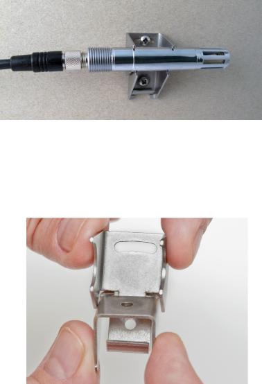
Probe Mounting Clamp
The optional mounting clamp makes it easy to install the probe on the wall of the measurement environment. The probe can be detached for calibration simply by loosening the lower screw.
1001-138
Figure 4 Probe Mounting Clamp in Use
The probe mounting clamp is delivered in two parts that must be connected when it is used:
1.Align the slots on the clamp parts as shown in Figure 5 below.
1209-001
Figure 5 Aligning Mounting Clamp Slots
VAISALA _______________________________________________________________________ 15
User's Guide ______________________________________________________________________
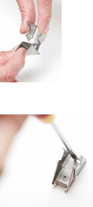
2.Slide the lower clamp part over to the bottom end of the upper part as shown in Figure 6 below.
1209-002
Figure 6 Sliding the Lower Clamp Part
3.Place the clamp to the intended location and secure the upper clamp part with a screw. See Figure 7 below.
1209-003
Figure 7 Securing the Upper Clamp Part
4.Place the probe in the clamp.
5.Tighten the lower clamp part with a screw.
16 __________________________________________________________________ M211060EN-E
Chapter 2 __________________________________________________________ Product Overview
Probe Mounting Flange
The probe mounting flange is a silicone flange that can be used to hold the probe in a through-wall installation. The flange is a general purpose mounting accessory for Ø 12mm probes, and comes with a sealing plug for coaxial cables that is not needed when the flange is used with HMP60 and HMP110 series probes.
0911-109
Figure 8 Probe Mounting Flange
Plastic Locking Bushing for HMP63 and HMP113
HMP63 and HMP113 can be connected to compatible Vaisala instruments using a plastic locking bushing that is placed over the probe. The bushing has a M15x1 thread. It is compatible with the HMT120 and HMT130 transmitters, and the HM40 hand-held meter.
1210-029
Figure 9 HMP113 with Plastic Locking Bushing
VAISALA _______________________________________________________________________ 17
User's Guide ______________________________________________________________________
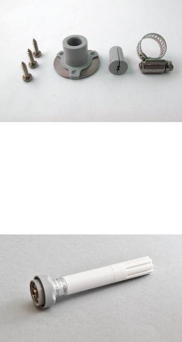
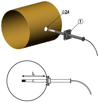
Duct Installation Kit for HMP60, HMP110 and HMP110T
The duct installation kit includes a plastic pipe with a flange (Vaisala order code: 215619). To install the probe with the duct installation kit, drill a hole to the duct wall, assemble the probe to the duct installation kit, slide the probe head through the hole, and attach the flange to the duct wall with four screws. See page 23 for details.
1301-002
Figure 10 Probe Installation with the Duct Installation Kit
The following explanations refer to Figure 10 above: 1 = Tension screw
Distance L can be adjusted and locked in place with the tension screw.
18 __________________________________________________________________ M211060EN-E
Chapter 2 __________________________________________________________ Product Overview
Loop Power Converter
The loop power converter is an open frame module that converts one 0 ... 2.5 VDC voltage output to a 4 ... 20 mA current output. To use the loop power converter module, the probe:
-must be in the analog output mode
-the desired quantity is on channel 1
-channel 1 must be scaled to 0 ... 2.5 V
Wiring instructions are provided in section Wiring with the Loop Power Converter on page 26.
1001-001
Figure 11 Loop Power Converter
VAISALA _______________________________________________________________________ 19
User's Guide ______________________________________________________________________
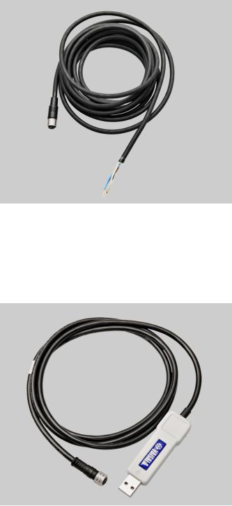
Cables
Connection cables have a straight, threaded female M8 connector on one end and open wires on the other end. Also other compatible M8 series cables can be used.
1210-063
Figure 12 Cable with Threaded Connector
The USB Serial Interface Cable has a straight, threaded female M8 connector on one end, and a USB Type A male plug on the other. The USB cable is intended for maintenance purposes only, not for permanent installation.
1210-062
Figure 13 USB Serial Interface Cable
20 __________________________________________________________________ M211060EN-E
Loading...