

Page 1
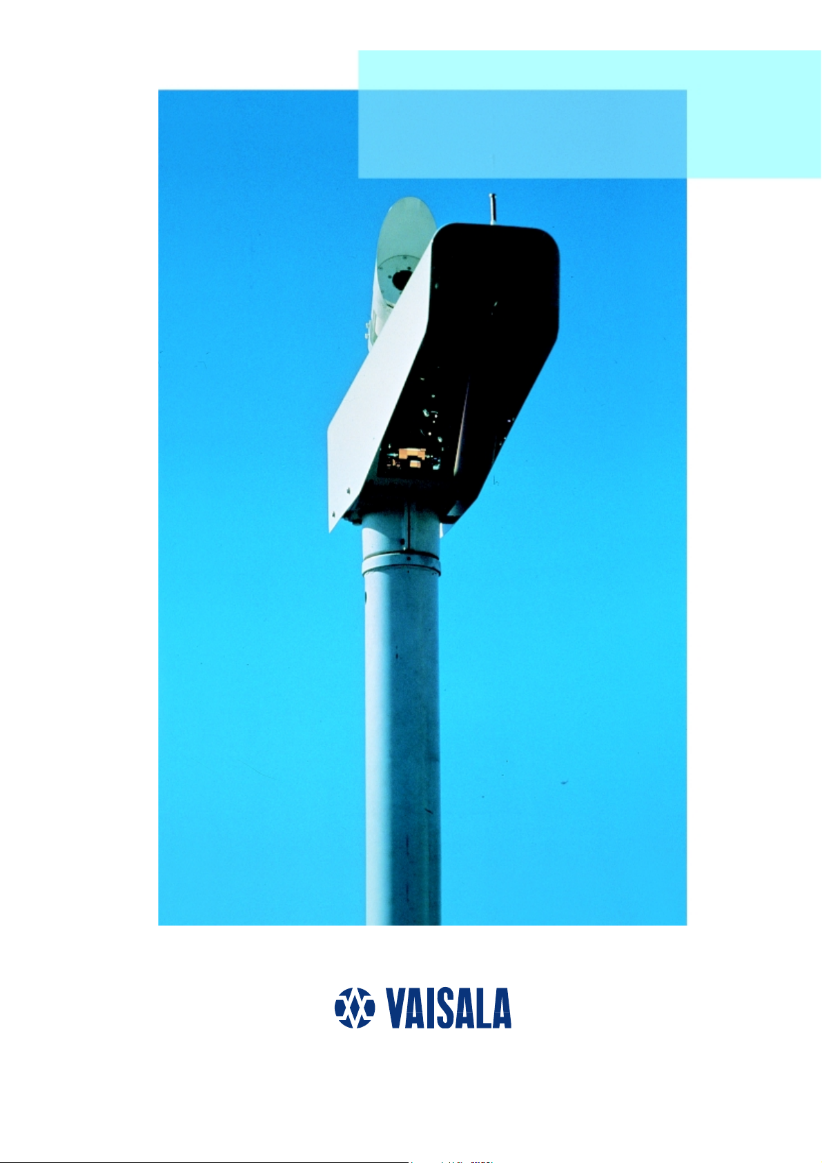
MITRAS Transmissometer
Page 2

Reliable RVR with
MITRAS Transmissometer
Accurate RVR measurement reduces airport downtime and improves safety and reliability of
operations.
The MITRAS Transmissometer system provides You
with correct visibility data without breaks.
Vaisala’s MITRAS is a wellproven solution to Runway
Visual Range assessment. The
system has been in operational
use since 1986 and has demonstrated excellent performance in
international intercomparisons.
MITRAS provides many operational and reliability benefits:
• Conformance to all ICAO and
WMO requirements for RVR and
Meteorological Optical Range
(MOR)
• Fully automatic operation with
excellent accuracy and stability
• Unique contamination detection and compensation
• Double baseline for CAT IIIB
by means of two different beams
from one transmitter
• Extensive built-in monitoring
to verify performance and to
generate warnings before
failures actually occur
• Verified operation in all
weather conditions
SYSTEM STRUCTURE
The standard MITRAS Transmissometer consists of a light
transmitter and a light receiver
installed at a suitable distance
from each other. MITRAS measures transmission of white light
over the baseline path and converts the measurement value to
the corresponding MOR value.
The transmittance measurement
resolution of MITRAS is better
than 0.1 % and the measurement
accuracy is better than 1 %.
A single baseline MITRAS can be
easily and economically upgraded to a double baseline
system when extended measurement range is needed for CAT
IIIB applications. The two baselines are realized by adding an
individual lens system in the
transmitter unit and a second
receiver unit. Excellent accuracy
is guaranteed because the two
separate light beams from the
single transmitter unit do not
interfere with each other.
Vaisala’s LM11 Background
Luminance Meter can be connected to a MITRAS transmitter
unit. The luminance sensor is
interfaced to the MITRAS processor unit and it shares the
same communication line with
the transmissometer.
MITRAS communicates the
measurement results to a host
system via a modem line. RVR
calculations are carried out by a
dedicated RVR computer or an
integrated airport weather
observation system and the
results are sent to various
displays.
COST SAVINGS THROUGH
EASY MAINTENANCE
Contamination of the optical
windows with time is inevitable
and it can have a significant
impact on RVR accuracy. MITRAS measures the window contamination and automatically
compensates for the loss in
measured transmittance. When
The visibility measurement ranges achieved
by single and double baseline MITRAS
systems are shown below. The baseline of
MITRAS can be freely selected between
10 ... 200 m.
Baseline MOR range RVR range*)
35 m 25 ... 1500 m 100 ... 1500 m
50 m 40 ... 2000 m 150 ... 2000 m
75 m 50 ... 3000 m 200 ... 3000 m
100 m 70 ... 5000 m 300 ... 5000 m
200 m 150 ... 10 000 m 500 ... 10 000 m
*) The actual RVR range is dependent on runway lighting.
The values shown are based on usual lighting arrangements.
Baseline MOR range RVR range*)
10 and 75 m 7 ... 3000 m 40 ... 3000 m
10 and 200 m 7 ... 10 000 m 40 ... 10 000 m
(Double baseline is required in CAT IIIB operating category.)
Page 3
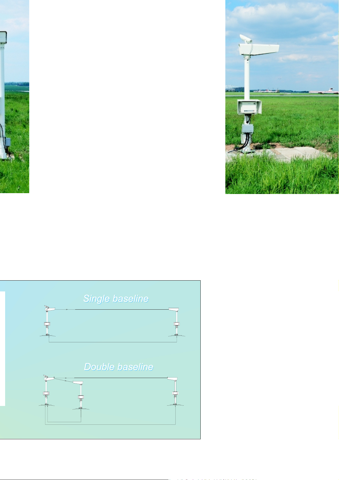
One background luminance meter, mounted
on top of the light transmitter, is sufficient per
runway to measure the background luminance
window contamination exceeds
an acceptable level, a warning is
sent out and the window can be
cleaned. This unique function
extends the cleaning intervals
significantly, while the user is
assured of consistently high data
quality.
Each MITRAS unit continuously
monitors several technical parameters and generates warning
and alarm messages in cases of
fault. The MITRAS status can be
monitored remotely over the
modem line. Automatic monitoring in the transmitter and receiver covers supply voltages,
internal temperatures, optical
performance including correct
calibration/alignment and detected failures. This information can
be interrogated by the service
technician before leaving for the
site. Warnings of lamp ageing
and window contamination are
generated as needed.
The xenon flash lamp’s nominal
lifetime is 8 years at one flash
per second. MITRAS extends the
lifetime by adjusting the flash
rate depending on visibility. An
value needed in visibility calculation.
interval of one second between
flashes is used in low visibility.
The flash interval increases stepwise to 10 seconds when visibility improves to a measured value
above 10 km.
SUPERIOR ACCURACY
In the WMO intercomparison of
visibility measurements, MITRAS
achieved the best results concerning measurement accuracy.
MITRAS measures both the transmitted and the received light
pulse amplitudes. Instead of re-
lying on estimates of projected
light power, every transmitted
pulse is measured. Atmospheric
transmittance is then calculated
as the ratio of received and
transmitted light power on a
single pulse basis. Receiver electronics are gated to receive
only light pulses from the transmitter, and will not accept any
interference light during the
interval.
The wide-bandwidth white light
of the transmitter’s xenon flash
lamp and the photopically
corrected receiver sensitivity
provide an ideal match of the
human eye’s spectral range.
MITRAS beams are optimized.
Interference from other light
sources, such as the sun or the
aircraft lights is minimized by
accurate beam forming. Light
distribution across the beam is
even. Multiple forward scattering
and dispersion in fog is minimized. Simplicity of optical design
and good temperature stability
are key factors of the system’s
exceptional stability.
Temperature of the optics is
maintained constant and above
the ambient to prevent condensed moisture on the optical
surfaces. Control is proportional
to avoid temperature cycling.
Page 4
Technical Information
GENERAL
Measuring range 0 ... 100 % transmittance
Resolution 0.02 % of transmittance
Accuracy (verified by calibrated optical filters) 1 % of FSR
Meets ICAO (Annex 3) recommendations in specific ranges.
Time constant 60 s
Sample interval 1 s
Baseline allocations 10 ... 200 m altered by neutral density filters
Height with standard pedestal (others on request) 2500 mm
Calibration and checks With optical filters &
maintenance terminal command checks
Operating temperature –40 ... +55 °C
Operating humidity 0 ... 10 % RH
Wind speed Construction withstands up to 60 m/s
Power supply 115/130/230/240 VAC
+10 % -15 % of nominal value 45.65 Hz,
Weight 35 kg
Dimensions
Optical head with hood 390(h) × 225(w) × 980(l) mm
Electron. box without rad. shield 310(h) × 400(w) × 190(l) mm
Colour White
Housing Aluminum, weatherproof
Mounting On concrete foundation
LP11 LIGHT TRANSMITTER
Light source Xenon flash bulb
Peak radiated power (adjustable by commands) 40 ... 160 kW
Lamp life 55 000 hours
Spectral output range 300 .... 1100 nm
Microprocessor 8031 with application program
to control all functions, calculations,
communications and built-in test facilities
Power consumption 250 W/300 W with LM11
MTBF (MIL-STD-217E) > 13 700 hours
RVR computer interface Modem CCITT V.21
Dedicated line to RVR computer
Without modem: RS-232C interface
Maintenance terminal interface RS-232C, 300 baud
Output message Visibility, transmittance values,
luminance data (if connected),
Options Double baseline optics (LPO11)
LM11 Background Luminance Meter
single phase
status data in ASCII
LR11 LIGHT RECEIVER
Reception angle 9 mrad
Immunity to external light 75 000 W halogen lamp
30 m far (cont. light) has no influence
Spectral response range 300 ... 700 nm
Peak wavelength 550 nm
Microprocessor 8031 with application program
to control all functions, calculations,
communications and built-in test facilities
Power consumption 250 W
Maintenance terminal interface RS-232C, 300 baud
MTBF (MIL-STD-217E) 22 100 hours
LM11 BACKGROUND LUMINANCE METER
Measuring range 4 ... 30 000 cd/m
Accuracy 10 %
Spectral response range 300 ... 700 nm
Peak wavelength 550 nm
Field of view 5 degrees
MTBF (MIL-STD-217E) 183 000 hours
Connection To any LP11 Light Transmitter
Mounting On top of LP11 by a screw
2
Head Office:
VAISALA Oy
PL 26, FIN-00421 Helsinki
FINLAND
Phone (int.): (+358 0) 894 91
Telefax: (+358 0) 894 9227
Telex: 122832 vsala fi
VAISALA GmbH
Postfach 540267
D-22502 Hamburg
DEUTSCHLAND
Phone (nat.): (040) 858 027
Telefax: (040) 850 8444
VAISALA (UK) Ltd
Cambridge Science Park
Milton Road
Cambridge CB4 4GH
UNITED KINGDOM
Phone (nat.): (01223) 420 112
Telefax: (01223) 420 988
VAISALA TMI Ltd
Vaisala House
349 Bristol Road
Birmingham B5 7SW
UNITED KINGDOM
Phone (nat.): (0121) 683 1200
Telefax: (0121) 683 1299
VAISALA SA
3, Parc Ariane
Saint-Quentin-En-Yvelines
F-78284 Guyancourt Cedex
FRANCE
Phone (nat.): (1) 3057 2728
Telefax: (1) 3096 0858
VAISALA Inc.
100 Commerce Way
Woburn, MA 01801 - 1068
USA
Phone (nat.): (617) 933 4500
Telefax: (617) 933 8029
VAISALA KK
42 Kagurazaka 6-Chome
Shinjuku-Ku,
Tokyo 162
JAPAN
Phone (nat.): (03) 3266 9611
Telefax: (03) 3266 9610
VAISALA Pty. Ltd.
A.C.N. 006 500 616
80 Dodds Street
South Melbourne, VIC 3205
AUSTRALIA
Phone (nat.): (3) 9696 5699
Telefax: (3) 9696 5776
VAISALA Beijing
Representative Office
Room 518, 520
Wangfujing Grand Hotel
No. 57 Wangfujing Street
Beijing 100006
PEOPLE'S REPUBLIC OF CHINA
Phone (nat.): (10) 522 4050
Telefax: (10) 522 4051
Ref. A591en 1995-11
 Loading...