


 Loading...
Portal TI Installation Manual
Unitec
443-561-1200 • www.StartwithUnitec.com

P O R T A L T I
PORTAL TI INSTALLATION MANUAL
Revision C
This manual provides comprehensive installation procedures for the Portal TI. It includes the process of site planning, site preparation, the mechanical installation of the Portal TI and the electrical wiring of the unit.
If further assistance is needed, please contact the distributor from which the Portal TI was purchased.
When calling for assistance, you must have the following information available:
Portal TI Serial Number:
Distributor Name:
D E C L A R A T I O N O F C O M P L I A N C E
This equipment has been tested and found to comply with the limits for a Class A digital device, pursuant to Part 15 of the FCC Rules. These limits are designed to provide reasonable protection against harmful interference when the equipment is operated in a commercial environment. This equipment generates, uses, and can radiate radio frequency energy and, if not installed and used in accordance with the instruction manual, may cause harmful interference to radio communications. Operation of this equipment in a residential area is likely to cause harmful interference in which case the user will be required to correct the interference at his own expense.
C O P Y R I G H T
© 2012 Unitec, Incorporated. All rights reserved. No part of this book, including text, screen examples, diagrams, or icons, may be reproduced or transmitted in any form, by any means (electronic, photocopying, recording, or otherwise) without prior written permission of Unitec, Incorporated.
T R A D E M A R K S
Portal TI, Unitec, and the Unitec Logo are trademarks, service marks, or registered trademarks of Unitec, Incorporated.
All other products, services, and company names are trademarks or registered trademarks of their respective owners.
Portal Installation Manual Rev C
Document #: PTL1001

P O R T A L T I
Table of Contents
1 Site Planning and Preparation ...................................................................................................... |
1 |
|||
|
1.1 |
General .................................................................................................................................. |
1 |
|
|
1.2 |
Mounting Options................................................................................................................... |
1 |
|
|
1.3 |
Positioning the Portal............................................................................................................. |
1 |
|
|
|
1.3.1 |
In-Bay Applications ...................................................................................................................... |
1 |
|
|
1.3.2 |
Express Wash Applications.......................................................................................................... |
3 |
|
1.4 |
Electrical Preparation............................................................................................................. |
4 |
|
|
|
1.4.1 |
Conduit Installation....................................................................................................................... |
4 |
|
|
1.4.2 |
Power Requirements.................................................................................................................... |
6 |
|
|
1.4.3 |
Site Wiring Requirements ............................................................................................................ |
6 |
2 |
Mechanical Installation .................................................................................................................. |
7 |
||
|
2.1 |
Hardware Required................................................................................................................ |
7 |
|
|
2.2 |
Recommended Tools............................................................................................................. |
7 |
|
|
|
2.2.1 |
Mechanical Installation Tools ....................................................................................................... |
7 |
|
2.3 |
Base Installation .................................................................................................................... |
8 |
|
|
2.4 |
Brick-In Installation ................................................................................................................ |
9 |
|
|
|
2.4.1 |
Brick-in Mounting Options ............................................................................................................ |
9 |
|
|
2.4.2 |
Positioning the Portal ................................................................................................................. |
10 |
|
|
2.4.3 |
Brick-in Guidelines ..................................................................................................................... |
13 |
3 |
Electrical Installation.................................................................................................................... |
17 |
||
|
3.1 |
Hardware Required.............................................................................................................. |
17 |
|
|
3.2 |
Recommended Tools........................................................................................................... |
17 |
|
|
3.3 |
General ................................................................................................................................ |
17 |
|
|
3.4 |
Connecting Power ............................................................................................................... |
18 |
|
|
3.5 |
Network Connection ............................................................................................................ |
20 |
|
|
3.6 |
Telephone Cable ................................................................................................................. |
21 |
|
|
3.7 |
Wash Control Wiring............................................................................................................ |
22 |
|
|
|
3.7.1 |
Overview .................................................................................................................................... |
22 |
|
|
3.7.2 Wiring the Wash Relay Interface................................................................................................ |
23 |
|
|
|
3.7.3 Wiring the Wash-In-Use Interface .............................................................................................. |
25 |
|
|
3.8 |
Intercom Systems................................................................................................................ |
27 |
|
|
|
3.8.1 |
Overview .................................................................................................................................... |
27 |
|
|
3.8.2 |
Intercom Connections ................................................................................................................ |
27 |
|
|
3.8.3 |
Intercom Adjustments ................................................................................................................ |
27 |
|
|
3.8.4 |
Connection Overview................................................................................................................. |
28 |
|
|
|
||
|
Portal Installation Manual Rev C |
i |
||
|
Document #: PTL1001 |
|
||

|
|
P O R T A L |
T I |
3.9 Camera Connection............................................................................................................. |
30 |
||
3.10 |
Gate Wiring....................................................................................................................... |
30 |
|
3.11 |
Connecting the Reach Free ID Option.............................................................................. |
30 |
|
4 System Test................................................................................................................................... |
31 |
||
Appendix A. Dimensional Schematic of the Portal TI.................................................................. |
33 |
||
Appendix B. |
IPTran Installation...................................................................................................... |
35 |
|
Appendix C. |
Portal Networking...................................................................................................... |
38 |
|
Appendix D. Installing a Print Server ............................................................................................ |
44 |
||
Appendix F. Installation of the External POS .............................................................................. |
46 |
||
Index of Figures |
|
||
Figure 1. |
Portal Installation at the Wash Entrance................................................................. |
2 |
|
Figure 2. |
Frame Location for Curb Mount.............................................................................. |
2 |
|
Figure 3. |
Express Exterior Island........................................................................................... |
3 |
|
Figure 4. |
Conduit Runs.......................................................................................................... |
4 |
|
Figure 5. |
Portal Base Dimensions ......................................................................................... |
5 |
|
Figure 6. |
Base Installed in Concrete Pad .............................................................................. |
8 |
|
Figure 7. |
Bricked-In Mounting Options ................................................................................ |
10 |
|
Figure 8. |
Positioning the Adaptor Plate ............................................................................... |
11 |
|
Figure 9. |
Door Positioning Options ...................................................................................... |
12 |
|
Figure 10. Portal Mounting for Bricked-In Installation ......................................................... |
13 |
||
Figure 11. Portal Brick-In with Adaptor Plate ...................................................................... |
14 |
||
Figure 12. Portal Brick-In with Adaptor Plate on Base Frame ............................................ |
15 |
||
Figure 13. |
|
Portal Interior ..................................................................................................... |
18 |
Figure 14. Inside the AC Connector.................................................................................... |
19 |
||
Figure 15. |
|
Line - Neutral - Ground Connections ................................................................. |
19 |
Figure 16. Network Port Location ....................................................................................... |
20 |
||
Figure 17. 2-Port Telephone Line Splitter ........................................................................... |
21 |
||
Figure 18. Telephone Line Connection (for Data Modem)................................................... |
22 |
||
Figure 19. Wash I/O Board Connectors.............................................................................. |
24 |
||
Figure 20. 10-Pin Phoenix Connector................................................................................. |
24 |
||
Figure 21. 6-Pin Phoenix Connector................................................................................... |
26 |
||
Figure 22. Intercom Component Locations on the Display IO Board.................................. |
28 |
||
Figure 23. Four-Wire Intercom Configuration ..................................................................... |
29 |
||
Figure 24. |
Three-Wire Intercom Configuration .................................................................... |
29 |
|
Figure 25. |
Two-Wire Intercom Configuration ....................................................................... |
29 |
|
Figure 26. BNC Male Plug for Camera Connection ............................................................. |
30 |
||
Portal Installation Manual Rev C |
ii |
Document #: PTL1001 |
|

P O R T A L T I
1 Site Planning and Preparation
1.1 General
This chapter provides guidelines for planning the Portal installation and preparing the site. Site preparation includes:
•Determining how and where the Portal will be mounted
•Installing conduit runs and required wiring
|
These instructions serve as general guidelines only. If your wash manufacturer’s |
|
installation requirements differ from these guidelines, always meet the wash |
Note: |
manufacturer’s requirements first. |
|
|
|
Requirements specified in local electrical and building codes must be followed and |
|
shall take precedence over the guidelines provided within this document. |
|
|
1.2 Mounting Options
Unitec offers a mounting base for the Portal and a “brick-in” kit. The base is available in (2) heights, 35 in. for a standard (grade) mount and 29 in. for curb mounting. The base consists of a tubular steel frame with a plastic cover. The frame is designed to be embedded in a concrete pad and as such should be installed when concrete is poured at the site. In cases where the concrete is already in place, it’s recommended that holes be drilled into the concrete to secure the legs of the base frame. Refer to section 2.3 for base installation instructions.
The brick-in option includes an adaptor plate that’s designed to provide the proper air circulation required for the heat exchanger air intake and exhaust. The adaptor plate can be attached directly to the brick structure or to the top of a curb height base frame. Refer to section 2.4 for instructions on use of the brick-in adapter plate.
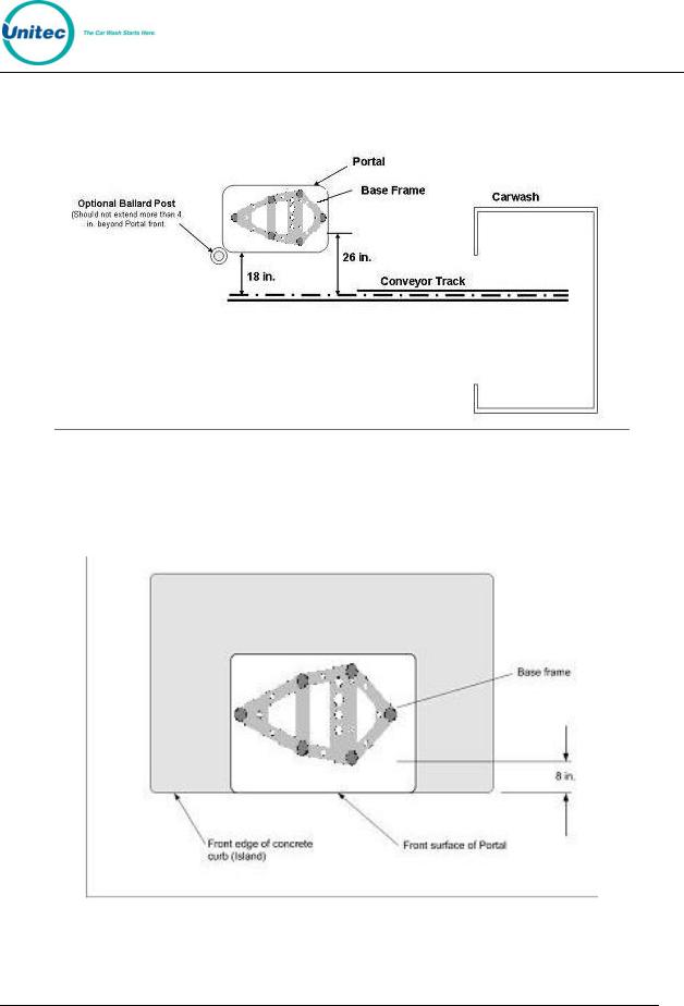
1.3 Positioning the Portal
1.3.1In-Bay Applications
For in-bay automatics and other applications where the Portal is installed at the wash entrance, it should be placed 10’-14’ from the wash to ensure the proper timing and flow of customers. In applications where the Portal is installed adjacent to a conveyor, it should be located 18“ from the centerline of the conveyor track. To
Portal Installation Manual Rev C |
1 |
Document #: PTL1001 |
|
P O R T A L T I
achieve this dimension, the Portal base frame should be located 26 in. from the conveyor centerline as shown in Figure 1.
Figure 1. Portal Installation at the Wash Entrance
For curb mount applications, the front surface of the Portal should be even with the edge of the curb. To achieve this dimension, the base frame should be installed so its leading edge is 8 in. from the edge of the curb as shown in Figure 2.
Figure 2. Frame Location for Curb Mount
Portal Installation Manual Rev C |
2 |
Document #: PTL1001 |
|

P O R T A L T I
1.3.2Express Wash Applications
Express Exterior sites should be designed to provide 9 ft. wide traffic lanes at the Portals. The traffic control (or barrier) gate should be located approximately 10 ft. from
the center of the Portal and an underground vehicle detection loop is required under the gate arm. In some cases, it may be desirable to install a 2nd loop between the gate and tunnel entrance (referred to as the merge loop) to properly manage the vehicle queue.
If the Unitec ReachFree ID (RFID) option is included, the RF Antenna should be located adjacent to the Portal. Figure 3 provides guidelines for the design of an Express lane with the Portal, gate and RFID (antenna) option. Refer to the installation instructions provided with the gate and RFID option for guidance in installing these devices.
Figure 3. Express Exterior Island
Portal Installation Manual Rev C |
3 |
Document #: PTL1001 |
|

P O R T A L T I
1.4 Electrical Preparation
1.4.1Conduit Installation
A typical installation will require 3 conduit runs for, power, data and wash control lines. DO NOT run data wires in the AC Power or Wash Control conduits. Additional conduit runs may be needed when a gate or the Portal RFID option are to be used. Conduit size should be at least ¾ in, a larger conduit may be required depending on the quantity and gauge of wires to be installed. Refer to local and national electrical codes to select the proper conduit type and size. Figure 4 provides guidelines for conduit planning.
Figure 4. Conduit Runs
To ensure the conduit sections will be located within the Portal base and not interfere with the base frame, they should be routed so the stubs can be contained within the 4 inch square areas shown in the Figure 5.
Portal Installation Manual Rev C |
4 |
Document #: PTL1001 |
|

P O R T A L T I
Figure 5. Portal Base Dimensions
The Portal base frame is a welded tubular structure that has the same plate on the top and bottom. Its designed so that wires and/or conduit can be routed into the Portal through the round conduit holes on the top. However, it will be far easier to bring the conduit stubs into the frame through the large rectangular cut outs on the bottom plate. You can then attach flex conduit between the stubs and conduit holes on the top panel or just run the wires from the stubs up through these holes.
Portal Installation Manual Rev C |
5 |
Document #: PTL1001 |
|

P O R T A L T I
1.4.2Power Requirements
The Portal requires 120 VAC, 8 Amps service. In applications where barrier gates are to be used, each gate requires 120 VAC, 5 Amps service. The Portal and Gate must be powered from separate circuits.
Ensure the protective earth ground wires do not carry any motor return current. Only Note: the neutral wire should carry return current. Follow local electrical code when wiring
the Portal TI.
1.4.3Site Wiring Requirements
Wiring requirements will vary by site depending on the type of wash equipment and the Portal configuration. The following table shows site wiring, which may be needed. As wires are pulled through conduit, ensure there is at least 6 ft. of wire extending from the end of the conduit stub.
Circuit Description |
Wire Qty |
Wire Requirements |
||
Portal Power (115-120 VAC, 8 Amps). |
3 |
16 AWG minimum, black/white/green |
||
Gate Power (115-120 VAC, 5 Amps). |
3 |
16 AWG minimum, black/white/green |
||
Network connection (to router) |
1 |
Cat 5 communications cable, 295 ft max length |
||
Wash Signaling (required if the Portal will be |
Varies |
Refer to wash equipment manufacturer’s |
||
connected to the wash controller) |
instructions |
|||
|
||||
Phone Line |
1 |
2 Pair / 4 Conductor Telephone Cable |
||
(required for dial-up credit option) |
||||
|
|
|
||
Intercom |
4 |
22 AWG minimum |
||
(Required to interface with site intercom) |
||||
|
|
|
||
Camera |
1 |
Type RG59/U coaxial cable |
||
(Required for Portal camera option) |
||||
|
|
|
||
Gate Control – from gate controller to Portal |
4 |
18 AWG minimum |
||
(Required if gate controller is used) |
||||
|
|
|
||
Gate Control - from gate controller to gate |
3 |
18 AWG minimum |
||
(Required if gate controller is used) |
||||
|
|
|
||
Gate Control – from Portal to Gate |
4 |
18 AWG minimum |
||
(Required if gate is used without gate controller) |
||||
|
|
|
||
RFID Option |
1 |
Cable is supplied with RFID kit |
||
(from RFID Antenna to Portal) |
||||
|
|
|
||
|
|
|
|
|
Portal Installation Manual Rev C |
|
6 |
|
|
Document #: PTL1001 |
|
|
|
|
P O R T A L T I
2 Mechanical Installation
2.1 Hardware Required
Prior to beginning the installation, take the time to verify that all the following required parts are present and accounted for.
Items supplied with the Portal:
•Allen Wrench For Door
•Key set for door
•Key set for vault door
•IEC-320-C14 Female AC Power Connector
Items supplied with the Base:
•(3) ½: Hex Nuts
•(3) ½” Flat Washers
•(3) ½” Lock Washers
Items supplied with the Brick-in Option:
•Adapter Plate
•(4) J-Bolts and nuts (for securing the adapter plate)
•(3) ½:” x 1” Hex Bolts
•(3) ½” Flat Washers
•(3) ½” Lock Washers
2.2Recommended Tools
2.2.1Mechanical Installation Tools
The following tools are recommended for the typical mechanical installation of this Portal TI unit and base:
•¾” deep well socket and socket wrench
•Open end 9/16” wrench
•Small, thin blade, flat-tip screwdriver
•Hammer
•Dual-plane Level
•50’ foot tape measure
Portal Installation Manual Rev C |
7 |
Document #: PTL1001 |
|

P O R T A L T I
The following items are required only when installing the Portal TI into an existing concrete slab:
•Hammer drill
•2.5” Concrete hammer drill bit
2.3Base Installation
Note: |
Pull all wires through conduits before mounting the base. See Electrical Planning for |
|
wiring requirements. |
||
|
||
|
|
When installing the Portal TI frame, it is recommended that the concrete pad be undercut, as illustrated in the figure below. This type of installation provides greater security. The undercut pad size should have the following dimensions:
Pad Dimension Requirements
|
Minimum |
Recommended |
Surface Width |
18” |
48” |
Undercut Depth |
8” |
24” |
Figure 6. Base Installed in Concrete Pad
To ensure the base is installed at the proper height, the lower cross braces should be flush with the concrete surface (the braces are located 6 in. from the bottom of the frame). Ensure the base frame is level and place the plastic base cover over the frame after the concrete has set.
Portal Installation Manual Rev C |
8 |
Document #: PTL1001 |
|

P O R T A L T I
When installing the frame in pre-existing concrete, set the frame in the desired location and mark the location of each leg of the frame. Drill 2 ½ in. diameter by 8 in. deep (minimum) holes in the concrete for the frame legs. Fill the holes with concrete anchoring cement (such as Quickrete #1245-20) and insert the base legs. Ensure the frame is level and place the plastic base cover over the frame after the anchoring cement has set.
For added security, the base can be filled with concrete. Before doing so however, the Note: electrical conduits should be extended to the top of the frame. A rope (or similar material) should be tied around the plastic cover to prevent it from expanding as
concrete is poured.
Before setting the Portal in place, ensure the field-installed wires are routed to a point where they can be accessed and pulled through the wiring holes on the bottom of the Portal. Carefully set the Portal on top of the base so the (3) studs of the base pass through the mounting holes on the bottom of the Portal. Secure the Portal to the studs with the flat washer, lock washer and hex nut (in that order) supplied with the base. Pull the wires up through the cable entrance ports on the bottom of the Portal enclosure.
2.4 Brick-In Installation
2.4.1Brick-in Mounting Options
There are (2) options for bricked-in mounting:
•Build the brick enclosure, fill it with concrete, sink the Adaptor Plate with Mounting Bolts into the wet concrete, let the concrete cure, mount the Portal TI unit, and then finish bricking in the unit.
•Install the Curb-Height Steel Frame, attach the Adaptor Plate, build the brick enclosure around the frame, mount the Portal TI unit, and finish bricking in the unit. For added security, you can fill the brick enclosure with concrete prior to mounting the Portal TI unit.
Portal Installation Manual Rev C |
9 |
Document #: PTL1001 |
|

P O R T A L T I
Figure 7. Bricked-In Mounting Options
2.4.2Positioning the Portal
The adapter plate should be located so its front edge is recessed 4.50” from the front face of the brick structure (as shown in Figure 8). The adapter plate has (2) sets of mounting holes. One set is used to install the Portal so its front door will be flush with the brick. The other set is used to recess the door within the brick. These (2) mounting options and hole patterns are illustrated in Figure 9 and Figure 10..
Electrical conduits should be extended to the adapter plate and positioned so wiring can be routed through the rectangular opening in the plate.
Portal Installation Manual Rev C |
10 |
Document #: PTL1001 |
|

P O R T A L T I
Figure 8. Positioning the Adaptor Plate
Portal Installation Manual Rev C |
11 |
Document #: PTL1001 |
|
Loading...