


Washer-Extractor
Pocket Hardmount
UniLinc Control
Refer to Page 9 for Model Identification
PHM14
PHM1423C
Keep These Instructions for Future Reference.
(If this machine changes ownership, this manual must accompany machine.)
|
|
|
www.comlaundry.com |
Part No. F8434101R1 |
|
|
|
||
|
|
|
April 2012 |
<![endif]>Programming
Table of
Contents
Safety Information.............................................................................. |
5 |
Explanation of Safety Messages........................................................... |
5 |
Important Safety Instructions ............................................................... |
5 |
Safety Decals ........................................................................................ |
7 |
Operator Safety..................................................................................... |
8 |
Introduction......................................................................................... |
9 |
Model Identification ............................................................................. |
9 |
Nameplate Location.............................................................................. |
10 |
Replacement Parts ................................................................................ |
10 |
Customer Service.................................................................................. |
10 |
Preliminary Information.................................................................... |
11 |
About the Control ................................................................................. |
11 |
Power Failure Recovery................................................................... |
11 |
IR Communications ......................................................................... |
11 |
Network Communications ............................................................... |
11 |
Audit Information ........................................................................... |
11 |
IR Communications Menu............................................................... |
12 |
IR Communications Error Menu ..................................................... |
12 |
Restore to Factory Defaults ............................................................ |
12 |
Entering Program Mode................................................................... |
13 |
UniLinc Identification ........................................................................ |
14 |
Operational Keypad .............................................................................. |
14 |
Operation Modes .................................................................................. |
15 |
General Modes of Operation............................................................ |
15 |
Power-up Mode................................................................................ |
15 |
Idle Mode ......................................................................................... |
15 |
Door Locking Mode......................................................................... |
15 |
Run Mode......................................................................................... |
15 |
Stop Mode........................................................................................ |
15 |
Door Unlocking Mode ..................................................................... |
15 |
Error Mode....................................................................................... |
15 |
Delayed Start Countdown Mode...................................................... |
15 |
Communication Mode ..................................................................... |
15 |
Entering Diagnostic Mode From Idle Mode.................................... |
15 |
Machine Cycle Definition and Operation......................................... |
16 |
Machine Cycle Operation ..................................................................... |
16 |
Delayed Start Feature ........................................................................... |
16 |
Cycle Menu........................................................................................... |
16 |
To Start a Cycle ............................................................................... |
17 |
Run Menu ............................................................................................. |
18 |
Contrast/Backlight Menu...................................................................... |
20 |
Close Door Menu.................................................................................. |
20 |
Lubricate Bearings Menu ..................................................................... |
21 |
Run Diagnostic Menu........................................................................... |
21 |
Speed, Temp and Water Level Menu ................................................... |
22 |
Cycle Aborted Retry Menu................................................................... |
22 |
Cycle Aborted Fatal Menu.................................................................... |
23 |
© Copyright 2012, Alliance Laundry Systems LLC
All rights reserved. No part of the contents of this book may be reproduced or transmitted in any form or by any means without the expressed written consent of the publisher.
F8434101 |
© Copyright, Alliance Laundry Systems LLC – DO NOT COPY or TRANSMIT |
1 |
Error Menu............................................................................................ |
23 |
Cycle Stopped Menu............................................................................. |
23 |
Delayed Start Menu .............................................................................. |
23 |
Delayed Start Countdown Menu .......................................................... |
24 |
Delayed Start Final Countdown Menu ................................................. |
24 |
Menu Navigation................................................................................. |
25 |
The UniLinc.......................................................................................... |
25 |
Menu Navigation on a Single Screen ................................................... |
25 |
Menu Navigation with Parameters ....................................................... |
25 |
Screen to Screen Navigation using the Arrow Keypads....................... |
25 |
Navigation in String Edit Mode............................................................ |
25 |
Display Screen Maps ............................................................................ |
26 |
System Menu Map Tree................................................................... |
26 |
Run Menu Map Tree........................................................................ |
27 |
Service Menu Map Tree................................................................... |
27 |
Programming UniLinc ....................................................................... |
28 |
System Menu ........................................................................................ |
28 |
Save Changes Menu ............................................................................. |
28 |
Program Menu.................................................................................... |
29 |
Program Menu ...................................................................................... |
29 |
Modify Cycle........................................................................................ |
29 |
Available Characters........................................................................ |
30 |
Cycle, Segment and Step Programming Flow Diagram....................... |
31 |
Step Menu Navigation ..................................................................... |
31 |
Reuse Fill Step Menu....................................................................... |
32 |
Fill Step Menu.................................................................................. |
33 |
Heater Option................................................................................... |
34 |
Supply A and B Step Menu ............................................................ |
34 |
Agitate Step Menu ........................................................................... |
35 |
Cool Down Step Menu..................................................................... |
35 |
Drain Step Menu ............................................................................. |
36 |
Spray Rinse Extract Step Menu ....................................................... |
36 |
Extract Step Menu............................................................................ |
37 |
General Purpose Signals Menu........................................................ |
37 |
End of Segment Audio Signal Step Menu ....................................... |
38 |
Global Setup........................................................................................ |
39 |
Global Setup Menu............................................................................... |
39 |
Language Menu .................................................................................... |
39 |
Date/Time Menu................................................................................... |
39 |
Water Level Menu ................................................................................ |
40 |
Temperature Menu................................................................................ |
40 |
Audio Menu.......................................................................................... |
41 |
Balance Retry Menu ............................................................................. |
41 |
Water Management Menu .................................................................... |
42 |
Alarms Program Menu ......................................................................... |
44 |
Rapid Advance Menu ........................................................................... |
44 |
Shakeout Menu ..................................................................................... |
45 |
2 |
© Copyright, Alliance Laundry Systems LLC – DO NOT COPY or TRANSMIT |
F8434101 |
Banners Menu....................................................................................... |
45 |
Factory Defaults Menu ......................................................................... |
45 |
Water Level Confirmation Menu.......................................................... |
46 |
Water Temperature Confirmation Menu .............................................. |
46 |
Alarms Confirmation Menu.................................................................. |
46 |
Audio Confirmation Menu ................................................................... |
47 |
Reset All Factory Defaults Confirmation Menu................................... |
47 |
Factory Defaults Second Confirmation Menu...................................... |
47 |
Diagnostic ............................................................................................ |
48 |
Diagnostic Menu................................................................................... |
48 |
Drive ID Menu................................................................................. |
48 |
Drive Alarms Menu ......................................................................... |
48 |
Test Menu ............................................................................................. |
48 |
Test Cycle ........................................................................................ |
49 |
Factory Valve Purge Menu................................................................... |
51 |
Inputs Outputs Menu ............................................................................ |
51 |
Water Leak Detection Diagnostic......................................................... |
53 |
Drive Test ............................................................................................. |
53 |
Alarms................................................................................................... |
54 |
Machine Identification.......................................................................... |
55 |
Machine Errors ..................................................................................... |
55 |
Door Lock Error .............................................................................. |
55 |
Door Open Error ............................................................................. |
55 |
Drain Alarm Error ........................................................................... |
55 |
Fill Alarm Error ............................................................................... |
55 |
Frame Balance Switch Error............................................................ |
56 |
Open Temperature Sensor Error ..................................................... |
56 |
Shorted Temperature Sensor Error ................................................. |
56 |
SPI Error .......................................................................................... |
56 |
Unbalance Error ............................................................................... |
56 |
Heat Alarm Error ............................................................................. |
56 |
Water Level Sensor Error ................................................................ |
57 |
IR Communications Error................................................................ |
57 |
Network Communications Error...................................................... |
57 |
Water Leak Detection Error............................................................. |
57 |
Slow Drain Detected During A Machine Cycle Error ..................... |
58 |
Drive SPI Error ................................................................................ |
58 |
DC Bus Error ................................................................................... |
58 |
No Tachometer Error ....................................................................... |
58 |
Locked Rotor Error .......................................................................... |
58 |
Shorted IGBT Error ......................................................................... |
58 |
IPM Overtemperature Error............................................................. |
59 |
Invalid Parameter Set Error ............................................................. |
59 |
Maximum Current Exceeded Error.................................................. |
59 |
Current Sensor Error ........................................................................ |
59 |
Low DC Bus Error ........................................................................... |
59 |
Invalid Command Error ................................................................... |
59 |
Last Drive Error ............................................................................... |
59 |
F8434101 |
© Copyright, Alliance Laundry Systems LLC – DO NOT COPY or TRANSMIT |
3 |
Laundry Management........................................................................ |
60 |
Total Number of Machine Cycle Counters........................................... |
61 |
Total Number of Operating Minutes Counters..................................... |
61 |
Last 10 Machine Cycles Rapid Advanced or Stopped ......................... |
61 |
Maintenance........................................................................................ |
62 |
Service Schedule Menu ........................................................................ |
62 |
Daily Menu (Service)....................................................................... |
62 |
Weekly Menu (Service) ................................................................... |
62 |
Monthly Menu (Service).................................................................. |
63 |
Quarterly Menu (Service) ................................................................ |
63 |
Cycle Charts........................................................................................ |
64 |
4 |
© Copyright, Alliance Laundry Systems LLC – DO NOT COPY or TRANSMIT |
F8434101 |

Safety Information
Explanation of Safety Messages
Precautionary statements (“DANGER,” “WARNING,” and “CAUTION”), followed by specific instructions, are found in this manual and on machine decals. These precautions are intended for the personal safety of the operator, user, servicer, and those maintaining the machine.
DANGER
DANGER indicates the presence of a hazard that will cause severe personal injury, death, or substantial property damage if the danger is ignored.
WARNING
WARNING indicates the presence of a hazard that can cause severe personal injury, death, or substantial property damage if the warning is ignored.
CAUTION
CAUTION indicates the presence of a hazard that will or can cause minor personal injury or property damage if the caution is ignored.
Additional precautionary statements (“IMPORTANT” and “NOTE”) are followed by specific instructions.
IMPORTANT: The word “IMPORTANT” is used to inform the reader of specific procedures where minor machine damage will occur if the procedure is not followed.
NOTE: The word “NOTE” is used to communicate installation, operation, maintenance or servicing information that is important but not hazard related.
Important Safety Instructions
WARNING
To reduce the risk of fire, electric shock, serious injury or death to persons when using your washer, follow these basic precautions:
W023
1.Read all instructions before using the washer.
2.GInstall the washer according the INSTALLATION instructions. Refer to the GROUNDING instructions in the INSTALLATION manual for the proper grounding of the washer. All connections for water, drain, electrical power and grounding must comply with local codes and be made by licensed personnel when required. It is recommended that the machine be installed by qualified technicians.
3.Do not install or store the washer where it will be exposed to water and/or weather.
4.To prevent fire and explosion, keep the area around machine free from flammable and combustible products. Do not add the following substances or textiles containing traces of the following substances to the wash water: gasoline, kerosene, waxes, cooking oils, vegetable oils, machine oils, dry-cleaning solvents, flammable chemicals, thinners, or other flammable or explosive substances. These substances give off vapors that could ignite, explode or cause the fabric to catch fire by itself.
5.Under certain conditions, hydrogen gas may be produced in a hot water system that has not been used for two weeks or more. HYDROGEN GAS IS EXPLOSIVE. If the hot water system has not been used for such a period, before using a washing machine or combination washer-dryer, turn on all hot water faucets and let the water flow from each for several minutes. This will release any accumulated hydrogen gas. The gas is flammable, do not smoke or use an open flame during this time.
6.To reduce the risk of an electric shock or fire, DO NOT use an extension cord or an adapter to connect the washer to the electrical power source.
F8434101 |
© Copyright, Alliance Laundry Systems LLC – DO NOT COPY or TRANSMIT |
5 |
Safety Information
7.Do not allow children to play on or in the washer. Close supervision of children is necessary when the washer is used near children. This appliance is not intended for use by young children or infirm persons without supervision. Young children should be supervised to ensure that they do not play with the appliance. This is a safety rule for all appliances.
8.DO NOT reach and/or climb into the tub or onto the washer, ESPECIALLY if the wash drum is moving. This is an imminently hazardous situation that, if not avoided, will cause severe personal injury or death.
9.Never operate the washer with any guards, panels and/or parts removed or broken. DO NOT bypass any safety devices or tamper with the controls.
10.Use washer only for its intended purpose, washing textiles. Never wash machine parts or automotive parts in the machine. This could result in serious damage to the basket or tub.
11.Use only low-sudsing, no-foaming types of commercial detergent. Be aware that hazardous chemicals may be present. Wear hand and eye protection when adding detergents and chemicals. Always read and follow manufacturer’s instructions on packages of laundry and cleaning aids. Heed all warnings or precautions. To reduce the risk of poisoning or chemical burns, keep them out of the reach of children at all times (preferably in a locked cabinet).
12.Do not use fabric softeners or products to eliminate static unless recommended by the manufacturer of the fabric softener or product.
13.Always follow the fabric care instructions supplied by the textile manufacturer.
14.Loading door MUST BE CLOSED any time the washer is to fill, tumble or spin. DO NOT bypass the loading door switch by permitting the washer to operate with the loading door open. Do not attempt to open the door until the washer has drained and all moving parts have stopped.
15.Be aware that hot water is used to flush the supply dispenser. Avoid opening the dispenser lid while the machine is running.
16.Do not attach anything to the supply dispenser’s nozzles, if applicable. The air gap must be maintained.
17.Do not operate the machine without the water reuse plug or water reuse system in place, if applicable.
18.Be sure water connections have a shut-off valve and that fill hose connections are tight. CLOSE the shut-off valves at the end of each wash day.
19.Keep washer in good condition. Bumping or dropping the washer can damage safety features. If this occurs, have washer checked by a qualified service person.
20.DANGER: Before inspecting or servicing machine, power supply must be turned OFF. The servicer needs to wait for at least 3 minutes after turning the power OFF and needs to check for residual voltage with a voltage meter. The inverter capacitor or EMC filter remains charged with high voltage for some time after powering OFF. This is an imminently hazardous situation that, if not avoided, will cause severe personal injury or death.
21.Do not repair or replace any part of the washer, or attempt any servicing unless specifically recommended in the user-maintenance instructions or in published user-repair instructions that the user understands and has the skills to carry out. ALWAYS disconnect the washer from electrical, power and water supplies before attempting any service.
22.Disconnect the power cord by grasping the plug, not the cord. Replace worn power cords and/or loose plugs. If the supply cord is damaged, it must be replaced by a special cord or assembly available from the service agent.
23.Before the washer is removed from service or discarded, remove the door to the washing compartment.
24.Failure to install, maintain, and/or operate this washer according to the manufacturer’s instructions may result in conditions which can produce bodily injury and/or property damage.
NOTE: The WARNINGS and IMPORTANT SAFETY INSTRUCTIONS appearing in this manual are not meant to cover all possible conditions and situations that may occur. Common sense, caution and care must be exercised when installing, maintaining, or operating the washer.
Any problems or conditions not understood should be reported to the dealer, distributor, service agent or the manufacturer.
6 |
© Copyright, Alliance Laundry Systems LLC – DO NOT COPY or TRANSMIT |
F8434101 |
WARNING
This machine must be installed, adjusted, and serviced by qualified electrical maintenance personnel familiar with the construction and operation of this type of machinery. They must also be familiar with the potential hazards involved. Failure to observe this warning may result in personal injury and/or equipment damage, and may void the warranty.
SW004
CAUTION
Ensure that the machine is installed on a level floor of sufficient strength and that the recommended clearances for inspection and maintenance are provided. Never allow the inspection and maintenance space to be blocked.
SW020
CAUTION
Be careful around the open door, particularly when loading from a level below the door. Impact with door edges can cause personal injury.
SW025
Safety Information
WARNING
Never touch internal or external steam pipes, connections, or components. These surfaces can be extremely hot and will cause severe burns. The steam must be turned off and the pipe, connections, and components allowed to cool before the pipe can be touched.
SW014
Safety Decals
Safety decals appear at crucial locations on the machine. Failure to maintain legible safety decals could result in injury to the operator or service technician.
Use manufacturer-authorized spare parts to avoid safety hazards.
F8434101 |
© Copyright, Alliance Laundry Systems LLC – DO NOT COPY or TRANSMIT |
7 |

Safety Information
Operator Safety
WARNING
NEVER insert hands or objects into basket until it has completely stopped. Doing so could result in serious injury.
SW012
The following maintenance checks must be performed daily:
1.Verify that all warning signs are present and legible, replace as necessary.
2.Check door interlock before starting operation of the machine:
a.Attempt to start the machine with the door open. The machine should not start.
b.Close the door without locking it and start the machine. The machine should not start.
c.Attempt to open the door while a cycle is in progress. The door should not open.
If the door lock and interlock are not functioning properly, disconnect power and call a service technician.
3.Do not attempt to operate the machine if any of the following conditions are present:
a.The door does not remain securely locked during the entire cycle.
b.Excessively high water level is evident.
c.Machine is not connected to a properly grounded circuit.
Do not bypass any safety devices in the machine.
WARNING
Operating the machine with severe out-of- balance loads could result in personal injury and serious equipment damage.
W728
NOTE: All information, illustrations, and specifications contained in this manual are based on the latest product information available at the time of printing. We reserve the right to make changes at any time without notice.
8 |
© Copyright, Alliance Laundry Systems LLC – DO NOT COPY or TRANSMIT |
F8434101 |
Introduction |
|
|
Model Identification |
|
|
Information in this manual is applicable to these |
|
|
models: |
|
|
|
|
|
UWL045T3V |
|
UWN065T4L |
|
|
|
UWL045T4V |
|
UWN065T4M |
|
|
|
UWL065T3V |
|
UWU045T3V |
|
|
|
UWL065T4V |
|
UWU045T4V |
|
|
|
UWN045T3V |
|
UWU065T3L |
|
|
|
UWN045T4V |
|
UWU065T3M |
|
|
|
UWN065T4V |
|
UWU065T3V |
|
|
|
UWN065T3L |
|
UWU065T4L |
|
|
|
UWN065T3M |
|
UWU065T4M |
|
|
|
UWN065T3V |
|
UWU065T4V |
|
|
|
F8434101 |
© Copyright, Alliance Laundry Systems LLC – DO NOT COPY or TRANSMIT |
9 |
Introduction
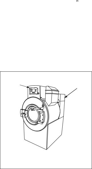
Nameplate Location
The nameplate is located on the back of the machine and is programmed in the UniLinc Control. To access Machine ID through the control:
1.Press and hold  , then
  , then
  keypads at the same time.
2.Press the  keypad until Diagnostic is highlighted.
3.Press the  keypad.
4.Press the  keypad until Machine ID is highlighted.
5.Press the  keypad.
Always provide the machine’s serial number and model number when ordering parts or when seeking technical assistance. Refer to Figure 1.
EXAMPLE OF MACHINE NAMEPLATE LOCATION
1
2
PHM847N
PHM847N
1 In UniLinc Control
2At back of machine
Figure 1
Replacement Parts
If literature or replacement parts are required, contact the source from which the machine was purchased or contact Alliance Laundry Systems LLC at
+1 920) 748-3950 for the name of the nearest authorized parts distributor. A parts manual may be ordered by returning the reply card provided with each machine.
Customer Service
For technical assistance, contact your local distributor or call:
Alliance Laundry Systems
Shepard Street
P.O. Box 990
Ripon, WI 54971-0990
U.S.A.
www.comlaundry.com
Phone: +1 (920) 748-3121
Ripon, Wisconsin
Alliance International
+32 56 41 20 54
Wevelgem, Belgium
10 |
© Copyright, Alliance Laundry Systems LLC – DO NOT COPY or TRANSMIT |
F8434101 |
Preliminary Information
About the Control
The UniLinc control on the machine is an advanced, graphical, programmable computer that lets the owner control most machine features by interacting with the control.
UniLinc allows the owner to program custom cycles, run diagnostic cycles and retrieve audit, error and bearing information.
Machines shipped from the factory have default cycles and wash temperature settings built in. The owner can change the default cycles or any cycle.
IMPORTANT: It is extremely important that the machine has a positive ground and that all mechanical and electrical connections are made before applying power to or operating the machine.
Power Failure Recovery
If a cycle is in progress when the power fails, and if the power outage lasts three or more seconds, the cycle is lost and cannot be resumed when power recovers. If the power outage lasts less than three seconds, the control will resume the cycle when the power recovers.
IR Communications
The control has the ability to communicate with a PDA or PC with an IrDA device running the UniLinc software. Devices such as PDAs and PCs that are IrDA capable (able to transmit information to machine) that have been tested and approved for use with the UniLinc software can be used as a tool for managing the machine.
Network Communications
The control has the ability to communicate through a network. The network link allows the user to program, collect data, and run diagnostics on any machine in the network from a central location.
Audit Information
The control collects and stores audit information, which can be accessed with a PC/PDA or through the network. Refer to the following list for available audit information.
•Total Number of Individual Cycle Counters
•Last 25 Machine Cycles
•Service History
•Machine Errors Audit Data
•Communication Audit Data
•Re-Programming Audit Data
•Power Failures Audit Data
•Average Fill Time Audit Data
•Average Drain Time Audit Data
•Power Failure Audit Data
The PC/PDA or the network can receive audit and program data from the control, and send programming data and diagnostic commands to the control.
Refer to UniLinc PC and PDA Application User Instructions for additional information on using a PC/ PDA.
F8434101 |
© Copyright, Alliance Laundry Systems LLC – DO NOT COPY or TRANSMIT |
11 |
Preliminary Information
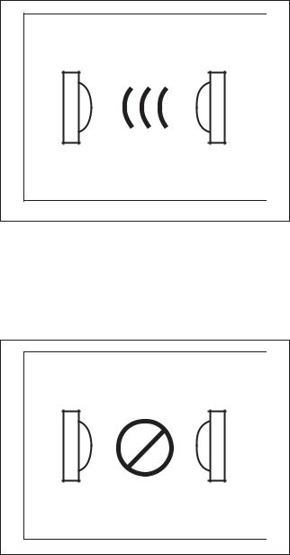
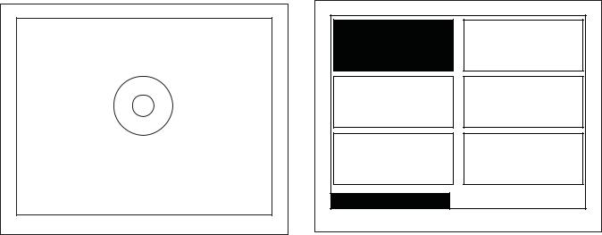
IR Communications Menu
PHM1003R
Figure 2
The IR Communications Menu displays while the control is communicating with a PC/PDA. The control will jump back to the previous page when the communication is complete.
IR Communications Error Menu
Invalid Data |
PHM1004N |
Figure 3
The IR Communications Error Menu displays after the control had an error communicating with a PC/PDA. The control will return to previous page after 3 seconds.
Restore to Factory Defaults
When the user selects Restore All Cycles And Global Settings To Factory-Defaults, the control resets all of the default values. The control also resets Machine Cycles #1 through #41. The control will also reset the following to factory defaults:
Default Machine Settings
Language = English
Maximum Balance Retries = 3
Water Reuse = Disabled
Rapid Advance = Enabled
Water Recirculation = Disabled
External Dispenser Pause = Disabled
Shakeout = 40 seconds
Banner # 1 = Blank
Banner # 2 = Blank
Daylight Saving = Enabled
Water Levels
High = 27
Medium = 15
Low = 3
Water Temperature
Hot = 140 F
Warm = 100 F
Cold = 35 F
Cooldown = 110 F
Temperature Controlled Fill = Disabled
Audio Signal External Signal = Disabled
Keypad Signal (beep) = Enabled
Alarms
Fill = 5 minutes
Drain = 2 minutes
Heat = 1 hour 30 minutes
End of Segment / Cycle Sound = Enabled Low, 5 second duration
Advanced Options for Water Management = Disabled
Water Leak Detection During Machine Cycle =
Disabled
Number of Cycles Between = 0
Day(s) Occuring = none
12 |
© Copyright, Alliance Laundry Systems LLC – DO NOT COPY or TRANSMIT |
F8434101 |
Slow Drain Detection During Machine Cycle =
Disabled
Slow Drain Adjustment = 0 seconds
Auto-Water Leak Detection = Disabled
Number of Cycles Between = 0
Hours Occuring = 0 (12:00 AM)
Days(s) Occuring = none
Manual Programming = Enabled*
Manual Diagnostics = Enabled*
*If manual programming is disabled, programming changes to UniLinc can only be made with an external communication device. Refer to UniLinc PC and
PDA Applications User Instructions.
Refer to Factory Defaults, Menu section for information on Restoring Factory Defaults.
Preliminary Information
Entering Program Mode
1.Press and hold  , then
  , then
  to enter the System Menu. Select Program to enter programming options.
F8434101 |
© Copyright, Alliance Laundry Systems LLC – DO NOT COPY or TRANSMIT |
13 |
UniLinc Identification
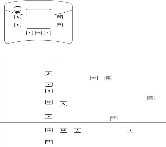
Operational Keypad
The control includes seven keypads. These functions are available to the operator and are intended to control and manage operation of the machine. Refer to
Figure 4 and Table 1.
|
|
PHM1423C |
|
|
|
|
|
|
|
|
|
|
|
|
|
|
|
|
|
|
|
|
|
|
|
|
|
|
|
|
|
|
|
|
|
Figure 4 |
|
|
|
|
|
|
|
|
|
|
|
|
|
|
|
|
|
Keypad |
|
|
|
Description |
|
|
||
|
|
|
|
|||||
|
Press to move the cursor on display to edit programming values. Also, press |
|||||||
LCD/UP ARROW |
while in Cycle Menu or Run Menu to change to the Contrast Adjust/Backlight |
|||||||
Menu. Also, press with |
and |
|
to enter System Menu. |
|
|
|||
|
|
|
|
|||||
|
|
|
|
|||||
|
|
|
|
|
||||
DOWN ARROW |
Press to move the cursor on display or edit programming values. |
|
|
|||||
|
|
|
|
|
|
|||
LEFT ARROW |
Press to move cursor on display. |
|
|
|
|
|||
|
|
|
|
|
||||
BACK |
Press to move back to the previous display menu. Also, press with |
|
and |
|||||
|
||||||||
|
to enter System Menu. Also, back from the Cycle Menu to enter the |
|||||||
|
|
|||||||
|
Service Schedule Menu. |
|
|
|
|
|
||
|
|
|
|
|||||
|
Press to move cursor on display. Press while running a cycle to get to Run |
|||||||
RIGHT ARROW
Diagnostic Menu. Press and hold with  to enter Delayed Start Menu.
|
|
|
Press to stop and abort a machine cycle during Run Mode. Also press with |
||
STOP/ON/OFF |
|
and |
to enter System Menu. Press with |
to enter Delayed Start |
|
|
|||||
|
|
|
Menu. |
|
|
|
|
|
|
||
START/ENTER |
|
|
Press to start or rapid advance a machine cycle during Run Mode. Also, press to |
||
|
|
save edited programming values when used in programming menus. |
|||
|
|
|
|||
|
|
|
|
|
|
|
|
|
|
Table 1 |
|
14 |
© Copyright, Alliance Laundry Systems LLC – DO NOT COPY or TRANSMIT |
F8434101 |

Operation Modes
General Modes of Operation
In each mode of operation, the user may press keypads or communicate with the control to change the displayed menu.
Power-up Mode
The control enters this mode at power-up. After the control completes operation in the Power-up Mode it will enter Idle Mode. The display is blank during Power-up Mode.
Idle Mode
Control is ready for operation in Idle Mode. Control can display different menus depending on user input (keypad press, opening or closing the loading door, or PC/PDA or network communication). If there is no user input for one minute, control will turn off the LCD backlight. Control will light when there is user input. If there is no user input for 10 minutes, display will go blank.
If control is in Idle Mode, Cycle Menu is displayed, loading door closed, and the  keypad is pressed, control will enter Door Locking Mode.
Door Locking Mode
The control enters this mode after the  keypad is pressed in Idle Mode. The control will stay in the Door Locking Mode until it confirms the loading door is closed and locked. The control will enter Run Mode.
Run Mode
Control enters Run Mode during a cycle. Display shows machine cycle time remaining, the colon flashing one second on/one second off indicating that the cycle time is counting down, and the display will indicate the current cycle step. Loading door is closed
and locked during Run Mode. Press  keypad to
end cycle and enter Stop Mode. Press  keypad to Rapid Advance to the next cycle step (if the Rapid Advance feature is enabled. The Rapid Advance feature is enabled by default.) Control enters Error Mode if loading door unlocks or opens.
UniLinc Identification
Stop Mode
If  keypad is pressed before cycle ends, control enters Stop Mode and performs the following steps:
•Displays a hourglass.
•Turns off all outputs.
•Verifies water is drained.
•Verifies motor is stopped by either rotation sensor or time.
•Enters Door Unlocking Mode.
Door Unlocking Mode
The control enters this mode after cycle has ended. The control waits for confirmation that door is unlocked. Once confirmation is received that door is unlocked, control will enter Idle Mode.
Error Mode
This mode will be entered to display all alarms and machine errors.
Delayed Start Countdown Mode
Delayed Start Countdown Menu is entered after delayed start is activated. The display will show the hours and minutes remaining until the machine will automatically start.
The Delayed Start Final Countdown Menu is entered during the last sixty seconds before the control is
automatically started. The  keypad will start the
selected cycle immediately. Press  to return to the Cycle Menu.
Communication Mode
This mode is entered whenever the control is communicating with a PC/PDA or through the network.
Refer to UniLinc PC and PDA Applications User
Instructions.
Entering Diagnostic Mode From Idle Mode
When entered from the Idle Mode, the control will be running a test selected by the user via keypad presses or communication with a device. The diagnostic tests available from the Idle Mode are the Test Cycle, Test Balance Weight, and Inputs Outputs Menus.
F8434101 |
© Copyright, Alliance Laundry Systems LLC – DO NOT COPY or TRANSMIT |
15 |

Machine Cycle Definition and Operation
There are 41 machine cycles which can be selected and run. Machine cycles can be modified or made “unavailable” by manually editing them in Modify Cycle Menu or by using the PC/PDA or the network to download a modified machine cycle into the control. Machine cycles cannot be deleted, but can be made “unavailable” so that they are not visible from the Cycle Menu. New machine cycles cannot be created, but existing machine cycles that have been edited to be “unavailable” may be re-edited to be available again.
Machine Cycle Operation
When a cycle is run, the control runs the cycle segment by segment and step by step in a sequence. The first segment can be programmed to “Off”, “Prewash”, “Wash” or “Rinse”. If the segment is programmed to “Off”, control skips to the next segment. If the segment is not programmed to “Off”, the first segment step (Reuse Fill step) is examined to see if it is programmed on. If the segment step is programmed on, it is executed and the next step follows until the segment is complete. Any segment steps programmed to “Off” are skipped.
At the start of a machine cycle, the control displays a Total Remaining Cycle time. This time is taken from the audit data for this cycle where there is stored an average time elapsed for the last three of these cycles that had been completed. The Total Remaining Cycle Time begins to count down as soon as the cycle is started. Since there will be differences between the average elapsed cycle time and the actual elapsed cycle time, the Total Remaining Cycle Time displayed is corrected at the start of the cycle’s final enabled step that has programmed time duration.
Delayed Start Feature
The user can select a machine cycle to run at a later time. Refer to Delayed Start Menu Section.
Cycle Menu
For Technical Service
Distributor ABC 1-800-555-5555
Cycle41: |
|
Cycle01: |
|
Cycle02: |
Supply Set |
|
Towels |
|
Towels White |
Up |
|
White |
|
|
|
|
Bleach |
|
|
|
|
|
|
|
Cycle Menu
PHM702N
Figure 5
The Cycle Menu is the first menu displayed by the control at power-up. The Cycle Menu allows the user to select one of the 41 machine cycles. Machine cycles that are turned off will not be displayed in the Cycle Menu. As a default, the last run cycle will be displayed in the center, highlighted position. The factory default cycle will be Cycle01.
16 |
© Copyright, Alliance Laundry Systems LLC – DO NOT COPY or TRANSMIT |
F8434101 |

To Start a Cycle
1.Press the  or
or  keypad to change cycles.
2.Press the  keypad to move the cycle in the rightmost menu box to the center, highlighted position.
3.Press the  keypad to move the cycle in the leftmost menu box to the center, highlighted position.
4.Moving the  and
and  keypads allows the Cycle Menu to scroll through the center, highlighted position.
5.Press  to start selected cycle.
NOTE: Press and hold  or
or  keypad to make highlighted area move rapidly.
NOTE: If door is not closed when the  keypad is pressed, display will jump to the Close Door Menu.
NOTE: If the machine has operated over 200 hours and the Lubricate Bearings has not been reset from the System Menu the Global Settings, a reminder screen will pop up. The Lubricate Bearings Menu will be display for five seconds and the Cycle Menu will display for five seconds. This will occur until the Bearing Timer is reset in the System Menu. The Lubricate Bearings Menu will only be shown during the Cycle Menu.
Every night at midnight the control will enter Service Schedule Menu if the machine is in idle mode on the Cycle Menu.
When a keypad is pressed or the door is opened or an IR communication takes place the control will turn the LCD contrast on and the backlight back on (if programmed).
Control will also enter specific service sub-menu for that day.
Quarterly Menu displays on the first day of the month for January, April, July and October.
Monthly Menu displays on all other first days of the month.
Weekly Menu displays on a Monday not on the first day of the month. All other days the control will display the Daily Menu.
Machine Cycle Definition and Operation
Press any keypad to clear the menu and enter Cycle Menu.
Optional settings are performed by either pressing a keypad or by a combination of keypad presses:
•Press the  keypad to jump control to the Contrast Adjust/Backlight Menu.
•Press the  keypad to enter the Service Schedule Menu.
•Press and hold  then
then  to enter Delayed Start Menu.
•Press and hold  then
then  then
then  to enter the System Menu.
A Banner is displayed above the Cycle Selections in the Cycle Menu. If Banner 1 and Banner 2 are programmed, Banner 1 displays for ten (10) seconds and Banner 2 displays for ten (10) seconds. If only one Banner is programmed it will be the only one shown. Refer to Banner Menu Section.
During communication with the PC/PDA, all menus enter IR Communications Menu.
F8434101 |
© Copyright, Alliance Laundry Systems LLC – DO NOT COPY or TRANSMIT |
17 |

Machine Cycle Definition and Operation
Run Menu
Cycle01: Towels White Bleach |
|
Cycle01: Towels White Bleach |
||
Segment01: Wash |
|
Segment01: Wash |
||
Fill |
|
|
Agitate |
|
HOT |
LOW |
|
HOT |
LOW |
|
S I S 2 S 3 S 4 S 5 |
|
|
|
|
E S I |
E S 5 |
|
A g i t a t e Ty p e |
|
E S 2 |
E S 6 |
|
18F/3P/18R |
|
E S 3 |
E S 7 |
|
|
|
E S 4 |
E S 8 |
|
|
Run Menu |
41:43 |
Run Menu |
38:14 |
|
|
|
PHM1071RPH |
|
PHM1006R |
Cycle01: Towels |
White Bleach |
|
Cycle01: Towels White Bleach |
|
Segment01: Wash |
|
Segment06: Rinse |
||
Drain |
|
|
Extract |
|
|
|
|
|
Extract Speed |
|
|
|
|
Very High |
Run Menu |
35:02 |
Run Menu |
05:30 |
|
|
|
PHM1005R |
|
PHM1007RPHM1 |
Figure 6
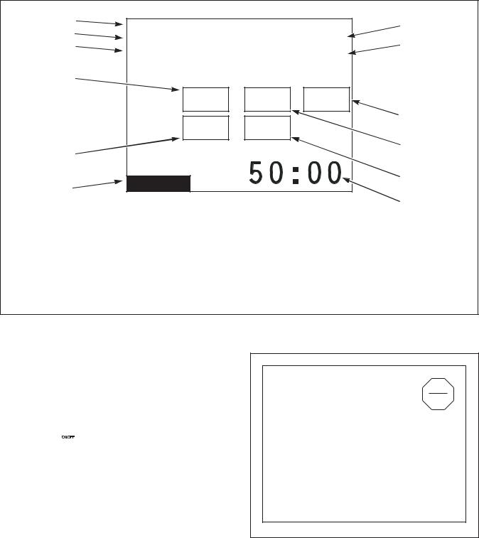
Run Menu provides cycle, segment, and step information while the machine is operating. Refer to
Figure 6.
Supplies are only shown during the fill and supply steps.
During the agitate steps the type of agitation is shown.
During the extract steps, the extraction speed displays.
18 |
© Copyright, Alliance Laundry Systems LLC – DO NOT COPY or TRANSMIT |
F8434101 |
Machine Cycle Definition and Operation
1 |
|
|
|
6 |
2 |
Cycle01: Towels White Bleach |
|
||
|
7 |
|||
3 |
Segment01: Wash |
|
||
|
Fill |
|
|
8 |
4 |
HOT |
LOW |
|
|
|
|
|||
|
|
S I S 2 S 3 S 4 S 5 |
|
|
|
|
E S I |
E S 5 |
9 |
|
|
|
||
|
|
E S 2 |
E S 6 |
|
5 |
|
E S 3 |
E S 7 |
|
|
|
E S 4 |
E S 8 |
|
10 |
Run Menu |
41:43 |
11 |
|
|
|
PHM1071R |
|
|
|
|
|
|
|
|
|
|
PHM1071N |
1 |
Cycle Name |
6 |
Water Level – OVFL, HIGH, MED, LOW |
2 |
Segment Name |
7 |
Water Level – Graphical Value/Action graphic |
3 |
Step Name |
8 |
Internal Supply Indicators |
4 |
Programmed Water Temperature - |
9 |
External Supply Indicators |
|
HOT, WARM, COLD or actual temperature |
10 |
Run Screen Indicator |
5 |
Actual Temperature – range of 32-212F |
11 |
Countdown Timer |
Figure 7
The Run Menu cannot be navigated by manipulating the arrow keypads. Press  keypad to advance the cycle one step. The Control cannot advance into a Spray Rinse Extract or an Extract Cycle Step. Advancing the steps within a cycle also depends on whether the option has been toggled on or off in the Rapid Advance Menu.
The Run menus include the Run Menu, the Run Diagnostic Menu, and the various sub-screens of the
Run Diagnostic Menu. Press the  keypad to jump to the Run Diagnostic Menu.
Press the  keypad to stop the cycle in any of the
Run menus.
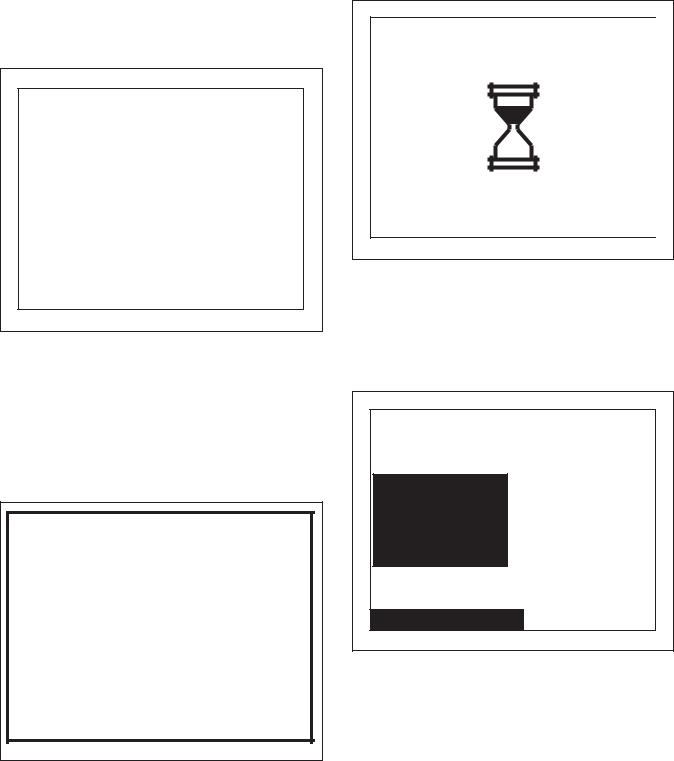
When the  keypad is pressed, the display will jump to the Cycle Stopped Menu showing an hourglass.
F8434101 |
© Copyright, Alliance Laundry Systems LLC – DO NOT COPY or TRANSMIT |
19 |
Machine Cycle Definition and Operation
Contrast/Backlight Menu
Contrast |
Backlight |
Contrast / Backlight Menu |
|
|
PHM1008R |
Figure 8
Press the  keypad from Cycle Menu or Run Menu to enter the Contrast Adjust/Backlight Menu. The Contrast Adjust/Backlight Menu allows the user to adjust contrast and turn the backlight on or off.
Press the  or
or  keypad to highlight “Contrast” or “Backlight” menu items.
Once the menu item has been selected, press the 
or  keypad to change contrast. The backlight is either on or off and will have a factory default of on.
Press the  keypad to enter the previous page.
If the Contrast Adjust/Backlight Menu is selected from the Run Menu and the  keypad is pressed, the Cycle is aborted.
Close Door Menu
PHM843N
Figure 9
The Close Door Menu displays when loading door on the machine is open and needs to be closed.
Close door to start cycle or press the  keypad to return to Cycle Menu.
20 |
© Copyright, Alliance Laundry Systems LLC – DO NOT COPY or TRANSMIT |
F8434101 |
Lubricate Bearings Menu
Lubricate Bearings!
200 Hours Have Elapsed
PHM1009R
Figure 10
The Lubricate Bearings Menu displays when the machines has run for 200 hours and the bearing is the type that can be lubricated. The Lubricate Bearings Menu displays during Idle Mode when the Cycle Menu is displayed. The Lubricate Bearing Menu and Cycle Menu will alternate being displayed.
To remove the Lubricate Bearings Menu from being shown during Idle Mode, the user must reset the bearing timer by navigating to the System Menu and reset the bearing timer. Press any keypad to display Cycle Menu while viewing Lubricate Bearings Menu.
Machine Cycle Definition and Operation
Run Diagnostic Menu
Speed, Temp
and Level
Inputs and
Outputs
Alarms
Run Diagnostic Menu
Machine ID
Drive ID
Drive Alarms
PHM1403R
Figure 11
The Run Mode Diagnostic Menu allows user to access diagnostic information of the cycle currently running. The menu contains speed, temperature, water level, inputs and outputs, alarms, machine ID, Drive ID and Drive Alarms.
While machine is running, press the  keypad to enter Run Diagnostic Menu.
Press the  ,
,  ,
,  , or
, or  keypad to navigate the menu.
Press the  keypad to choose selection.
If the  keypad is pressed, display enters Run Menu. If nothing is selected for 15 seconds, the display will return to Run Menu.
F8434101 |
© Copyright, Alliance Laundry Systems LLC – DO NOT COPY or TRANSMIT |
21 |
Machine Cycle Definition and Operation
Speed, Temp and Water Level Menu
1 |
Cycle01: Towels White Bleach |
|
4 |
||
2 |
|
||||
Segment01: Wash |
|
01:42 |
5 |
||
3 |
|
||||
Fill |
|
|
01:42 |
||
|
|
|
|
||
6 |
|
Temp |
Level |
RPM |
|
|
|
|
|
|
|
|
Actual |
138 F |
01 |
40 |
|
|
Program |
140 F |
01 |
|
10 |
|
|
|
|||
7 |
|
|
|
|
8 |
|
|
|
|
|
|
|
Run Menu |
|
|
|
9 |
11 |
|
|
|
|
|
|
|
|
|
|
|
|
|
|
|
PHM1083R |
12 |
|
|
|
|
|
|
PHM1083R
1 |
Cycle Name |
7 |
Programmed Water Temperature |
2 |
Segment Name |
8 |
Actual Water Level |
3 |
Step Name |
9 |
Programmed Water Level |
4 |
Segment Time Elapsed |
10 |
Actual RPM |
5 |
Step Time Remaining |
11 |
Run Screen Indicator |
6 |
Actual Water Temperature |
12 |
Cycle Time Remaining |
Figure 12
The Speed, Temp, and Level Menu will display the actual RPM, temperature and level, and program values of the temperature and level during run mode. The top portion of the display contains the same information listed in the Run Menu detailing Cycle, Segment, and Step operation.
Press  keypad to enter Run Mode Diagnostic
Menu. Press  keypad to stop the cycle, the control will enter Cycle Stopped if there is rotation or the Unlock Door page if there is not rotation. Press the
 keypad to advance the cycle one step. The Control cannot advance into a Spray Rinse Extract or an Extract Cycle Step. Advancing the steps within a cycle also depends on whether this option has been changed to on or off in the Rapid Advance Menu.
Cycle Aborted Retry Menu
Cycle Stopped
Heater Alarm Time Exceeded
Press START Key to Retry Press STOP Key to Abort Cycle
PHM1011R
Figure 13
The Cycle Aborted Retry Menu will be displayed for a fill, drain or heater alarm time error. The display will toggle this page with the Run Menu every three
seconds. Press  to resume the cycle.
22 |
© Copyright, Alliance Laundry Systems LLC – DO NOT COPY or TRANSMIT |
F8434101 |
Press  keypad to abort the cycle. After two minutes without a keypad press the control will abort the cycle and go to the Cycle Aborted Fatal Menu.
Cycle Aborted Fatal Menu
Cycle Aborted
Water Level Sensor Error
Press BACK Key to
Return to Cycle Menu
PHM1012R
Figure 14
The Cycle Aborted Fatal Menu will be displayed during any fatal errors or if the cycle is aborted from
the Cycle Aborted Retry Menu. Press the  keypad to exit the menu. Control will go to the Cycle Stopped Menu or the Unlock Door Menu (depending on if there is rotation or water present).
Error Menu
Door Lock Error
PHM1438R
Figure 15
The Error Menu will be displayed if an error occurs in Idle Mode. The control will return to the previously displayed menu when the error clears.
Machine Cycle Definition and Operation
Cycle Stopped Menu
PHM1013R |
Figure 16
The Cycle Stopped Menu is displayed while the control is waiting for the basket to stop spinning. After rotation is complete and the water has drained from the machine the control will go to the Unlock Door Menu.
Delayed Start Menu
Cycle01: Towels White Bleach
1 Hour
Delayed Start Menu
PHM1014R
Figure 17
The Delayed Start Menu allows user to select in how many hours the cycle should start.
Delayed Start Menu is only available from the Cycle Menu.
If the loading door is opened, if the  keypad is pressed, or if there is a power failure during the delay, the Delayed Start is aborted and is recorded as an aborted cycle in the Last 10 Cycles Rapid Advance or Stopped Audit Queue.
F8434101 |
© Copyright, Alliance Laundry Systems LLC – DO NOT COPY or TRANSMIT |
23 |
 Loading...