


 Loading...
Topload Washers
Metered and Nonmetered
Installation/Operation
Original Instructions
Keep These Instructions for Future Reference.
(If this machine changes ownership, this manual must accompany machine.)
TLW12C_SVG
www.alliancelaundry.com |
Part No. 202630R2 |
|
September 2016 |
WARNING
Failure to install, maintain, and/or operate this machine according to the manufacturer's instructions may result in conditions which can produce bodily injury and/or property damage.
W030
WARNING
For your safety and to reduce the risk of fire or an explosion, do not store or use gasoline or other flammable vapors and liquids in the vicinity of this or any other appliance.
W022
NOTE: The WARNING and IMPORTANT instructions appearing in this manual are not meant to cover all possible conditions and situations that may occur. It must be understood that common sense, caution, and carefulness are factors which cannot be built into these washers. These factors MUST BE supplied by the person(s) installing, maintaining, or operating the washer.
Always contact the distributor, service agent, or the manufacturer about any problems or conditions you do not understand.
Read all instructions before using washer.
© Copyright, Alliance Laundry Systems LLC - |
3 |
Part No. 202630R2 |
DO NOT COPY or TRANSMIT |
|
|
Table of Contents |
|
Safety Information.................................................................................. |
6 |
Explanation of Safety Messages....................................................................... |
6 |
Important Safety Instructions........................................................................... |
6 |
Dimensions............................................................................................. |
8 |
Installation........................................................................................... |
10 |
Before You Start........................................................................................... |
10 |
Tools........................................................................................................ |
10 |
Order of Installation Steps.......................................................................... |
10 |
Remove the Shipping Brace and Shipping Plug............................................... |
10 |
Wipe Out Inside of Wash Tub......................................................................... |
11 |
Connect Fill Hoses........................................................................................ |
11 |
Water Supply Requirements....................................................................... |
12 |
Connecting Hoses...................................................................................... |
12 |
Risers....................................................................................................... |
12 |
Connect Drain Hose to Drain Receptacle......................................................... |
13 |
Drain Facilities.......................................................................................... |
13 |
High Standpipe Installation........................................................................ |
13 |
Low Standpipe Installation......................................................................... |
14 |
Position and Level the Washer........................................................................ |
14 |
Plug In the Washer........................................................................................ |
15 |
Electrical Requirements............................................................................. |
15 |
Earth/Ground Instructions.......................................................................... |
16 |
Add Water to the Washer............................................................................... |
16 |
Check Lid Switch......................................................................................... |
16 |
Check Installation......................................................................................... |
16 |
Vending....................................................................................................... |
17 |
Meter Case............................................................................................... |
17 |
Slide Extension Assembly.......................................................................... |
17 |
Models Prepped for Card Reader and Non-Metered Models.......................... |
18 |
Additional Security.................................................................................... |
18 |
Operation............................................................................................. |
20 |
Operation Instructions for Coin Slide Operated and Nonmetered Washers.......... |
20 |
Add Detergent........................................................................................... |
20 |
Load Laundry........................................................................................... |
20 |
Close Lid.................................................................................................. |
20 |
Set Wash Temperature and Fabric/Cycle Selector......................................... |
20 |
Start Washer.............................................................................................. |
21 |
Indicator Lights......................................................................................... |
22 |
© Copyright 2016, Alliance Laundry Systems LLC
All rights reserved. No part of the contents of this book may be reproduced or transmitted in any form or by any means without the expressed written consent of the publisher.
© Copyright, Alliance Laundry Systems LLC - |
4 |
Part No. 202630R2 |
DO NOT COPY or TRANSMIT |
|
|
Control Modes.......................................................................................... |
22 |
Rapid Advance.......................................................................................... |
23 |
Setting Dipswitch...................................................................................... |
23 |
Operation Instructions for MDC Washers........................................................ |
23 |
Add Detergent........................................................................................... |
23 |
Load Laundry........................................................................................... |
23 |
Close Lid.................................................................................................. |
24 |
Set Fabric Selector and Wash Temperature................................................... |
24 |
Insert Coins or Card................................................................................... |
24 |
Start Washer.............................................................................................. |
24 |
Indicator Lights......................................................................................... |
25 |
Maintenance......................................................................................... |
26 |
User-Maintenance Instructions....................................................................... |
26 |
Cold Weather Care.................................................................................... |
26 |
Care of Your Washer.................................................................................. |
26 |
Replacing Hoses........................................................................................ |
26 |
Filter Screens............................................................................................ |
26 |
Reinstallation of Shipping Materials............................................................... |
26 |
Shipping Brace.......................................................................................... |
26 |
Shipping Plug........................................................................................... |
26 |
Motor Overload Protector.............................................................................. |
26 |
Troubleshooting.................................................................................... |
28 |
Contact Information............................................................................. |
30 |
Installer Checklist................................................................................. |
31 |
© Copyright, Alliance Laundry Systems LLC - |
5 |
Part No. 202630R2 |
DO NOT COPY or TRANSMIT |
|
|
Safety Information
Safety Information
Explanation of Safety Messages |
Important Safety Instructions |
Precautionary statements (“DANGER,” “WARNING,” and “CAUTION”), followed by specific instructions, are found in this manual and on machine decals. These precautions are intended for the personal safety of the operator, user, servicer, and those maintaining the machine.
DANGER
Indicates an imminently hazardous situation that, if not avoided, will cause severe personal injury or death.
WARNING
Indicates a hazardous situation that, if not avoided, could cause severe personal injury or death.
CAUTION
Indicates a hazardous situation that, if not avoided, may cause minor or moderate personal injury or property damage.
Additional precautionary statements (“IMPORTANT” and “NOTE”) are followed by specific instructions.
IMPORTANT: The word “IMPORTANT” is used to inform the reader of specific procedures where minor machine damage will occur if the procedure is not followed.
NOTE: The word “NOTE” is used to communicate installation, operation, maintenance or servicing information that is important but not hazard related.
Save These Instructions
WARNING
To reduce the risk of fire, electric shock, serious injury or death to persons when using your washer, follow these basic precautions:
W023
•Read all instructions before using the washer.
•Install the washer according to the INSTALLATION INSTRUCTIONS. Refer to the EARTH/GROUND INSTRUCTIONS in the INSTALLATION manual for the proper earth/ ground connection of the washer. All connections for water, drain, electrical power and earth/ground must comply with local codes and be made by licensed personnel when required. Do not do it yourself.
•Do not install or store the washer where it will be exposed to water and/or weather.
•Do not add the following substances or textiles containing traces of the following substances to the wash water: gasoline, kerosene, waxes, cooking oils, vegetable oils, machine oils, dry-cleaning solvents, flammable chemicals, thinners or other flammable or explosive substances. These substances give off vapors that could ignite, explode or cause the fabric to catch on fire by itself.
•Under certain conditions, hydrogen gas may be produced in a hot water system that has not been used for two weeks or more. HYDROGEN GAS IS EXPLOSIVE. If the hot water system has not been used for such a period, before using a washing machine or combination washer-dryer, turn on all hot water faucets and let the water flow from each for several minutes. This will release any accumulated hydrogen gas. THE GAS IS FLAMMABLE, DO NOT SMOKE OR USE AN OPEN FLAME DURING THIS TIME.
•To reduce the risk of an electric shock or fire, DO NOT use an extension cord or an adapter to connect the washer to the electrical power source.
•Do not allow children to play on or in the washer. Close supervision of children is necessary when the washer is used near children. This appliance is not intended for use by persons (including children) with reduced physical, sensory or mental capabilities, or lack of experience and knowledge, unless they have been given supervision or instruction concerning the use of the appliance by a person responsible for their safety. This is a safety rule for all appliances.
•Cleaning and user maintenance shall not be made by children without supervision.
© Copyright, Alliance Laundry Systems LLC - |
6 |
Part No. 202630R2 |
DO NOT COPY or TRANSMIT |
|
|
•Children less than three years should be kept away unless continuously supervised.
•Do not reach into the washer if the washtub or agitator, if applicable, is moving.
•Never operate the washer with any guards, panels and/or parts removed or broken. DO NOT tamper with the controls or bypass any safety devices.
•Use your washer only for its intended purpose, washing clothes. Always follow the fabric care instructions supplied by the garment manufacturer.
•Always read and follow manufacturer’s instructions on packages of laundry and cleaning aids. To reduce the risk of poisoning or chemical burns, keep them out of the reach of children at all times (preferably in a locked cabinet). Heed all warnings or precautions.
•Do not use fabric softeners or products to eliminate static unless recommended by the manufacturer of the fabric softener or product.
•Lid MUST BE CLOSED any time the washer is to agitate or spin. DO NOT bypass the lid switch to permit the washer to agitate or spin with the lid open. A brake will stop the washtub within seconds if the lid is opened during spinning. If the washtub does not stop when the lid is opened, remove the washer from use and call the service person.
•Be sure water connections have a shut-off valve and that fill hose connections are tight. CLOSE the shut-off valves at the end of each wash day.
•Keep your washer in good condition. Bumping or dropping the washer can damage safety features. If this occurs, have your washer checked by a qualified service person.
•Do not repair or replace any part of the washer, or attempt any servicing unless specifically recommended in the user-mainte- nance instructions or in published user-repair instructions that you understand and have the skills to carry out. ALWAYS disconnect the washer from electrical supply before attempting any service.
•Disconnect the power cord by grasping the plug, not the cord. If the supply cord is damaged, it must be replaced by the manufacturer, its service agent or similarly qualified persons in order to avoid a hazard.
•Before the washer is removed from service or discarded, remove the lid or door to the washing compartment.
•Failure to install, maintain, and/or operate this washer according to the manufacturer’s instructions may result in conditions which can produce bodily injury and/or property damage.
NOTE: The WARNING and IMPORTANT SAFETY INSTRUCTIONS appearing in this manual are not meant to cover all possible conditions and situations that may occur. Observe and be aware of other labels and precautions that are located on the machine. They are intended to provide instruction for safe use of the machine. Common sense, caution and care must be exercised when installing, maintaining, or operating the washer.
Safety Information
Always contact your dealer, distributor, service agent or the manufacturer about any problems or conditions you do not understand.
© Copyright, Alliance Laundry Systems LLC - |
7 |
Part No. 202630R2 |
DO NOT COPY or TRANSMIT |
|
|
Dimensions
|
Dimensions |
|
|
||
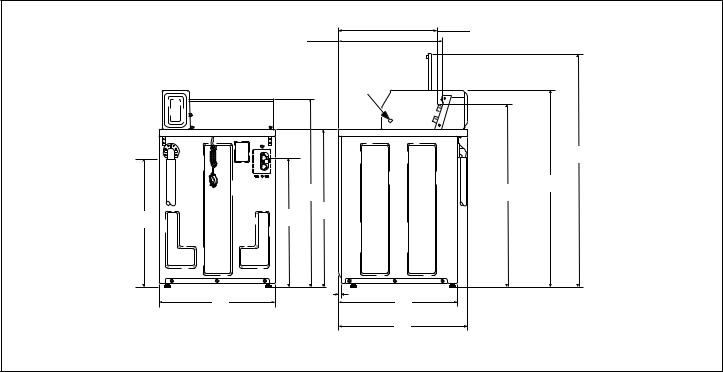
Metered Models |
|
|
|
|
|
|
|
A |
|
B |
|
|
|
|
|
|
|
|
|
|
1 |
|
|
|
C |
|
|
|
C |
|
H |
|
|
|
|
|
|
J |
|
E |
D |
|
|
|
|
||
M |
K |
I |
|
|
|
|
|
|
|
||
L |
|
H |
G |
|
|
|
|
|
|
||
|
|
|
F |
|
TLW2051N_SVG |
1. Pilot Hole
A - Electronic Control Models |
570 mm [22.44 in.] |
|
|
B - Coin Slide Models |
548 mm [21.56 in.] |
|
|
C |
1295 mm [51 in.] |
|
|
D |
1092 mm [43 in.] |
|
|
E - Electronic Control Models |
970 mm [38.19 in.] |
|
|
E - Coin Slide Models |
1026 mm [40.38 in.] |
|
|
F |
711 mm [28 in.] |
|
|
G |
660 mm [26 in.] |
|
|
H |
11 mm [0.44 in.] |
|
|
I |
914 mm [36 in.] |
|
|
J |
1048 mm [41.25 in.] |
|
|
K |
730 mm [28.75 in.] |
|
|
L |
651 mm [25.63 in.] |
|
|
M |
775 mm [30.5 in.] |
|
|
© Copyright, Alliance Laundry Systems LLC - |
8 |
Part No. 202630R2 |
DO NOT COPY or TRANSMIT |
|
|
Dimensions
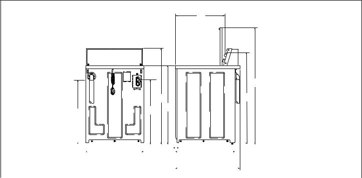
Nonmetered Models
A
C |
B |
H |
|
H |
C |
K |
I |
G |
|
||
|
|
|
|
|
|
|
|
|
|
|
|
|
|
|
|
|
|
|
|
|
|
|
|
|
|
|
|
|
|
|
|
|
|
|
|
|
|
|
|
|
|
|
|
|
|
|
|
|
|
|
|
|
|
|
|
|
|
|
|
|
|
|
|
|
|
|
|
|
|
|
|
|
|
|
|
|
F |
|
|
|
|
|
|
|
|
|
|
|
|
|
|
|
|
|
|
|
|
|
|
|
|
J |
|
|
|
|
|
|
|
|
|
|
E |
|
|
|
|
|
|
TLW2050N_SVG |
|||||
|
|
|
|
|
|
|
|
|
|
|
|
|
|
|
|
|
|
|
|
|
|
|
|
|
|
|||||
|
|
|
|
|
|
|
|
|
|
|
|
|
|
|
|
|
|
|
|
|
|
|
|
|
|
|
|
|
||
|
|
|
|
|
|
|
|
|
|
|
|
|
|
|
|
|
|
|
|
|
|
|
|
|
|
|
|
|
||
|
|
|
|
|
|
|
|
|
|
|
|
|
|
|
|
|
|
|
|
|
|
|
D |
|
|
|
|
|
|
|
|
|
|
|
|
|
|
|
|
|
|
|
|
|
|
|
|
|
|
|
|
|
|
|
|
|
|
||||
|
|
|
|
|
|
|
|
|
|
|
|
|
|
|
||||||||||||||||
|
|
|
|
|
|
|
|
|
|
|
|
|
|
|
||||||||||||||||
A |
|
|
|
|
|
|
|
|
|
|
|
548 mm [21.56 in.] |
||||||||||||||||||
|
|
|
|
|
|
|
|
|
|
|
|
|
|
|
||||||||||||||||
B |
|
|
|
|
|
|
|
|
|
|
|
1295 mm [51 in.] |
||||||||||||||||||
|
|
|
|
|
|
|
|
|
|
|
|
|
|
|
||||||||||||||||
C |
|
|
|
|
|
|
|
|
|
|
|
1026 mm [40.38 in.] |
||||||||||||||||||
|
|
|
|
|
|
|
|
|
|
|
|
|
|
|
||||||||||||||||
D |
|
|
|
|
|
|
|
|
|
|
|
711 mm [28 in.] |
||||||||||||||||||
|
|
|
|
|
|
|
|
|
|
|
|
|
|
|
||||||||||||||||
E |
|
|
|
|
|
|
|
|
|
|
|
660 mm [26 in.] |
||||||||||||||||||
|
|
|
|
|
|
|
|
|
|
|
|
|
|
|
||||||||||||||||
F |
|
|
|
|
|
|
|
|
|
|
|
11 mm [0.44 in.] |
||||||||||||||||||
|
|
|
|
|
|
|
|
|
|
|
|
|
|
|
||||||||||||||||
G |
|
|
|
|
|
|
|
|
|
|
|
914 mm [36 in.] |
||||||||||||||||||
|
|
|
|
|
|
|
|
|
|
|
|
|
|
|
||||||||||||||||
H |
|
|
|
|
|
|
|
|
|
|
|
1048 mm [41.25 in.] |
||||||||||||||||||
|
|
|
|
|
|
|
|
|
|
|
|
|
|
|
||||||||||||||||
I |
|
|
|
|
|
|
|
|
|
|
|
730 mm [28.75 in.] |
||||||||||||||||||
|
|
|
|
|
|
|
|
|
|
|
|
|
|
|
||||||||||||||||
J |
|
|
|
|
|
|
|
|
|
|
|
651 mm [25.63 in.] |
||||||||||||||||||
|
|
|
|
|
|
|
|
|
|
|
|
|
|
|
||||||||||||||||
K |
|
|
|
|
|
|
|
|
|
|
|
775 mm [30.5 in.] |
||||||||||||||||||
|
|
|
|
|
|
|
|
|
|
|
|
|
|
|
|
|
|
|
|
|
|
|
|
|
|
|
|
|
|
|
© Copyright, Alliance Laundry Systems LLC - |
9 |
Part No. 202630R2 |
DO NOT COPY or TRANSMIT |
|
|
Installation
Installation
Before You Start
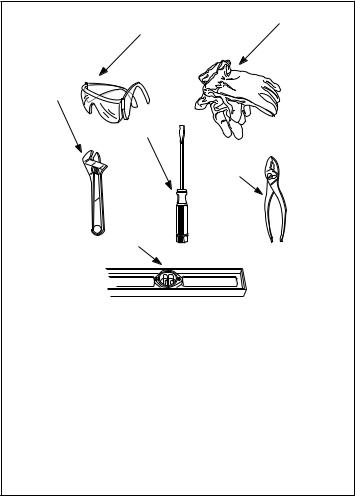
Tools
For most installations, the basic tools you will need are:
2
1
3
4
5
6
TLW2215N_SVG
NOTE: A cloth rag and all-purpose cleaner are also needed.
1.Safety Glasses
2.Gloves
3.Wrench
4.Screwdriver
5.Pliers
6.Level
Figure 1
1.Remove the shipping brace and shipping plug.
2.Wipe out inside of the washer.
3.Connect the fill hoses.
4.Connect the drain hose to the drain receptacle.
5.Position and level the washer.
6.Plug in the washer.
7.Add water to the washer.
8.Check the lid switch.
9.Check installation.
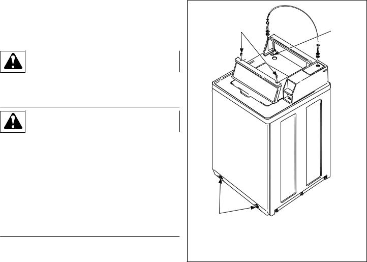
Remove the Shipping Brace and
Shipping Plug
1.Remove the shipping brace from under the lid.
2.The shipping plug will be released from the base of the washer when removing the cardboard base from the washer. Refer to Figure 2 .
The shipping brace and plug should be saved and must be reinstalled whenever washer is moved or transported to a new location. This will prevent damage to washer components.
Do not tilt washer to front or sides when moving.
Refer to User-Maintenance section for instructions on reinstalling shipping brace and shipping plug.
NOTE: If the washer is delivered on a cold day (below freezing), or is stored in an unheated room or area during the cold months, do not attempt to operate it until the washer has had a chance to warm up.
NOTE: Install dryer before washer. This allows room for attaching exhaust duct.
NOTE: This appliance is suitable for use in countries having a warm, damp climate.
Order of Installation Steps
The proper order of steps must be followed to ensure correct installation. Refer to the list below when installing your unit.
© Copyright, Alliance Laundry Systems LLC - |
10 |
Part No. 202630R2 |
DO NOT COPY or TRANSMIT |
|
|

Installation
1
3
2
TLW2098N_svg
1.Shipping Brace
2.Shipping Plug
3.Cardboard Base
Figure 2
Wipe Out Inside of Wash Tub
Prior to first wash, use an all purpose cleaner or a detergent and water solution and a damp cloth to remove shipping dust from inside of the washer.
TLW2099N_SVG
Figure 3
Connect Fill Hoses
WARNING
Under certain conditions, hydrogen gas may be produced in a hot water system that has not been used for two weeks or more. HYDROGEN GAS IS EXPLOSIVE. If the hot water system has not been used for such a period and before using the washer, turn on all hot water faucets and let the water flow from each for several minutes. This will release any accumulated hydrogen gas. The gas is flammable. Do not smoke or use an open flame during this time.
|
|
|
|
|
W029 |
|
|
|
|
|
|
|
|
|
|
|
|
Mixing Valve Flow Rates |
|
|
|||
|
|
|
|
|
|
Pressure |
HOT |
|
COLD |
WARM |
|
kPa [psi] |
liters per mi- |
|
liters per mi- |
liters per mi- |
|
|
|
nute [gallons |
|
nute [gallons |
nute [gallons |
|
|
per minute] |
|
per minute] |
per minute] |
|
|
|
|
|
|
138 |
[20] |
12.9 [3.4] |
|
12.9 [3.4] |
15.1 [4.0] |
|
|
|
|
|
|
827 |
[120] |
17.4 [4.6] |
|
17.4 [4.6] |
17.4 [4.6] |
|
|
|
|
|
|
© Copyright, Alliance Laundry Systems LLC - |
11 |
Part No. 202630R2 |
DO NOT COPY or TRANSMIT |
|
|
Installation
Water Supply Requirements
Water supply faucets must fit standard 19 mm [3/4 inch] female garden hose couplings. DO NOT USE SLIP-ON OR CLAMPON CONNECTIONS.
NOTE: Water supply faucets should be readily accessible to permit turning them off when washer is not being used.
Recommended cold water temperature is 10° to 24° Celsius [50° to 75° Fahrenheit]. Recommended maximum hot water temperature is 51° Celsius [125° Fahrenheit]. Warm water is a mixture of hot and cold water. Warm water temperature is dependent upon the water temperature and the pressure of both the hot and cold water supply lines.
WARNING
To prevent personal injury, avoid contact with inlet water temperatures higher than 51° Celsius [125° Fahrenheit] and hot surfaces.
W748
Water pressure must be a minimum of 138 to a maximum of 827 kPa [minimum of 20 to a maximum of 120 pounds per square inch] static pressure measured at the faucet.
NOTE: Water pressure under 138 kPa [20 pounds per square inch] will cause an extended fill time in the washer and decreased rinse performance.
Turn on the water supply faucets and flush the lines for approximately two minutes to remove any foreign materials that could clog the screens in the water mixing valve. This is especially important when installing your washer in a newly constructed or renovated building. Build-up may have occurred during construction.
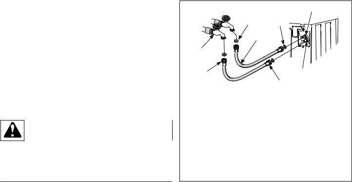
Connecting Hoses
1.Insert rubber washers and filter screens (from accessories bag) in water fill hose couplings (two hoses supplied with washer). The filter screen must be facing outward.
2.Connect fill hose couplings with filter screens to water supply faucets.
3.Connect the other hose couplings to the hot and cold valve connections at the rear of the washer.
4.Thread hose couplings onto valve connections finger tight. Then turn 1/4 turn with pliers.
IMPORTANT: DO NOT cross thread or overtighten couplings. This will cause them to leak.
5.Turn water on and check for leaks.
6.If leaks are found, retighten the hose couplings.
7.Continue tightening and rechecking until no leaks are found.
4
COLD |
1 |
3 |
HOT
2
8
7 |
5 |
|
|
|
6 |
TLW1988N_SVG
1.Filter Screen (Screen must be facing outward)
2.Fill Hose
3.Rubber Washer (Plain)
4.Cold Water Connection
5.Hot Water Connection
6.Install this end of hose to valve connections at rear of washer.
7.Install this end of hose to water supply faucet.
8.Faucet
Figure 4
IMPORTANT:
Hoses and other natural rubber parts deteriorate after extended use. Hoses may develop cracks, blisters or material wear from the temperature and constant high pressure they are subjected to.
All hoses should be checked on a monthly basis for any visible signs of deterioration. Any hose showing the signs of deterioration listed above should be replaced immediately. All hoses should be replaced every five years.
IMPORTANT: Turn off water supply faucets after checkout and demonstration. Owner should turn off water supply whenever there will be an extended period of non-use.
NOTE: Longer fill hoses are available (as optional equipment at extra cost) if the hoses (supplied with the washer) are not long enough for the installation. Order hoses as follows:
•No. 20617 Fill Hose: 2.44 m [8 feet] (2 GHT hose couplings)
•No. 20618 Fill Hose: 3.05 m [10 feet] (2 GHT hose couplings)
Risers
Risers (or air cushions) may have to be installed if the pipes knock or pound when flow of water stops. The risers are more efficient when installed as close as possible to the water supply faucets. Refer to Figure 5 .
© Copyright, Alliance Laundry Systems LLC - |
12 |
Part No. 202630R2 |
DO NOT COPY or TRANSMIT |
|
|
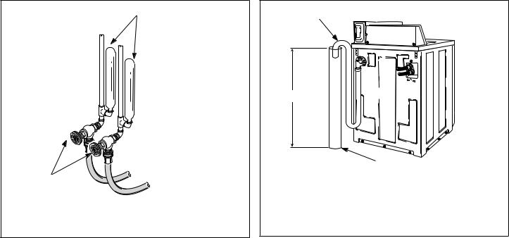
1
2
W005I_SVG
1.Risers (Air cushions)
2.Water Supply Faucets
Figure 5
Connect Drain Hose to Drain
Receptacle
IMPORTANT: The drain hose installation is a very important factor in the washer installation. If care is not taken when the drain hose is installed, a siphoning action can be started which will cause water to be siphoned from the washer during the cycle.
Drain Facilities
End of drain hose should never be in water as siphoning action can be started that will cause water to be siphoned back into the washer.
The curved end of drain hose MUST be installed even with or above the height of the cabinet top of the washer to prevent siphoning. Refer to Figure 6 .
Installation
1
3
2 |
TLW2251N_SVG |
1.Drain Hose
2.Standpipe
3.Recommended Standpipe Height 914 mm [36 in.] Minimum
Figure 6
The standpipe or drain receptacle must be capable of handling a minimum of 38 mm [1-1/2 inches] outside diameter drain hose. The drain hose should fit loose within the standpipe (it should not be snug fit). Never install the drain hose into a “sealed” drain system as air cannot escape and will restrict the water from being drained from the washer. A sealed drain system may also allow water to be pumped back into the washer during agitation. Both of these conditions may result in flooding of the washer.
Remove the drain hose from its shipping position on the rear of the washer by unhooking the hose from the retainer clamp.
If necessary, follow the instructions for your type of drain receptacle (high standpipe or low standpipe) to properly install the drain hose.
High Standpipe Installation
NOTE: No. 562P3 Siphon Break Kit and No. 25863 Hose Coupling are not required for this type of installation.
© Copyright, Alliance Laundry Systems LLC - |
13 |
Part No. 202630R2 |
DO NOT COPY or TRANSMIT |
|
|
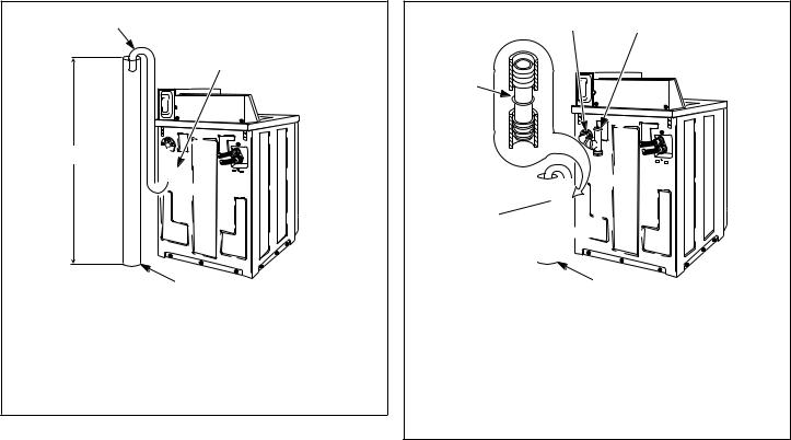
Installation
1
2
4 


 {
{
3TLW2210N_SVG
1.Drain Hose
2.Cut Drain Hose off at This End to Fit the Washer Installation
3.Standpipe
4.Maximum Standpipe Height Not To Exceed 1.5 m [5 ft.]
Figure 7
IMPORTANT: Drain receptacle must be capable of handling a minimum of 38 mm [1-1/2 inch] outside diameter drain hose.
Low Standpipe Installation
If the drain facility is lower than the cabinet top, a siphon break kit, Part No. 562P3, must be installed in the drain hose to prevent siphoning action and drain hose MUST be cut to fit the washer installation. Refer to Figure 8 . Use one No. 25863 Hose Coupling to splice hose. The No. 562P3 Siphon Break Kit and No. 25863 Hose Coupling are available as optional equipment at extra cost through an authorized dealer or parts distributor. Installation instructions are supplied with the kit.
OPTIONAL: Raise the standpipe to the recommended height of 914 mm [36 inches].
IMPORTANT: Drain receptacle must be capable of handling a minimum of 38 mm [1-1/2 inch] outside diameter drain hose.
12
5

 {
{

4
3
TLW2211N_SVG
1.Drain Hose Elbow
2.562P3 Siphon Break Kit
3.Standpipe
4.Cut Hose in This Area and Install No. 25863 Hose Coupling
5.25863 Hose Coupling
Figure 8
Position and Level the Washer
1.Position washer so it has sufficient clearance for installation and servicing.
2.Place washer in position on a clean, dry, and reasonably firm floor. Installing the washer on any type of carpeting is not recommended.
3.Place rubber cups (from accessories bag) on all four leveling legs.
4.Place a level on the cabinet top and check if the washer is level from side to side and front to back.
5.If washer is not level, tilt washer back to access the front leveling legs. Loosen the locknuts and adjust legs by screwing into or out of washer base.
6.Once adjusted, tilt the washer forward on front legs and lower back down into position to set the rear self-leveling legs.
7.Washer must not rock. When washer is level and does not rock, tighten locknuts securely against bottom of washer base. If these locknuts are not tight, washer will not remain stationary during operation.
Improper installation or flexing of weak floor will cause excessive vibration.
Do not slide washer across floor once the leveling legs have been extended, as legs and base could become damaged.
© Copyright, Alliance Laundry Systems LLC - |
14 |
Part No. 202630R2 |
DO NOT COPY or TRANSMIT |
|
|
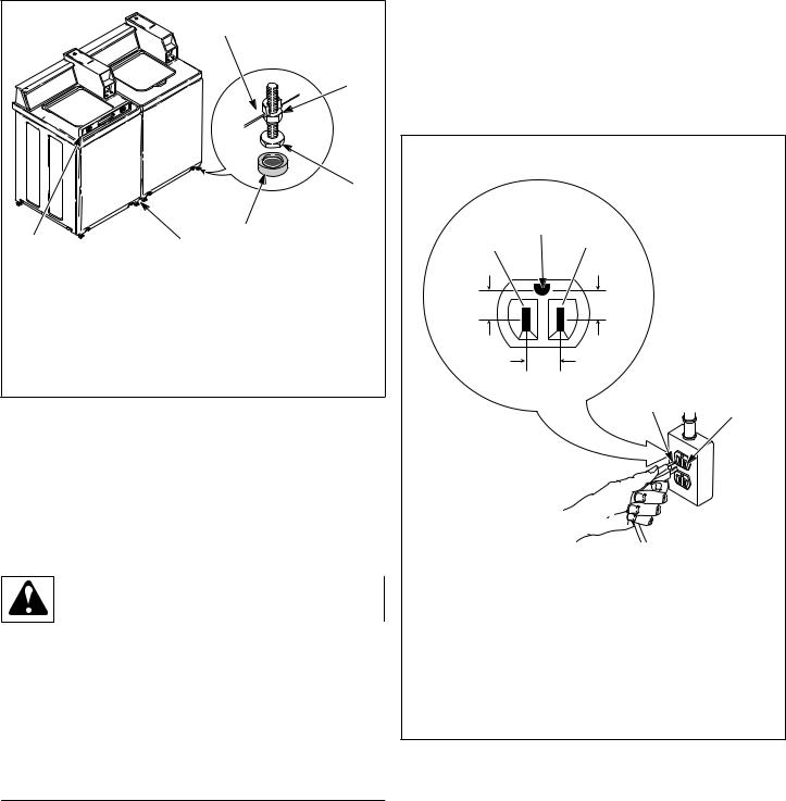
NOTE: For areas with uneven floors, a No. 566P3 Adjustable Rear Leg Extension Kit is available as optional equipment at extra cost.
8. Verify that unit does not rock.
|
|
1 |
|
|
|
|
2 |
|
|
|
3 |
|
6 |
4 |
|
|
5 |
TLW2100N_SVG |
|
1. |
Washer Base |
|
|
2. |
Locknut |
|
|
3. |
Leveling Leg |
|
|
4. |
Rubber Cup |
|
|
5. |
13 mm [1/2 inch] Clearance Between Washers |
|
|
6. |
Level |
|
|
Figure 9
Plug In the Washer
Electrical Requirements
120 Volt, 60 Hertz with 3-Prong Earth/Ground Plug
NOTE: The wiring diagram is located in the control hood.
WARNING
To reduce the risk of fire, electrical shock or personal injury, all wiring and grounding MUST conform with the latest edition of the Canadian Electrical Code, Parts I and II, and such local regulations as might apply. It is the customer’s responsibility to have the wiring and fuses checked by a qualified electrician to make sure the laundry room has adequate electrical power to operate the washer.
W110
When plugging in the washer:
•DO NOT overload circuits.
•DO NOT use an extension cord.
•DO NOT use an adapter.
Installation
•DO NOT operate other appliances on the same circuit. Use separately fused 15 Amp circuits.
The washer is designed to be operated on a separate branch, polarized, three-wire, effective earth/ground, 120 Volt, 60 Hertz, AC (alternating current), circuit protected by a 15 ampere fuse, equivalent fusetron or circuit breaker.
The three-prong earth/ground plug on the power cord should be plugged directly into a polarized three-slot effective earth/ground receptacle rated 110/120 Volts AC (alternating current) 15 Amps. Refer to Figure 10 to determine correct polarity of the wall receptacle.
Standard 120 Volt, 60 Hertz 3-Wire Effective Earth/
Ground Circuit
|
2 |
1 |
3 |
8


 6
6
7
4 |
5 |
|
DRY2022N_SVG
1.L1
2.Earth/Ground
3.Neutral Side
4.Round Earth/Ground Prong
5.Neutral
6.0 V.A.C.
7.120 ± 12 V.A.C.
8.120 ± 12 V.A.C.
Figure 10
© Copyright, Alliance Laundry Systems LLC - |
15 |
Part No. 202630R2 |
DO NOT COPY or TRANSMIT |
|
|

Installation
WARNING
To reduce the risk of an electric shock or fire, DO NOT use an extension cord or an adapter to connect the washer to the electric power source.
W082
Earth/Ground Instructions
This appliance must be properly connected to protective earth/ ground. In the event of malfunction or breakdown, the earth/ ground will reduce the risk of electric shock by providing a path of least resistance for electric current.
The appliance is equipped with a cord having an equipment earth/ ground conductor and a three-prong earth/ground plug. The plug must be plugged into an appropriate outlet that is properly installed and connected to a protective earth/ground in accordance with all local codes and ordinances.
WARNING
Improper connection of the equipment earth/ground conductor can result in a risk of electric shock. Check with a qualified electrician or service person if you are in doubt as to whether the unit is properly connected to a protective earth/ground.
W893
•DO NOT modify the plug provided with the unit – if it will not fit the outlet, have a proper outlet installed by a qualified electrician.
•If the laundry room’s electrical supply does not meet the above specifications and/or if you are not sure the laundry room has an effective earth/ground, have a qualified electrician or your local electrical utility company check it and correct any problems.
WARNING
Any disassembly requiring the use of tools must be performed by a suitably qualified service person.
W299
WARNING
This unit is equipped with a three-prong (earth/ ground) plug for your protection against shock hazard and should be plugged directly into a protective earth/ ground three-prong receptacle. Do not cut or remove the earth/ground prong from this plug.
W823
Add Water to the Washer
To prevent damage to pump, do not run washer before adding at least 0.95 liter [one quart] water to the tub. If the washer is run before any water is added, the pump seal may overheat, causing the pump to leak. Once installed, the water retained in the drain system from the previous cycle will provide sufficient cooling to prevent pump seal damage.
NOTE: The agitator should not be removed except for service. The washtub is designed to be self-cleaning.
TLW2056N_SVG
Figure 11
Check Lid Switch
Washer should stop filling, agitating and spinning when lid is opened during a wash cycle.
TLW2101N_SVG
Figure 12
Check Installation
1.Refer to Installer Checklist on the back cover of this manual and make sure that washer is installed correctly.
© Copyright, Alliance Laundry Systems LLC - |
16 |
Part No. 202630R2 |
DO NOT COPY or TRANSMIT |
|
|
2.Run washer through one complete cycle to make sure it is operating properly.
Vending
Meter Case
The factory mounted coin meter case does not include the service door lock, coin slide (if applicable), coin drawer, coin drawer lock or keys. These parts must be ordered (at extra cost) according to the purchaser’s requirements direct from the manufacturer of your choice.
NOTE: You have the option of using a screw type lock or a 1/4 turn lock on the meter case service door. If you choose to use a screw lock, then the special bracket (located inside the meter case) must be used. DO NOT use the special bracket if a 1/4 turn lock is used.
Coin Drawer Security - For additional security, drill out the two pilot holes on each side of the front of the meter case to 6.4 or 7.9 mm [1/4 or 5/16 inch] holes and install a bicycle lock through these holes.
NOTE: An 203 mm [8 in.] coin drawer is required for coin operated electronic control models.
Slide Extension Assembly
1.Remove slide extension parts from parts accessories bag included in unit.
2.Install extension lever with arm that has one star facing down. Refer to Figure 13 .
1
TLW2160N_SVG
1. One Star
Figure 13
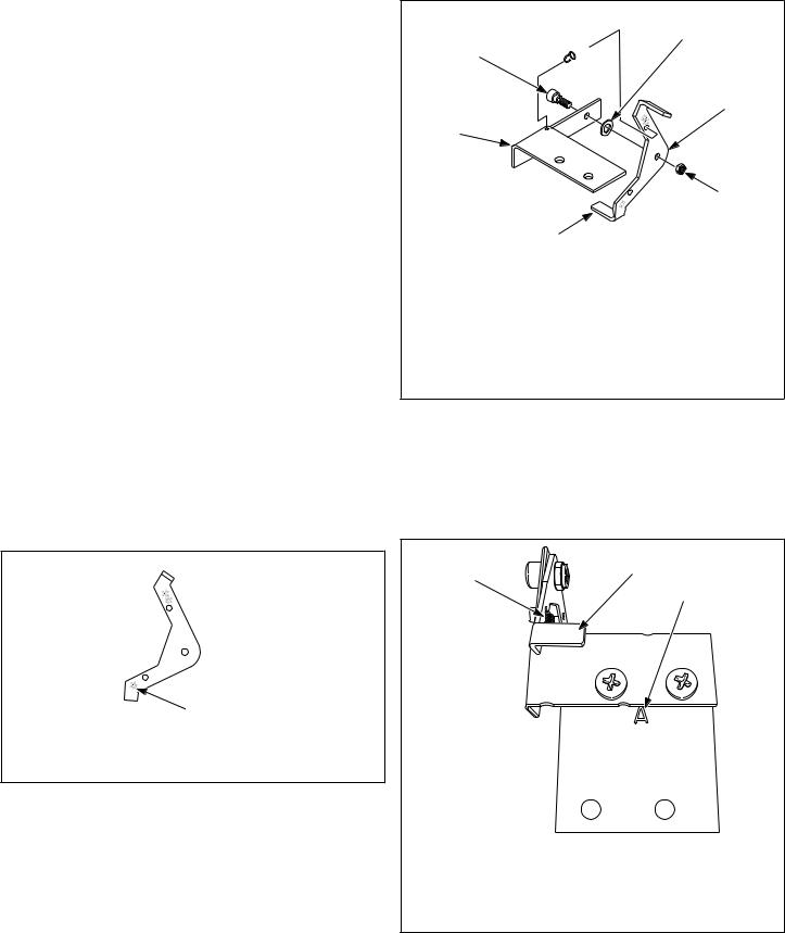
3.Install extension lever with rounded corner facing away from extension bracket using shoulder bolt, flat washer and nut. Refer to Figure 14 .
4.Install spring to extension bracket with hook facing down. Install other end of spring to extension lever with hook facing left while standing in front of unit. Refer to Figure 14 .
Installation
2
 3 1
3 1 


4
7
5
6 |
TLW1610K_SVG |
1.Shoulder Bolt
2.Spring
3.Flat Washer
4.Rounded Corner
5.Nut
6.Extension Lever
7.Extension Bracket
Figure 14
5.Install extension bracket and lever assembly onto coin slide bracket using two screws and locknuts. Refer to Figure 15 .
IMPORTANT: Install coin slide bracket with side marked “A” facing up and toward extension bracket and lever assembly. Refer to Figure 15 .
1 |
2 |
|
3
TLW2163N_SVG
1.Spring Installed
2.Extension Bracket and Lever Assembly
3.Coin Slide Bracket - Letter "A"
Figure 15
© Copyright, Alliance Laundry Systems LLC - |
17 |
Part No. 202630R2 |
DO NOT COPY or TRANSMIT |
|
|
Installation
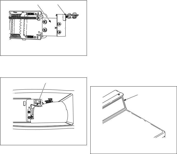
6.Install coin slide extension assembly onto top of coin slide using two remaining screws and lockwashers. Place lockwasher under head of screws, above bracket “A”. Refer to Figure 16 .
|
1 |
2 |
|
|
TLW2164N_SVG |
1. |
Coin Slide Extension Assembly |
|
2. |
Spring Installed |
|
Figure 16
7.Before installing coin slide and extension, make sure ground wire is tucked under control shield to provide clearance for coin slide. Refer to Figure 17 .
1
TLW2157N_SVG
1. Ground Wire Placement
Figure 17
Installing Coin Slide Assembly Into Meter Case:
Option One
1.Insert coins and partially extend coin slide.
2.Insert coin slide on its side through meter case opening. Then rotate 90 degrees to its proper orientation.
3.Return coin slide and hook slide pins onto meter case.
4.Continue coin slide installation according to manufacturer’s instructions.
5.Check to make sure coin slide is operating properly by inserting coins and starting a cycle. The IN USE light will turn on, or flash if it is already on, to indicate proper operation.
Installing Coin Slide Assembly Into Meter Case:
Option Two
1.Install coin slide according to manufacturer’s instructions.
2.Insert coins into coin slide and slowly push slide in. Stop before coins fall into coin box. This will allow installing extension through meter case service door opening.
3.Install slide extension onto top of coin slide using two screws. Refer to Figure 16 .
4.Check to make sure coin slide is operating properly by inserting coins and starting a cycle. The IN USE light will turn on, or flash if it is already on, to indicate proper operation.
Models Prepped for Card Reader and Non-Metered Models
The machine is shipped from the factory with the Electronic Control Diagnostic Harness Assembly unplugged. To avoid unauthorized manual programming or vending, perform the following steps.
1.Open control panel.
2.Locate diagnostic harness on electronic control.
3.Plug connectors for “white/black” wire and “red/blue” wire together.
1
FLW6R_SVG
1. Control Panel
Figure 18
Additional Security
Located on the service door of meter case models is a flat Phillips head screw. During shipment, this screw is used to attach the service door to the meter case. For additional security, this screw can be reinstalled inside the control hood of your unit. Refer to instructions below for installation.
Tamper-resistant screws also can be installed for additional security. Tamper-resistant screws, bits and bit holder are available as optional equipment at extra cost. Part numbers are:
•Bit (No. 8 screws) Part No. 281P4
© Copyright, Alliance Laundry Systems LLC - |
18 |
Part No. 202630R2 |
DO NOT COPY or TRANSMIT |
|
|
Installation
•Bit (No. 12 screws) Part No. 282P4
•Control panel tamper-resistant screw Part No. 35528
• Front panel tamper-resistant screw Part No. 35527 |
2 |
1 |
|
The following list is the procedure required to install the Phillips |
|
head screw and tamper-resistant screws: |
|
WARNING
Any disassembly requiring the use of tools must be performed by a suitably qualified service person.
W299
WARNING
To reduce the risk of electric shock, fire, explosion, serious injury or death:
•Disconnect electric power to the washer before servicing.
• Never start the washer with any guards/panels removed.
• Whenever earth/ground wires are removed during |
|
|
|
|
servicing, these earth/ground wires must be re- |
|
|
|
|
connected to ensure that the washer is properly |
|
|
|
|
connected to a protective earth/ground. |
|
3 |
TLW2102N_SVG |
|
W883 |
1. |
35528 |
No. 8 Screws |
|
1. Remove the Phillips head screw from service door (refer to |
||||
2. |
Double “D” Hole |
|||
Figure 19 ). |
3. |
35527 |
No. 12 Screws |
|
2. Remove two screws holding control panel to control hood.
3. Tilt control panel forward and lay on a protective pad to pre- |
Figure 19 |
vent scratching of cabinet top. |
|
4.Insert Phillips head screw down through double “D” hole in left rear corner of cabinet top (inside control hood) until it engages retainer nut located on left rear corner gusset of cabinet.
5.Finger tighten screw.
IMPORTANT: Do not use a power driver to tighten screw. Torque of a power driver could over-tighten screw causing damage to cabinet assembly.
6.Secure control panel to control hood using two No. 8 tamperresistant screws, Part No. 35528.
7.Remove two screws holding front panel to base of washer and install two No. 12 tamper-resistant screws, Part No. 35527.
© Copyright, Alliance Laundry Systems LLC - |
19 |
Part No. 202630R2 |
DO NOT COPY or TRANSMIT |
|
|
Operation
Operation
Operation Instructions for Coin Slide Operated and Nonmetered Washers
IMPORTANT: Prior to first wash, use an all-purpose cleaner, or a detergent and water solution, and a damp cloth to remove shipping dust from inside of washer.
IMPORTANT: Remove all sharp objects from laundry to avoid tears and rips to items during normal machine operation.
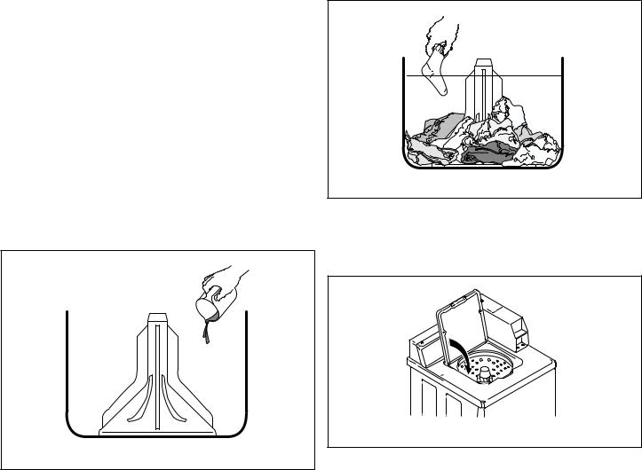
Add Detergent
1.Pour measured amount of detergent into washtub. Refer to package directions.
2.NEVER POUR UNDILUTED BLEACH DIRECTLY ON LAUNDRY. Follow package directions when using bleach.
W395I_SVG
Figure 20
Load Laundry
1.Load dry clothes loosely into washtub – DO NOT overload! (6.3 kg [14 lbs.] maximum dry clothes load)
2.When washing large items such as shag rugs and bedspreads, add several small items to balance wash load.
W392I_SVG
Figure 21
Close Lid
Washer will not operate with lid open.
TLW2202N_SVG
Figure 22
Set Wash Temperature and Fabric/Cycle Selector
One Speed Washers
NOTE: Wash temperature and cycle settings may be changed any time before first wash fill is complete.
Set wash temperature/cycle at either *HOT/NORMAL, *WARM/ PERM PRESS, *COLD/SPECIAL, or HOT/NORMAL, WARM/ PERM PRESS, COLD/SPECIAL.
Settings with asterisk (*) are Energy Saving Cycles.
© Copyright, Alliance Laundry Systems LLC - |
20 |
Part No. 202630R2 |
DO NOT COPY or TRANSMIT |
|
|
Loading...