


UTF75N
Table of contents
 Loading...
Installation/Operation/Maintenance
Tumble Dryers
50 Pound (25 Kilogram) Capacity
75 Pound (34 Kilogram) Capacity
Starting Serial No. 0904004427
Refer to Page 9 for Model Identification
TMB1277C_SVG
Original Instructions
Keep These Instructions for Future Reference.
(If this machine changes ownership, this manual must accompany machine.)
www.alliancelaundry.com
Part No: 70457901ENR16
July 2017

Installation must conform with local codes or, in the absence of local codes, with:
In the U.S.A., installation must conform to the latest edition of the American National Standard Z223.1/ NFPA 54 “National Fuel Gas
Code” and Standard ANSI/NFPA 70 “National Electric Code.”
In Canada, installation must comply with Standards CAN/CSA-B149.1 or Natural Gas and Propane Installation Code and CSA C22.1,
latest edition, Canadian Electric Code, Part I.
In Australia and New Zealand, installation must comply with the Gas Installations Standard AS/NZS 5601 Part 1: General Installa-
tions.
WARNING
FOR YOUR SAFETY, the information in this manual must be followed to minimize the risk of fire or explosion or
to prevent property damage, personal injury or death.
W033
WARNING
• Do not store or use gasoline or other flammable vapors and liquids in the vicinity of this or any other appli-
ance.
• WHAT TO DO IF YOU SMELL GAS:
• Do not try to light any appliance.
• Do not touch any electrical switch; do not use any phone in your building.
• Clear the room, building or area of all occupants.
• Immediately call your gas supplier from a neighbor’s phone. Follow the gas supplier’s instructions.
• If you cannot reach your gas supplier, call the fire department.
• Installation and service must be performed by a qualified installer, service agency or the gas supplier.
W052
IMPORTANT: Information must be obtained from a local gas supplier on instructions to be followed if the user
smells gas. These instructions must be posted in a prominent location. Step-by-step instructions of the above
safety information must be posted in a prominent location near the tumble dryer for customer use.
IMPORTANT: The installer must fully test the tumble dryer after installation and demonstrate to the owner how to
operate the machine.
WARNING
To reduce the risk of electric shock, fire, explosion, serious injury or death:
• Disconnect electric power to the tumble dryer before servicing.
• Close gas shut-off valve to gas tumble dryer before servicing.
• Close steam valve to steam tumble dryer before servicing.
• Never start the tumble dryer with any guards/panels removed.
• Whenever ground wires are removed during servicing, these ground wires must be reconnected to ensure
that the tumble dryer is properly grounded.
W002R1
©
Copyright, Alliance Laundry Systems LLC -
DO NOT COPY or TRANSMIT
3 Part No: 70457901ENR16

WARNING
• Installation of unit must be performed by a qualified installer.
• Install tumble dryer according to manufacturer’s instructions and local codes.
• DO NOT install a tumble dryer with flexible plastic venting materials. If flexible metal (foil type) duct is instal-
led, it must be of a specific type identified by the appliance manufacturer as suitable for use with tumble
dryer. Refer to section on connecting exhaust system. Flexible venting materials are known to collapse, be
easily crushed, and trap lint. These conditions will obstruct tumble dryer airflow and increase the risk of
fire.
W752R1
The following information applies to the state of Massachusetts, USA.
• This appliance can only be installed by a Massachusetts licensed plumber or gas fitter.
• This appliance must be installed with a 36 inch [91 cm] long flexible gas connector.
• A “T-Handle” type gas shut-off valve must be installed in the gas supply line to this appliance.
• This appliance must not be installed in a bedroom or bathroom.
©
Copyright, Alliance Laundry Systems LLC -
DO NOT COPY or TRANSMIT
4 Part No: 70457901ENR16

Table of Contents
Introduction........................................................................................... 9
Model Identification........................................................................................9
Contact Information...................................................................................... 12
Manufacturing Date ..................................................................................... 12
................................................................................................................12
Safety Information................................................................................13
Explanation of Safety Messages..................................................................... 13
Important Safety Instructions......................................................................... 13
Specifications and Dimensions.............................................................. 15
Specifications and Dimensions ...................................................................... 15
Cabinet Dimensions...................................................................................... 17
Exhaust Outlet Locations...............................................................................18
Gas Connection Locations............................................................................. 19
Electrical Connection Locations..................................................................... 20
Steam Connection Locations..........................................................................21
Installation........................................................................................... 22
Pre-Installation Inspection............................................................................. 22
Location Requirements..................................................................................22
Position and Level the Tumble Dryer..............................................................23
Fire Suppression System (Optional Equipment)............................................... 24
Check Local Codes and Permits..................................................................24
Water Requirements...................................................................................24
Water Connections.....................................................................................24
Electrical Requirements............................................................................. 25
Auxiliary Alarm........................................................................................ 25
Bolt-On Angle Option................................................................................... 26
To Reverse the Loading Door ........................................................................ 27
Before Placing Tumble Dryer into Service.......................................................29
Required for CE Models Only.................................................................... 31
Installing CE Gas Drying Tumble Dryer..........................................................31
General Information.................................................................................. 31
CE Orifices ..............................................................................................32
Properties of CE Gases.............................................................................. 33
Changing Gas Configuration...................................................................... 34
Specific Conversion Procedures..................................................................35
Exhaust Requirements..........................................................................37
©
Copyright 2017, Alliance Laundry Systems LLC
All rights reserved. No part of the contents of this book may be reproduced or transmitted in any form or by any means without the expressed
written consent of the publisher.
©
Copyright, Alliance Laundry Systems LLC -
DO NOT COPY or TRANSMIT
5 Part No: 70457901ENR16

Exhaust Requirements...................................................................................37
Layout......................................................................................................... 37
Make-Up Air................................................................................................37
Venting........................................................................................................ 37
Individual Venting..................................................................................... 39
Manifold Venting...................................................................................... 39
Gas Requirements.................................................................................42
Gas Requirements.........................................................................................42
Gas Supply Pipe Sizing and Looping.............................................................. 44
Low Pressure Gas Pipe Sizes......................................................................45
High Pressure Gas Pipe Sizes..................................................................... 47
High Altitude Burner Orifice Sizing ...............................................................48
Electrical Requirements........................................................................52
Electrical Requirements.................................................................................52
Wiring Diagram............................................................................................52
Wiring for Central Pay...................................................................................52
Grounding Instructions..................................................................................54
For CE Models Only..................................................................................54
Service/Ground Location........................................................................... 55
To Connect Electrical Service To The Tumble Dryer........................................ 56
Jumper Configuration Instructions..................................................................56
Ferrite Ring Installation ................................................................................57
Electrical Specifications ............................................................................... 59
Steam Requirements.............................................................................62
Steam Requirements......................................................................................62
Piping Recommendations.............................................................................. 64
Installing Steam Trap and Making Condensate Return Connections...................64
Thermal Oil Prep.......................................................................................... 64
Single Drop Timer................................................................................ 65
Power-Up Mode........................................................................................... 65
Ready Mode.................................................................................................65
Start Mode................................................................................................... 65
Run Mode.................................................................................................... 65
Door Open Mode.......................................................................................... 65
End of Cycle Mode....................................................................................... 65
Setting Dry Time Dipswitches........................................................................65
Models Through Serial No. 0908xxxxx....................................................... 65
Models Starting Serial No. 0909xxxxx........................................................ 65
Resetting Cycle Time to Zero.........................................................................65
Dipswitch Settings........................................................................................ 66
Topoffs........................................................................................................ 69
Temperature Selector Switch..........................................................................69
To Program a Short Test Cycle....................................................................... 69
Error Codes..................................................................................................69
©
Copyright, Alliance Laundry Systems LLC -
DO NOT COPY or TRANSMIT
6 Part No: 70457901ENR16

Operating Instructions..........................................................................70
Operating Instructions................................................................................... 70
Emergency Stop Button On CE Models.......................................................... 70
Operating Instructions................................................................................... 70
Reversing Operation......................................................................................71
Control Instructions.......................................................................................71
Dual Digital Timer Control.........................................................................71
Electronic OPL Micro Control....................................................................73
Single Drop Control...................................................................................74
MDC Coin and Card Control......................................................................74
Quantum Control ......................................................................................75
Galaxy 600 Control .................................................................................. 76
LED OPL Control .................................................................................... 77
UniLinc Control ....................................................................................... 78
DX4 Coin Control..................................................................................... 79
DX4 OPL Control..................................................................................... 80
Diagnostic Microprocessor Control ............................................................ 80
DMP OPL Models.....................................................................................82
DMP Coin................................................................................................ 84
Ignition Control Operation and Troubleshooting for Models Starting 3/11/13..... 86
Internal Control Failure..............................................................................86
Troubleshooting........................................................................................ 86
Proper Electrode Location..........................................................................87
Flame Current Measurement.......................................................................87
Ignition Control Operation for Non-CE Models Through 3/10/13...................... 87
Ignition Control Operation for CE Models Through 3/10/13............................. 88
System Tests............................................................................................. 89
Diagnostic LED (DGN LED)/Error Codes...................................................89
Adjustments......................................................................................... 90
Adjustments................................................................................................. 90
Gas Burner Air Shutter.................................................................................. 90
Airflow Switch ............................................................................................ 91
Loading Door Switch.................................................................................... 91
Loading Door Catch .....................................................................................92
Drive Belt - Nonreversing Models.................................................................. 92
Drive Belt - Reversing Models....................................................................... 92
Maintenance......................................................................................... 94
Daily........................................................................................................... 94
Monthly....................................................................................................... 94
Quarterly......................................................................................................94
Bi-Annually................................................................................................. 95
Annually...................................................................................................... 95
Fire Suppression System (Optional Equipment) Maintenance Test.....................95
Before You Call for Service................................................................... 97
©
Copyright, Alliance Laundry Systems LLC -
DO NOT COPY or TRANSMIT
7 Part No: 70457901ENR16

Removing Tumble Dryer from Service.................................................. 98
Disposal of Unit.................................................................................... 99
China Restriction of hazardous substances (RoHS)............................. 100
©
Copyright, Alliance Laundry Systems LLC -
DO NOT COPY or TRANSMIT
8 Part No: 70457901ENR16

Introduction
Model Identification
Information in this manual is applicable to these models. Refer
to the machine serial plate for the model number.
Gas Steam/Thermal Oil Electric
050 Series
(25 Kg)
BA050L
BA050N
BH050L
BH050N
BK050N
BT050D
BT050L
BT050N
BU050L
BU050N
CA050L
CA050N
CK050N
CT050L
CT050N
CU050L
CU050N
HA050L
HA050N
HH050L
HH050N
HK050N
HT050D
HT050L
HT050N
HU050L
HU050N
IT050L
IT050N
LA050L
LA050N
LK050N
LT050L
LT050N
LU050L
LU050N
MT050L
MT050N
NH050L
NH050N
NT050L
NT050N
NU050L
NU050N
PA050L
PA050N
PH050L
PH050N
PK050N
PT050L
PT050N
PU050L
PU050N
SA050L
SA050N
SH050L
SH050N
SK050N
ST050D
ST050L
ST050N
SU050L
SU050N
UA050L
UA050N
UH050L
UH050N
UK050N
UT050L
UT050N
UU050L
UU050N
YT050L
YT050N
YU050L
YU050N
BH050S
BT050S
BT050T
BU050S
BU050T
CT050S
CT050T
CU050S
CU050T
HH050S
HT050S
HT050T
HU050S
HU050T
IT050S
IT050T
LT050S
LT050T
LU050S
LU050T
MT050S
MT050T
NH050S
NT050S
NU050S
PH050S
PT050S
PT050T
PU050S
PU050T
SH050S
ST050S
ST050T
SU050S
SU050T
UH050S
UT050S
UT050T
UU050S
UU050T
YT050S
YT050T
YU050S
YU050T
BH050E
BT050E
BU050E
CT050E
CU050E
HH050E
HT050E
HU050E
IT050E
LT050E
LU050E
MT050E
NH050E
NT050E
NU050E
PH050E
PT050E
PU050E
SH050E
ST050E
SU050E
UH050E
UT050E
UU050E
YT050E
YU050E
Table continues...
Introduction
©
Copyright, Alliance Laundry Systems LLC -
DO NOT COPY or TRANSMIT
9 Part No: 70457901ENR16

Gas Steam/Thermal Oil Electric
075 Series
(34 Kg)
BA075L
BA075N
BH075L
BH075N
BH075R
BK075N
BK075R
BT075D
BT075L
BT075N
BT075R
BU075L
BU075N
BU075R
CA075L
CA075N
CK075N
CK075R
CT075L
CT075N
CT075R
CU075L
CU075N
CU075R
HA075L
HA075N
HH075L
HH075N
HH075R
HK075N
HK075R
HT075D
HT075L
HT075N
HT075R
HU075L
HU075N
HU075R
IT075L
IT075N
IT075R
LA075L
LA075N
LK075N
LT075L
LT075N
LU075L
LU075N
MT075L
MT075N
MT075R
NH075L
NH075N
NT075L
NT075N
NU075L
NU075N
PA075L
PA075N
PH075L
PH075N
PK075N
PT075L
PT075N
PU075L
PU075N
SA075L
SA075N
SH075L
SH075N
SH075R
SK075N
SK075R
ST075D
ST075L
ST075N
ST075R
STF75L
STF75N
SU075L
SU075N
SU075R
UA075L
UA075N
UH075L
UH075N
UH075R
UK075N
UK075R
UT075L
UT075N
UT075R
UTF75L
UTF75N
UU075L
UU075N
UU075R
YT075L
YT075N
YU075L
YU075N
BH075S
BT075S
BT075T
BU075S
BU075T
CT075S
CT075T
CU075S
CU075T
HH075S
HT075S
HT075T
HU075S
HU075T
IT075S
IT075T
LT075S
LT075T
LU075S
LU075T
MT075S
MT075T
NH075S
NT075S
NU075S
PH075S
PT075S
PT075T
PU075S
PU075T
SH075S
ST075S
ST075T
SU075S
SU075T
UH075S
UT075S
UT075T
UU075S
UU075T
YT075S
YT075T
YU075S
YU075T
BH075E
BH075F
BT075E
BT075F
BU075E
BU075F
CT075E
CT075F
CU075E
CU075F
HH075E
HH075F
HT075E
HT075F
HU075E
HU075F
IT075E
IT075F
LT075E
LU075E
MT075E
MT075F
NH075E
NT075E
NU075E
PH075E
PT075E
PU075E
SH075E
SH075F
ST075E
ST075F
SU075E
SU075F
UB075E
UH075E
UH075F
UT075E
UT075F
UU075E
UU075F
YT075E
YU075E
Explanation of digit in 6th position of model number:
Introduction
©
Copyright, Alliance Laundry Systems LLC -
DO NOT COPY or TRANSMIT
10 Part No: 70457901ENR16
D = Liquid Petroleum (L.P.) Gas, Japan
E = Electric
F = Reduced Electric (Eco Line)
L = L.P. Gas
N = Natural Gas
R = Reduced Gas, Natural Gas (Eco Line)
S = Steam
T = Thermal Oil
Includes models with the following control suffixes:
3B – reversing DX4 vended
3K – reversing DX4 prep for central pay
3L – DX4 prep for central pay
3O – DX4 OPL
3V – DX4 vended
3W – reversing DX4 prep for coin
3X – DX4 prep for coin
BB – reversing basic electronic, coin
BC – basic electronic, coin
BG – basic electronic, OPL mode
BK – reversing basic electronic, prep for
central pay
BL – basic electronic, prep for central
pay
BW – reversing basic electronic, prep for
coin
BX – basic electronic, prep for coin
BY – basic electronic, prep for card
BZ – reversing basic electronic, prep for
card
DO – DMP OPL
EO – LED OPL
KB – reversing single coin
KC – single coin
KK – reversing prep for central pay
KL – prep for central pay
KW – reversing prep for coin
KX – prep for coin
KY – prep for card
KZ – reversing prep for card
LB – reversing network adaptable coin
LC – network adaptable coin
LK – reversing network adaptable, prep
for central pay
LL – network adaptable, prep for central
pay
LW – reversing network adaptable, prep
for coin
LX – network adaptable, prep for coin
LY – network adaptable, prep for card
LZ – reversing network adaptable, prep
for card
OM – OPL micro
QT – dual digital timer
R3 – reversing DX4 OPL
RD – reversing DMP OPL
RE – reversing LED OPL
RM – reversing OPL micro
RQ – reversing dual digital timer
RU – reversing UniLinc OPL
SD – single drop
SX – single drop, prep for coin
UO – UniLinc OPL
WB – reversing network ready coin
WC – network ready coin
WK – reversing network ready, prep for
central pay
WL – network ready, prep for central pay
WW – reversing network ready, prep for
coin
WX – network ready, prep for coin
WY – network ready, prep for card
WZ – reversing network ready, prep for
card
ZB – reversing network ready, single
coin
ZC – network ready, single coin
ZK – reversing network ready, prep for
central pay
ZL – network ready, prep for central pay
ZW – reversing network ready, prep for
coin
ZX – network ready, prep for coin
ZY – network ready, prep for card
ZZ – reversing network ready, prep for
card
Introduction
©
Copyright, Alliance Laundry Systems LLC -
DO NOT COPY or TRANSMIT
11 Part No: 70457901ENR16
Contact Information
If service is required, contact the nearest Factory Authorized
Service Center.
If you are unable to locate an authorized service center or are un-
satisfied with the service performed on your unit, contact:
Alliance Laundry Systems
Shepard Street
P.O. Box 990
Ripon, WI 54971-0990
U.S.A.
www.alliancelaundry.com
Phone: +1 (920) 748-3121
When calling or writing about your unit, PLEASE GIVE THE
MODEL AND SERIAL NUMBERS. The model and serial num-
bers are located on the serial plate. The serial plate will be in the
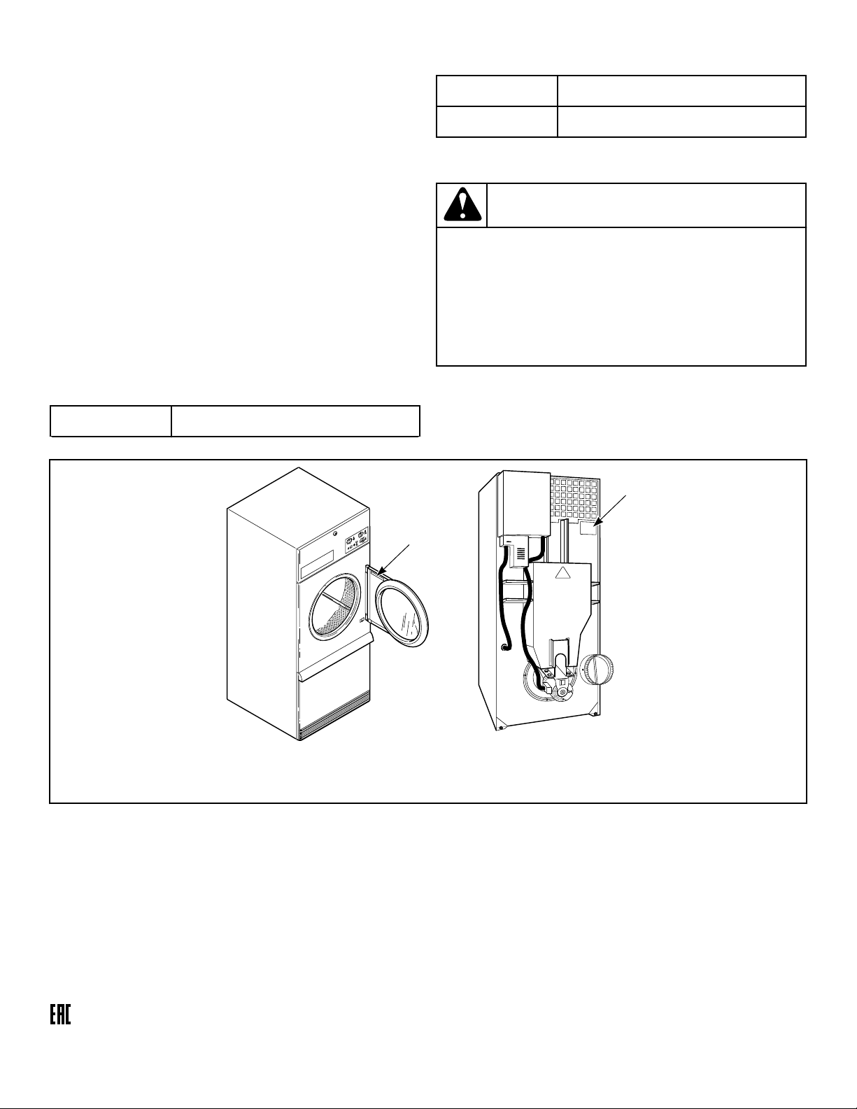
location shown in Figure 1 .
Date Purchased
Table continues...
Model Number
Serial Number
Please include a copy of your bill of sale and any service receipts
you have.
WARNING
To reduce the risk of serious injury or death, DO NOT
repair or replace any part of the unit or attempt any
servicing unless specifically recommended in the
user-maintenance instructions or in published user-
repair instructions that you understand and have the
skills to carry out.
W329
If replacement parts are required, contact the source from where
you purchased your unit or call +1 (920) 748-3950 for the name
and address of the nearest authorized parts distributor.
TMB2235N_SVG
1
1
1. Serial Plate
Figure 1
Manufacturing Date
The manufacturing date for your unit can be found on the serial
number. The first two digits indicate the year. The third and
fourth digits indicate the month. For example, a unit with serial
number 1505000001 was manufactured in May 2015.
Introduction
©
Copyright, Alliance Laundry Systems LLC -
DO NOT COPY or TRANSMIT
12 Part No: 70457901ENR16
Safety Information
Explanation of Safety Messages
Precautionary statements (“DANGER,” “WARNING,” and
“CAUTION”), followed by specific instructions, are found in this
manual and on machine decals. These precautions are intended
for the personal safety of the operator, user, servicer, and those
maintaining the machine.
DANGER
Indicates an imminently hazardous situation that, if
not avoided, will cause severe personal injury or
death.
WARNING
Indicates a hazardous situation that, if not avoided,
could cause severe personal injury or death.
CAUTION
Indicates a hazardous situation that, if not avoided,
may cause minor or moderate personal injury or
property damage.
Additional precautionary statements (“IMPORTANT” and
“NOTE”) are followed by specific instructions.
IMPORTANT: The word “IMPORTANT” is used to in-
form the reader of specific procedures where minor
machine damage will occur if the procedure is not fol-
lowed.
NOTE: The word “NOTE” is used to communicate in-
stallation, operation, maintenance or servicing informa-
tion that is important but not hazard related.
Important Safety Instructions
WARNING
To reduce the risk of fire, electric shock, serious in-
jury or death to persons when using your tumble
dryer, follow these basic precautions.
W776R1
Save These Instructions
• Read all instructions before using the tumble dryer.
• Install the tumble dryer according to the INSTALLATION in-
structions. Refer to the EARTHING (grounding) instructions
for the proper earthing (grounding) of the tumble dryer. All
connections for electrical power, earthing (grounding) and gas
supply must comply with local codes and be made by licensed
personnel when required. It is recommended that the machine
be installed by qualified technicians.
• Do not install or store the tumble dryer where it will be ex-
posed to water and/or weather. The tumble dryer cannot be
used in a closed room where the air supply is insufficient. If
necessary, ventilation grids must be installed in the doors or
the windows.
• This tumble dryer must not be activated without lint screen
filter.
• When you perceive a gas odor, immediately shut off the gas
supply and ventilate the room. Do not power on electrical ap-
pliances and do not pull electrical switches. Do not use
matches or lighters. Do not use a phone in the building. Warn
the installer, and if so desired, the gas company, as soon as
possible.
• To avoid fire and explosion, keep surrounding areas free of
flammable and combustible products. Regularly clean the cyl-
inder and exhaust tube should be cleaned periodically by
competent maintenance personnel. Daily remove debris from
lint screen filter and inside of filter compartment.
• Do not use or store flammable materials near this appliance.
• Do not place into tumble dryer articles that have been previ-
ously cleaned in, washed in, soaked in or spotted with gaso-
line or machine oils, vegetable or cooking oils, cleaning wax-
es or chemicals, dry-cleaning solvents, thinner or other flam-
mable or explosive substances as they give off vapors that
could ignite, explode or cause fabric to catch on fire by itself.
• Do not spray aerosols in the vicinity of this appliance while it
is in operation.
• Items such as foam rubber (latex foam), shower caps, water-
proof textiles, rubber backed articles and clothes or pillows
filled with foam rubber pads should not be dried in the tumble
dryer. Do not use the appliance to dry materials with a low
melting temperature (PVC, rubber, etc.).
• Do not tumble fiberglass curtains and draperies unless the la-
bel says it can be done. If they are dried, wipe out the cylinder
with a damp cloth to remove particles of fiberglass.
• Do not allow children to play on or in the washer. Close su-
pervision of children is necessary when the washer is used
near children. This appliance is not intended for use by per-
sons (including children) with reduced physical, sensory or
mental capabilities, or lack of experience and knowledge, un-
less they have been given supervision or instruction concern-
ing the use of the appliance by a person responsible for their
safety. This is a safety rule for all appliances.
• Cleaning and user maintenance shall not be made by children
without supervision.
Safety Information
©
Copyright, Alliance Laundry Systems LLC -
DO NOT COPY or TRANSMIT
13 Part No: 70457901ENR16

• Children less than three years should be kept away unless
continuously supervised.
• Do not reach into the tumble dryer if the cylinder is revolving.
• Use tumble dryer only for its intended purpose, drying fab-
rics. Always follow the fabric care instructions supplied by
the textile manufacturer and only use the dryer to dry textiles
that have been washed in water. Only insert spin-dried linen
in the dryer to avoid damage to dryer.
• Always read and follow manufacturer’s instructions on pack-
ages of laundry and cleaning aids. Follow all warnings or pre-
cautions. To reduce the risk of poisoning or chemical burns,
keep them out of the reach of children at all times (preferably
in a locked cabinet).
• Do not use fabric softeners or products to eliminate static un-
less recommended by the manufacturer of the fabric softener
or product.
• Remove laundry immediately after tumble dryer stops.
• DO NOT operate the tumble dryer if it is smoking, grinding
or has missing or broken parts or removed guards or panels.
DO NOT tamper with the controls or bypass any safety devi-
ces.
• Tumble dryer will not operate with the loading door open. DO
NOT bypass the door safety switch to permit the tumble dryer
to operate with the door open. The tumble dryer will stop ro-
tating when the door is opened. Do not use the tumble dryer if
it does not stop rotating when the door is opened or starts
tumbling without pressing the START mechanism. Remove
the tumble dryer from use and call for service.
• Tumble dryer will not operate with lint panel open. DO NOT
bypass lint panel door safety switch to permit the tumble dry-
er to operate with the lint panel door open.
• Do not alter this tumble dryer from factory construction ex-
cept as otherwise described in the technical instructions.
• Always clean the lint filter daily. Keep area around the ex-
haust opening and adjacent surrounding area free from the ac-
cumulation of lint, dust and dirt. The interior of the tumble
dryer and the exhaust duct should be cleaned periodically by
qualified service personnel.
• Solvent vapors from dry-cleaning machines create acids when
drawn through the heater of the drying unit. These acids are
corrosive to the tumble dryer as well as the laundry load being
dried. Be sure make-up air is free of solvent vapors.
• At the end of each working day, close off all main supplies of
gas, steam and electricity.
IMPORTANT: For fire suppression equipped tumble
dryers, electricity and water should NOT be turned
off.
• Do not repair or replace any part of the tumble dryer, or at-
tempt any servicing unless specifically recommended in the
user-maintenance instructions or in published user-repair in-
structions that the user understands and has the skills to carry
out. ALWAYS disconnect and lockout the electrical power to
the tumble dryer before servicing. Disconnect power by shut-
ting off appropriate breaker or fuse.
• Activation of the emergency stop switch stops all tumble dry-
er control circuit functions, but DOES NOT remove all elec-
trical power from tumble dryer.
• Exhaust ductwork should be examined and cleaned annually
after installation.
• Before the tumble dryer is removed from service or discarded,
remove the door to the drying compartment and the door to
the lint compartment.
• Failure to install, maintain, and/or operate this tumble dryer
according to the manufacturer’s instructions may result in
conditions which can produce bodily injury and/or property
damage.
NOTE: The WARNINGS and IMPORTANT SAFETY IN-
STRUCTIONS appearing in this manual are not meant
to cover all possible conditions and situations that may
occur. Observe and be aware of other labels and pre-
cautions that are located on the machine. They are in-
tended to provide instruction for safe use of the ma-
chine. Common sense, caution and care must be exer-
cised when installing, maintaining, or operating the
tumble dryer.
Always contact your dealer, distributor, service agent or the man-
ufacturer about any problems or conditions you do not under-
stand.
Safety Information
©
Copyright, Alliance Laundry Systems LLC -
DO NOT COPY or TRANSMIT
14 Part No: 70457901ENR16

Specifications and Dimensions
Specifications and Dimensions
Refer to machine serial plate for additional specifications.
Specifications 050 Series 075 Series F75
Heat dissipation of surface area exposed
to conditioned air: Btu/ft
2
[Joules/m
2
]
60 [681,392] 60 [681,392] 60 [681,392]
Noise level measured during operation
at operator position of 3.3 feet [1 me-
ter ] in front of machine and 5.2 feet
[1.6 meters ] from floor (approximate)
60 dBA 65 dBA 67 dBA
Net Weight (approximate):
Pounds [Kilograms ]
545 [247] 615 [279] 710 [322]
Standard Packaging Weight: Pounds
[Kilograms]
602 [273] 677 [307] 772 [350]
Standard Packaging Shipping Dimen-
sions: Inches [Millimeters ]
41.5 x 52.1 x 81
[1054 x 1323 x
2057]
41.5 x 56.4 x 81 [1054 x 1433 x 2057] 41.5 x 56.4 x 81
[1054 x 1433 x
2057]
Slat Crate Packaging Weight: Pounds
[Kilograms]
669 [303] 742 [337] 837 [380]
Slat Crate Shipping Dimensions: Inches
[Millimeters ]
44.5 x 55 x 87.75
[1130 x 1397 x
2229]
44.5 x 59.25 x 87.75 [1130 x 1505 x
2229]
44.5 x 59.25 x 87.75
[1130 x 1505 x
2229]
Cylinder Size:
Inches [Millimeters ]
37 x 30 [940 x 762] 37 x 36 [940 x 914 ] 37 x 36 [940 x 914]
Cylinder Capacity (dry weight):
Pounds [Kilograms ]
50 [25] 75 [34] 75 [34]
Air Outlet Diameter:
Inches [Millimeters]
8 [203] 8 [203] 10 [254]
Maximum Static Back Pressure:
W.C.I. [Millibar, kPa]
0.5 [1.3, 0.13] 0.5 [1.3, 0.13] 0.5 [1.3, 0.13]
Maximum Airflow:
C.F.M. [L/sec]
750 [354] Classic Line
Gas/Steam
60 Hz 920 [434]
50 Hz 750 [354]
Electric 750 [354]
Eco Line
60 Hz 750 [354]
50 Hz 625 [295]
1100 [519]
Table continues...
Specifications and Dimensions
©
Copyright, Alliance Laundry Systems LLC -
DO NOT COPY or TRANSMIT
15 Part No: 70457901ENR16
Specifications 050 Series 075 Series F75
Motor: Horsepower [kW]
Nonreversing 1/2 [0.373] 3/4 [0.560] Not Applicable
Reversing Fan 1/3 [0.249] 1/3 [0.249] 1 [0.746]
Reversing Cylinder 1/3 [0.249] 1/3 [0.249] 1/3 [0.249]
Gas Models
Gas Connection 1/2 in. NPT 1/2 in. NPT 3/4 in. NPT
Gas Burner Rating:
Btu/hr. [Mj/hr., kW]
130,000 [137, 38.1] Classic Line
165,000 [174,
48.359]
Eco Line
60 Hz 130,000
[137.2, 38.1]
50 Hz 110,000
[116.1, 32.2]
225,000 [237, 65.94]
Electric Models
Heating Element Rating:
Kilowatts
21 kW (240 V/50
Hz)
30 kW (other vol-
tages)
Classic Line - 30 kW
Eco Line - 21 kW
Not Applicable
Steam Models
Steam Connection 3/4 in. NPT 3/4 in. NPT Not Applicable
Steam Coil Rating at 100 psig:
Btu/hr. [kg/hr.]
(recommended operating pressure
80-100 psig)
177,500 [83.14] 210,300 [98.5] Not Applicable
NOTE: All machines are shipped with extra nipple to
convert to metric thread (from Standard).
Specifications and Dimensions
©
Copyright, Alliance Laundry Systems LLC -
DO NOT COPY or TRANSMIT
16 Part No: 70457901ENR16
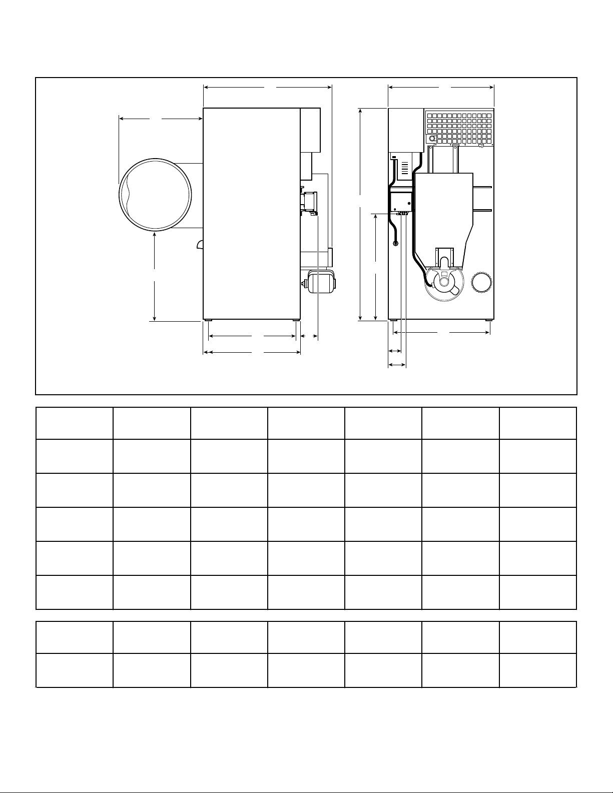
Cabinet Dimensions
TMB2422N_SVG
E
I
H
G
F
D
K
L
J
C
B
A
Models A B C D E* F
050 Series Gas
and Electric
30.75 in. [781
mm]
33.87 in. [860
mm]
48.25 in. [1226
mm]
76.625 in.
[1946 mm]
36 in. [914
mm]
38.625 in. [981
mm]
050 Series
Steam
30.75 in. [781
mm]
33.87 in. [860
mm]
48.25 in. [1226
mm]
76.625 in.
[1946 mm]
36 in. [914
mm]
38.625 in. [981
mm]
075 Series Gas
and Electric
30.75 in. [781
mm]
33.87 in. [860
mm]
54.25 in. [1378
mm]
76.625 in.
[1946 mm]
36 in. [914
mm]
38.625 in. [981
mm]
075 Series
Steam
30.75 in. [781
mm]
33.87 in. [860
mm]
54.25 in. [1378
mm]
76.625 in.
[1946 mm]
36 in. [914
mm]
38.625 in. [981
mm]
F75 Gas 30.75 in. [781
mm]
33.87 in. [860
mm]
53 in. [1346
mm]
76.625 in.
[1946 mm]
36 in. [914
mm]
38.625 in. [981
mm]
Models G H* I* J* K L
050 Series Gas
and Electric
33 in. [838
mm]
7.1 in. [180
mm]
5.5 in. [140
mm]
6.53 in. [166
mm ]
29.5 in. [749
mm]
33.24 in. [844
mm]
Table continues...
Specifications and Dimensions
©
Copyright, Alliance Laundry Systems LLC -
DO NOT COPY or TRANSMIT
17 Part No: 70457901ENR16
Models G H* I* J* K L
050 Series
Steam
33 in. [838
mm]
7.1 in. [180
mm]
5.5 in. [140
mm]
6.53 in. [166
mm ]
29.5 in. [749
mm]
33.24 in. [844
mm]
075 Series Gas
and Electric
33 in. [838
mm]
7.1 in. [180
mm]
5.5 in. [140
mm]
6.53 in. [166
mm ]
35.5 in. [902
mm]
39.22 in. [996
mm]
075 Series
Steam
33 in. [838
mm]
7.1 in. [180
mm]
5.5 in. [140
mm]
6.53 in. [166
mm ]
35.5 in. [902
mm]
39.22 in. [996
mm]
F75 Gas 33 in. [838
mm]
7.1 in. [180
mm]
5.5 in. [140
mm]
6.53 in. [166
mm ]
35.5 in. [902
mm]
39.22 in. [996
mm]
* Fire suppression system optional - may not be on machine.
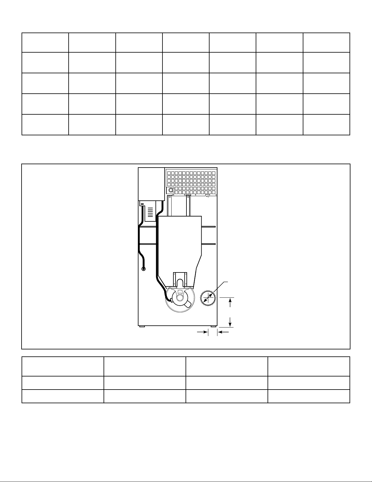
Exhaust Outlet Locations
TMB2238N_SVG
C
A
B
Models A B C
050/075 Series 5.375 in. [137 mm ] 8 in. [203 mm ] 13.375 in. [340 mm ]
F75 6.5 in. [165 mm] 10 in. [254 mm ] 6.5 in. [165 mm]
Specifications and Dimensions
©
Copyright, Alliance Laundry Systems LLC -
DO NOT COPY or TRANSMIT
18 Part No: 70457901ENR16
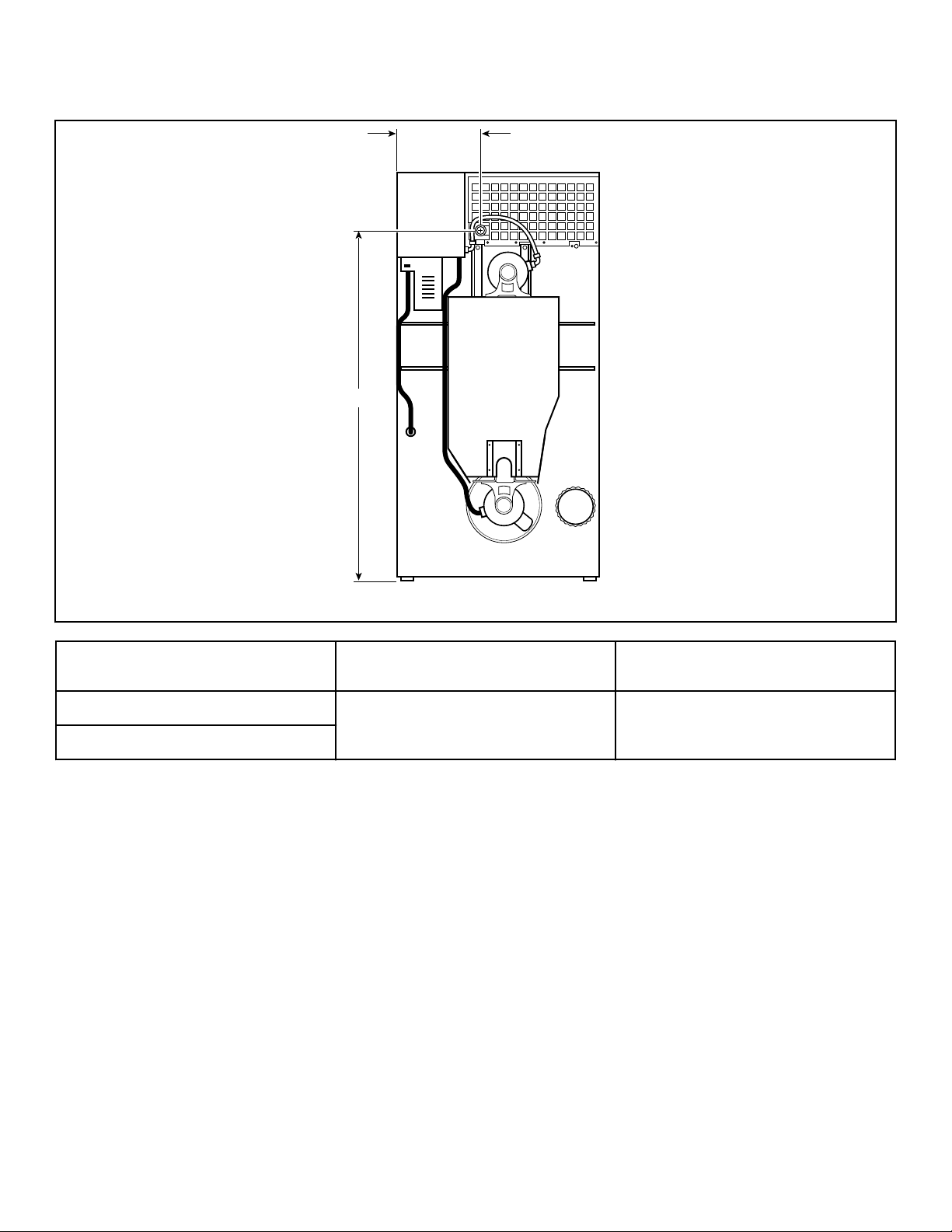
Gas Connection Locations
TMB2239N_SVG
B
A
Diameter A B
050/075 – 1/2 in. NPT 14.75 in. [375 mm] 65.75 in. [1670 mm]
F75 – 3/4 in. NPT
Specifications and Dimensions
©
Copyright, Alliance Laundry Systems LLC -
DO NOT COPY or TRANSMIT
19 Part No: 70457901ENR16
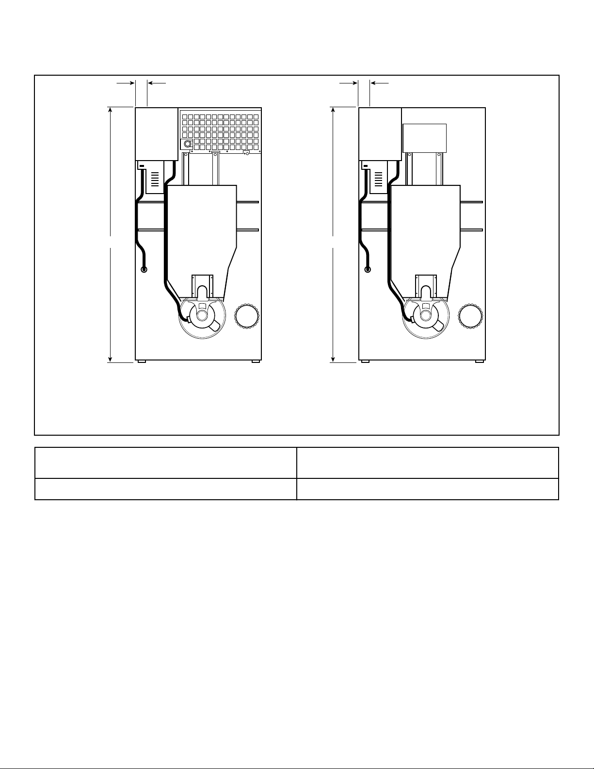
Electrical Connection Locations
TMB2240N_SVG
B
A
1 2
B
A
1. Gas and Steam
2. Electric
A B
3.25 in. [83 mm] 75.5 in. [1918 mm]
NOTE: These figures are approximate dimensions only.
Specifications and Dimensions
©
Copyright, Alliance Laundry Systems LLC -
DO NOT COPY or TRANSMIT
20 Part No: 70457901ENR16
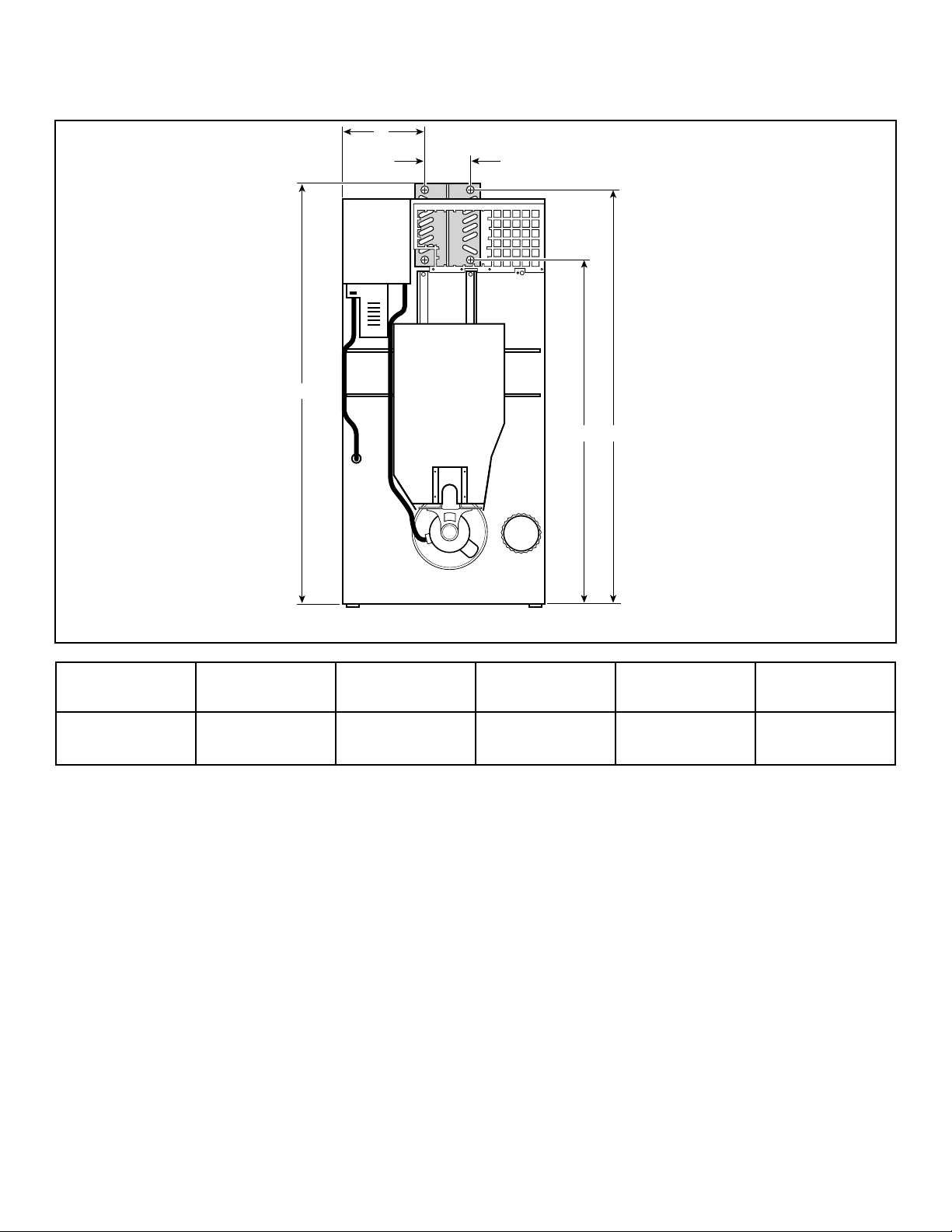
Steam Connection Locations
TMB2425N_SVG
B
A
C
D E
Diameter A
B
C D E
3/4 in. NPT 15.25 in. [387
mm]
79.23 in. [2013
mm]
7.5 in. [190 mm] 64.64 in. [1642
mm]
78.14 in. [1985
mm]
Specifications and Dimensions
©
Copyright, Alliance Laundry Systems LLC -
DO NOT COPY or TRANSMIT
21 Part No: 70457901ENR16
Installation
Pre-Installation Inspection
Upon delivery, visually inspect the crate, carton and parts for any
visible shipping damage. If the crate, carton, or cover is damaged
or signs of possible damage are evident, have the carrier note the
condition on the shipping papers before the shipping receipt is
signed, or advise the carrier of the condition as soon as it is dis-
covered.
Remove the crate and protective cover as soon as possible and
check the items listed on the packing list. Advise the carrier of
any damaged or missing articles as soon as possible. A written
claim should be filed with the carrier immediately if articles are
damaged or missing.
IMPORTANT: Remove the yellow shipping wire tie se-
curing the airflow switch.
IMPORTANT: Warranty is void unless tumble dryer is
installed according to instructions in this manual. In-
stallation should comply with minimum specifications
and requirements detailed in this manual and applica-
ble local gas fitting regulations, municipal building co-
des, water supply regulations, electrical wiring regula-
tions, and any other relevant statutory regulations. Due
to varied requirements, applicable local codes should
be thoroughly understood and all pre-installation work
arranged for accordingly.
Materials Required (Obtain Locally)
All Models Fused disconnect switch or circuit breaker
on 1 Phase models.
Circuit breaker on 3 Phase models.
Gas Models One gas shut-off valve for gas service line
to each tumble dryer.
Table continues...
Materials Required (Obtain Locally)
Steam Models One steam shut-off valve for steam service
line to be connected upstream of solenoid
steam valve.
Two steam shut-off valves for each conden-
sate return line.
Flexible steam hoses with a 125 psig
[pounds per square inch gauge] [862 kPa]
working pressure for connecting steam
coils. Refer to Figure 29 for sizing and con-
nection configurations.
Two steam traps for steam coil outlets to
condensate return line.
Optional – Two vacuum breakers for con-
densate return lines.
IMPORTANT: 3 Phase Only – Each tumble dryer must
be connected to its own individual branch circuit
breaker, not fuses, to avoid the possibility of “single
phasing” and causing premature failure of the mo-
tor(s).
Location Requirements
The tumble dryer must be installed on a level floor. Floor cover-
ing materials such as carpeting or tile should be removed.
To assure compliance, consult local building code requirements.
The tumble dryer must not be installed or stored in area where it
will be exposed to water and/or weather.
IMPORTANT: DO NOT block the airflow at the rear of
the tumble dryer with laundry or other articles. Doing
so would prevent adequate air supply to the combus-
tion chamber of the tumble dryer.
A typical tumble dryer enclosure is shown in Figure 2 .
IMPORTANT: Install tumble dryers with sufficient clear-
ance for servicing and operation, refer to Figure 2 .
WARNING
To reduce the risk of severe injury, clearance of tum-
ble dryer cabinet from combustible construction
must conform to the minimum clearances, and/or lo-
cal codes and ordinances.
W770R1
Installation
©
Copyright, Alliance Laundry Systems LLC -
DO NOT COPY or TRANSMIT
22 Part No: 70457901ENR16
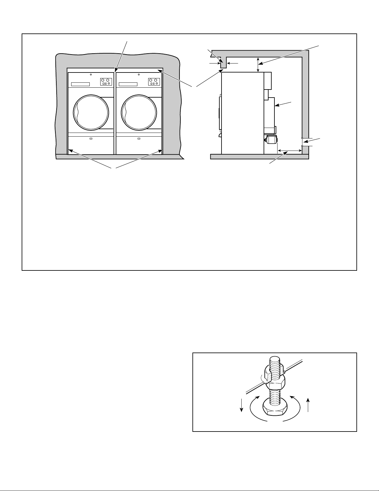
TMB2242N_SVG
4
3
1
6
8
7
2
5
NOTE: Shaded areas indicate adjacent structure.
1. 0 in. [0 mm] minimum, 0.5 in. [13 mm] recommended between machines for removal or installation
2. Allow 2-4 in. [51-100 mm] opening at top of machine to aid in removal or installation. A removable trim piece may be used to
conceal the opening; zero clearance allowed for trim.
3. 4 in. [100 mm] maximum header thickness
4. Minimum clearance permitted for remainder: 12 in. [305 mm]
5. Guard
6. Provision for make-up air
7. 24 in. [610 mm] minimum, 36 in. [914 mm] recommended for maintenance purposes
8. 0 in. [0 mm] minimum, 0.25 in. [6 mm] recommended for removal or installation purposes
Figure 2
Position and Level the Tumble Dryer
1. Remove lint panel door, and unscrew the four shipping bolts
(one at each corner).
2. Remove tumble dryer from pallet.
NOTE: DO NOT discard shipping bolts, they are
used as machine leveling legs.
3. Remove four nuts from the literature package, and screw one
fully on to each leveling leg.
4. Screw the four leveling legs (bolts) back into the level adjust-
ing fittings from the bottom.
5. Slide tumble dryer to its permanent location. Adjust the level-
ing legs until the unit is level, or no more than 0.13 inch [3.3
mm] higher in the front. Refer to Figure 3 . Tumble dryer
must not rock. Lock leveling legs with nuts previously instal-
led.
NOTE: The front of the tumble dryer should be
slightly higher than the rear (approximately 0.13
inch [3.3 mm]). This will prevent the clothes, while
tumbling, from wearing on the door glass gasket.
IMPORTANT: Keep tumble dryer as close to floor as
possible. The unit must rest firmly on floor so
weight of tumble dryer is evenly distributed.
T483I_SVG
Figure 3
Installation
©
Copyright, Alliance Laundry Systems LLC -
DO NOT COPY or TRANSMIT
23 Part No: 70457901ENR16
Fire Suppression System (Optional
Equipment)
WARNING
ELECTRICAL SHOCK HAZARD. Electrical shock can
result in death or serious injury. If the water dispens-
ing system is activated, do not attempt to operate
the tumble dryer. If the water dispensing system is
activated, have the tumble dryer inspected by a
qualified agency before operating the tumble dryer.
W879R1
IMPORTANT: Main supplies of electricity and water to
the tumble dryer should remain on at all times for the
fire suppression system to work.
Check Local Codes and Permits
Call your local water company or the proper municipal authority
for information regarding local codes.
IMPORTANT: It is your responsibility to have ALL
plumbing connections made by a qualified professio-
nal to assure that the plumbing is adequate and con-
forms to local, state, and federal regulations or codes.
IMPORTANT: It is the installation or owner’s responsi-
bility to confirm that the necessary or required water,
water pressure, pipe size, or connections are provided.
Manufacturer assumes no responsibility if the fire sup-
pression system is not connected, installed, or main-
tained properly.
Water Requirements
IMPORTANT: Water must be supplied to the fire sup-
pression system, or the fire suppression system will
not operate as intended.
To ensure the fire suppression system operates properly:
• Water supply requirements: 3/4 inch hose connections provid-
ing 15 gpm [57 lpm] minimum flow; Water pressure 20 psi
[138 kPa] minimum, 120 psi [827 kPa] maximum; water tem-
perature 40°F [4.5°C] minimum, 120°F [49°C] maximum
must be maintained at all times.
• Electric power to the tumble dryer must be provided at all
times.
• Perform preventative maintenance checks every month. Refer
to Operation/Maintenance Manual.
NOTE: Water pressure under 20 psi [138 kPa] will
cause low flow at water solenoid valve.
If the rear of the tumble dryer or the water supply is located in an
area where it will be exposed to cold/freezing temperatures, pro-
visions must be made to protect these water lines from freezing.
IMPORTANT: Temperature of the water supply must be
kept between 40°F and 120°F [4.5°C and 49°C]. If water
in the supply line or water solenoid valve freezes, the
fire suppression system will not operate.
IMPORTANT: If temperature sensors inside the tumble
dryer register a temperature below 40F° [4.5°C], the fire
suppression system control will lock out. This feature
protects against operation of the tumble dryer with a
possible frozen water supply. Only when the tempera-
ture sensors register a temperature above 40F° [4.5°C]
will the machine reset for operation.
IMPORTANT: Flexible supply line/coupling must be
used. Solenoid valve failure due to hard plumbing con-
nections will void the warranty. It is recommended that
a filter or strainer be installed in the water supply line.
Water Connections
Connect machine to a backflow preventer (vacuum breaker) be-
fore connecting to the public water main in all countries where
local regulations require specific water approval certificates.
Two hoses and a Y-valve are provided with the tumble dryer to
allow for connection of water supply to tumble dryer. The water
connections are made to the bushings of the water solenoid valve,
located on the rear of the tumble dryer. The Y-valve provides a
single female hose connection (Standard US 3/4-11 1/2 NH
thread). Refer to Figure 4 and Figure 5 .
TMB2000N_SVG
3
2
1
1. Fire Suppression System Control Box
2. Water Solenoid Valve
3. Opening for Auxiliary Alarm Cable
Figure 4
Installation
©
Copyright, Alliance Laundry Systems LLC -
DO NOT COPY or TRANSMIT
24 Part No: 70457901ENR16
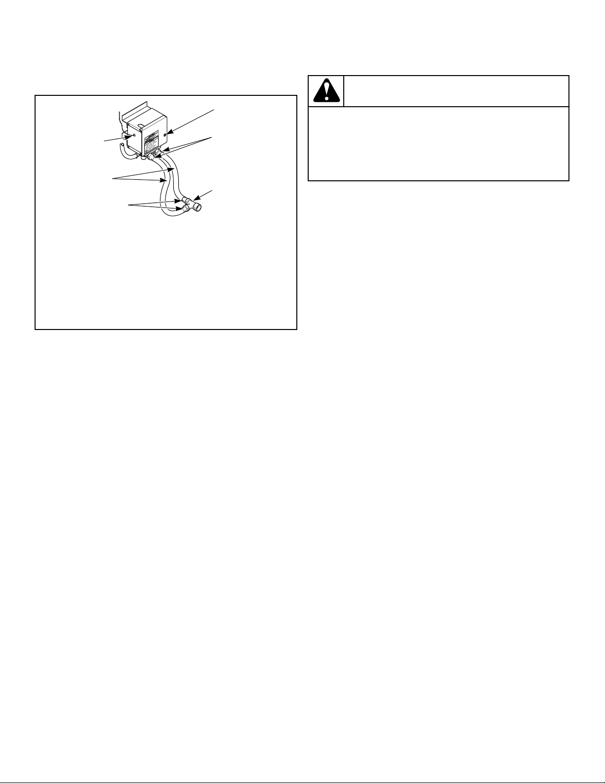
To connect the two hoses (supplied with tumble dryer), insert
rubber washers (from literature pack) in water inlet hose cou-
plings. Refer to Figure 5 .
TMB2008N_SVG
3
2
4
5
2
1
1. Lock
2. Hose Couplings
3. Y Valve
4. Inlet Hoses
5. Opening for Auxiliary Alarm Cable
Figure 5
Connect inlet hoses to water supply. Flush the lines for approxi-
mately two minutes to remove any foreign materials that could
clog the screens in the water mixing valve. This is especially im-
portant when installing a tumble dryer in a newly constructed or
renovated building. Then connect the hoses to the Y-valve; con-
nect the Y-valve to the connections at the rear of the tumble dry-
er.
IMPORTANT: Thread hose couplings onto valve con-
nections finger tight, then turn 1/4 turn with pliers. Do
not cross thread or overtighten couplings.
IMPORTANT: Hoses and other natural rubber parts de-
teriorate after extended use. Hoses may develop
cracks, blisters or material wear from the temperature
and constant high pressure they are subjected to. All
hoses should be checked on a yearly basis for any visi-
ble signs of deterioration. Any hose showing the signs
of deterioration listed above should be replaced imme-
diately. All hoses should be replaced every five years.
NOTE: Longer inlet hoses are available (as optional
equipment at extra cost) if the hoses supplied with the
tumble dryer are not long enough for installation. Order
hoses as follows:
Part No. 20617 Inlet hose 8 feet [2.44 m]
Part No. 20618 Inlet hose 10 feet [3.05 m]
NOTE: Replacement outlet hoses are available (at extra
cost). Order 44073301 Hose, 39 in. [99 cm ].
Electrical Requirements
WARNING
Electrical power must be provided to tumble dryer at
all times. The fire suppression system will be inoper-
ative if the main electrical power supply is discon-
nected.
W690R1
No independent external power source or supply connection is
necessary. Power to operate the 24 Volt fire suppression system is
from the rear junction/contactor box.
Auxiliary Alarm
The fire suppression system provides an auxiliary output signal
when the system is activated. During tumble dryer installation,
you have the option to connect a separate alarm system to this
auxiliary output. Potential uses of the auxiliary output include,
but are not limited to: (1) sounds an alarm, (2) activates a build-
ing sprinkler system, (3) notifies a fire department, etc. Use of the
auxiliary output is not required for the fire suppression system to
operate, but may be used for additional protection.
The connection to the auxiliary output is made through the FS-1
and FS-2 fast-on connections inside the fire suppression control
box. Refer to Figure 6 . The relay is rated for 24 VAC, 5.2 Amp,
sealed current.
NOTE: The auxiliary output is activated during fire sup-
pression system maintenance test sequence. Consider
this fact prior to your system test every three months.
(Example: If the external system uses the auxiliary out-
put to call the fire department, inform the fire depart-
ment before and after the fire suppression system
maintenance test.)
Installation
©
Copyright, Alliance Laundry Systems LLC -
DO NOT COPY or TRANSMIT
25 Part No: 70457901ENR16
TMB1999N_SVG1
6
7
5
4
3
1 2
1. Opening for Auxiliary Alarm Cable
2. Fuse
3. Auxiliary Alarm Fast-On Connection
4. Test Button
5. Light
6. Reset Button
7. Auxiliary Alarm Fast-On Connection
Figure 6
Bolt-On Angle Option
050 Series Tumble Dryers Only
This option allows the tumble dryer depth to be reduced to 34
5/16 inches [871 mm]. The tumble dryer should then fit through a
36 inch [914 mm] door opening (actual 34.5 inches [876 mm ]).
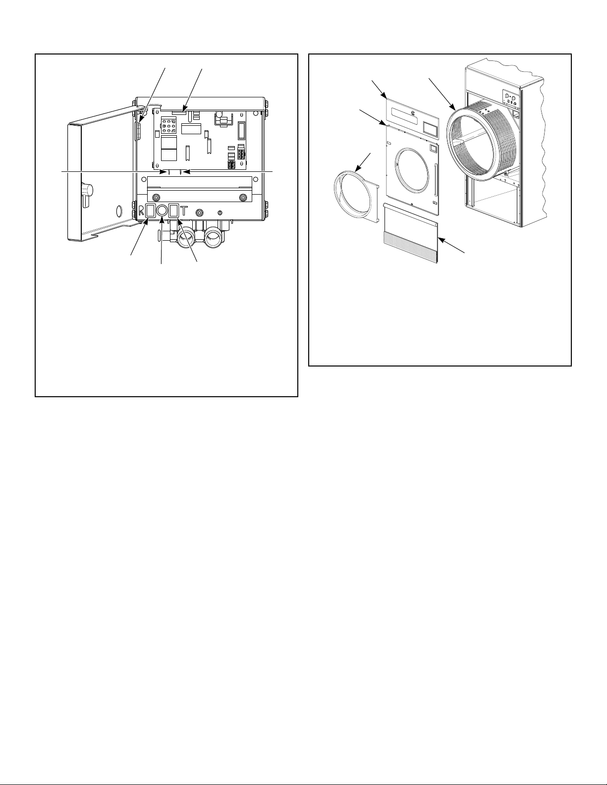
1. Remove the loading door, access panel, front panel and lint
panel. Refer to Figure 7 .
TMB2014K_SVG
1
4
3
2
5
1. Loading Door
2. Front Panel
3. Access Panel
4. Cylinder
5. Lint Panel
Figure 7
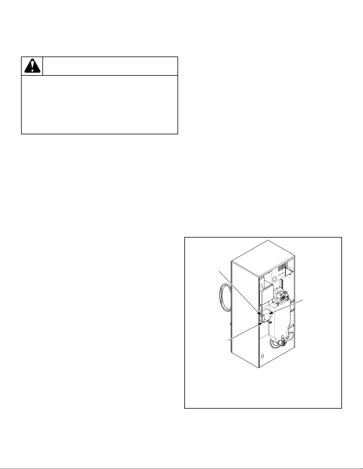
2. Remove the drive guard. Refer to Figure 8 .
Installation
©
Copyright, Alliance Laundry Systems LLC -
DO NOT COPY or TRANSMIT
26 Part No: 70457901ENR16
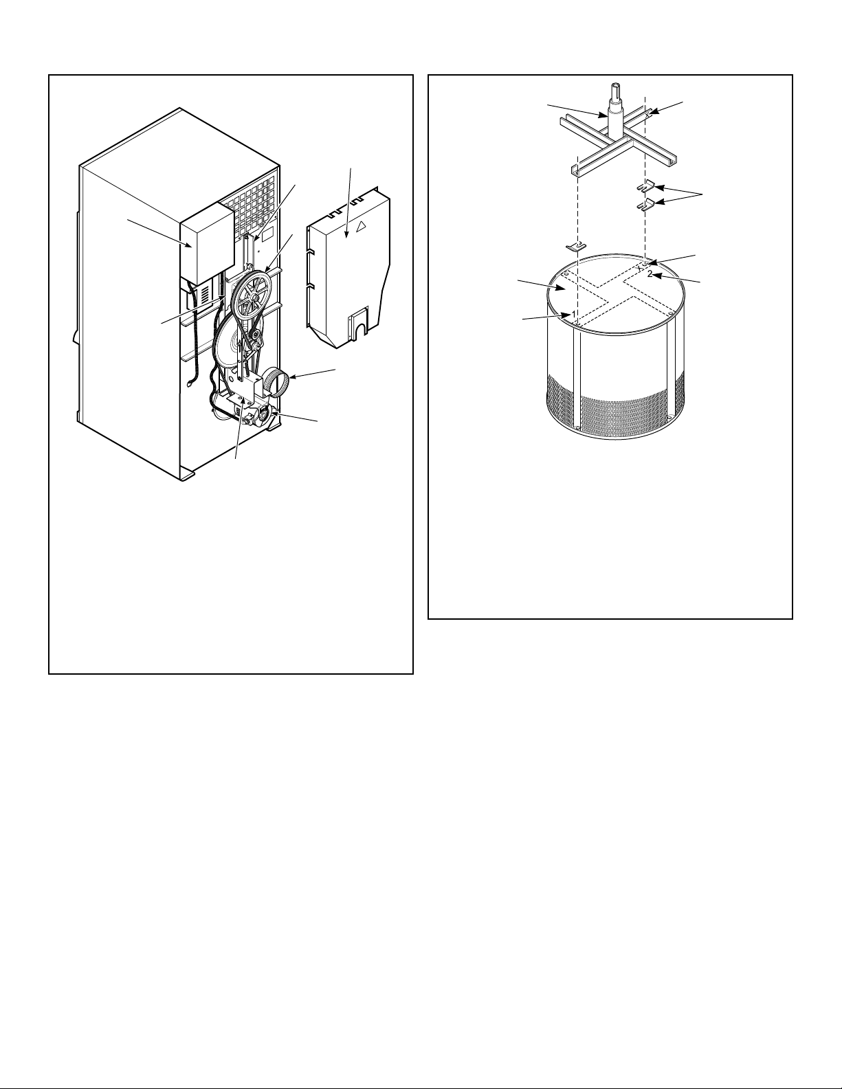
TMB2243N_SVG
2
1
8
7
6
5
4
3
1. Trunnion Housing
2. Junction/Contactor Box
3. Vertical Trunnion Channel
4. Cylinder Pulley
5. Drive Guard
6. Exhaust Thimble
7. Motor
8. Motor Bracket
Figure 8
3. Remove the drive belts. Refer to Figure 8 .
4. Remove the cylinder pulley and shaft key.
5. Pull the cylinder out through the front of the tumble dryer.
Refer to Figure 7 .
6. To ensure proper cylinder balance for reassembly, mark each
channel’s original location on cylinder head and number of
shims for each channel before removal. Refer to Figure 9 .
7. Remove the complete idler assembly.
8. Remove the trunnion housing. Refer to Figure 8 .
9. Disconnect the motor harness(es).
TMB2015K_SVG
4
5
6
2
3
7
1
1. Number of Shims for this Channel
2. Cylinder Head
3. Trunnion
4. Channel Identifier
5. Shims
6. Channel Location
7. Number of Shims for this Channel
Figure 9
10. Remove the motor(s) and motor bracket(s). Refer to Figure
8 .
11. Unbolt and remove the two vertical trunnion channels.
12. Remove the junction/contactor box. Refer to Figure 8 .
13. Remove the exhaust thimble.
14. The gas supply line may require removal if it extends past the
rear panel. If so, disconnect the union located between the gas
and shutoff valves and remove the assembly out through the
front of the tumble dryer.
15. Remove the tumble dryer from the crate base and slide it
through the door, sideways.
16. Refer to the appropriate service video, installation manual and
wiring diagram to reassemble and install the tumble dryer cor-
rectly.
To Reverse the Loading Door
1. Disconnect power supply to tumble dryer.
2. Unlock and remove control panel. Remove two control as-
sembly mounting screws from right side. Swing open control
Installation
©
Copyright, Alliance Laundry Systems LLC -
DO NOT COPY or TRANSMIT
27 Part No: 70457901ENR16
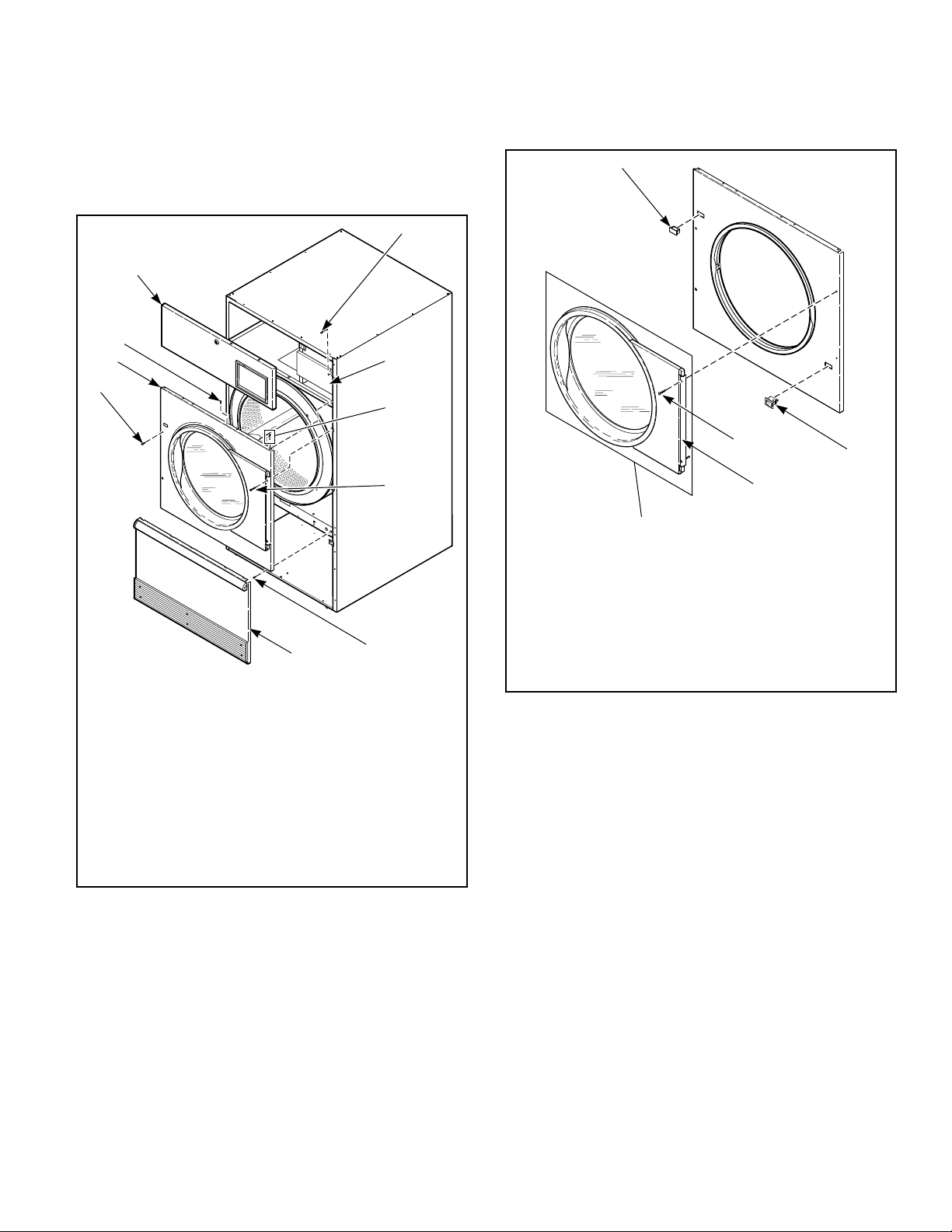
to access upper flange right guide lug assembly. Refer to Fig-
ure 10 .
3. Remove lint panel.
IMPORTANT: Support door and hinge assembly se-
curely to prevent it from dropping once side screws
are removed from door hinge lug.
TMB2495P_SVG
2
3
1
4
4
8
7
5
5
6
1. Control Assembly Mounting Screw
2. Control Assembly
3. Guide Lug Assembly
4. Side Screw
5. Screw
6. Lint Panel
7. Front Panel
8. Control Panel
Figure 10
4. Remove four front panel screws. Refer to Figure 10 . Keep
door hinge cams in place on door hinge lug. Pull lug and door
assembly off as one piece. Refer to Figure 11 .
5. Remove remaining front panel screws. Refer to Figure 10 .
Disconnect door switch harness from switch. Take off front
panel. Refer to Figure 11 .
6. Exchange switch and plug locations. Depress tabs with an ad-
justable pliers to remove plug and switch from front panel.
Reinstall switch, orienting button toward center of machine.
Reinstall plug in switch’s previous location. Refer to Figure
11 .
IMPORTANT: Door switch must be oriented correctly in
front panel receiving hole or tumble dryer will not oper-
ate.
TMB1995N_SVG
2
3
4
5
1
1. Plug
2. Switch
3. Side Screw
4. Door Hinge Lug
5. Door Assembly
Figure 11
7. Cut wire ties to remove door switch harness bundle. Be care-
ful not to damage harness wires. Refer to Figure 12 .
8. Reroute door switch harness up through the hole in the right
side of the top panel. Use the panel cutout opening to then put
harness down through the hole in the left side of the top panel
and into the upper left corner of the cylinder enclosure.
Installation
©
Copyright, Alliance Laundry Systems LLC -
DO NOT COPY or TRANSMIT
28 Part No: 70457901ENR16
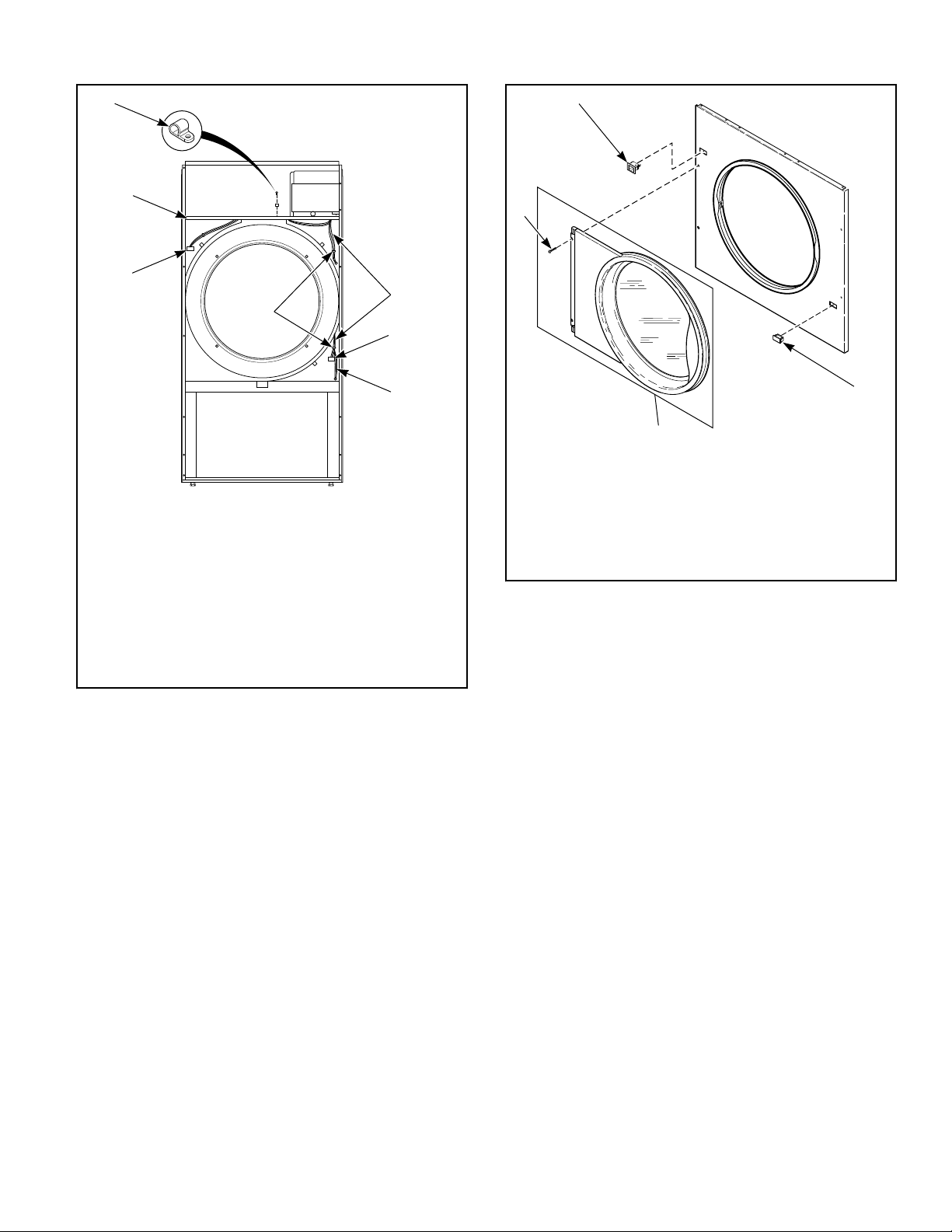
TMB2496N_SVG
6
7
1
5
4
3
2
1. Screw Cable Clamp
2. Beginning Location of Door Switch Harness
3. Original Switch Location
4. Lint Panel Switch Harness
5. Wire Ties
6. Original Plug Location
7. Top Panel
Figure 12
9. Place front panel on machine, loosely attach four bottom
screws. Connect door switch harness to switch in new loca-
tion. Install door assembly and four front panel side screws
loosely. Refer to Figure 13 .
10. Check lint panel fit, adjusting front panel up or down as re-
quired. Tighten four front panel side screws to maintain posi-
tion of front panel for proper lint panel clearance.
11. Remove lint panel. Fully tighten bottom screws on front pan-
el.
12. Reinstall top screws and guide lugs.
13. Adjust door catch if necessary to allow 8 – 15 pounds [35.6N
– 66.7N] pull at center of handle.
14. Reinstall control assembly using mounting screws.
15. Reinstall control panel and lint panel.
IMPORTANT: Restore power to tumble dryer and
test for proper operation of loading door switch. Re-
fer to Loading Door Switch section for adjustment pro-
cedure. Tumble dryer should not start with door
open; an operating tumble dryer should stop when
door is opened.
TMB1997N_SVG
2
3
1
4
1. Switch (New location)
2. Plug (New location)
3. Door Assembly
4. Side Screw
Figure 13
NOTE: If machine is converted back to right hand hinge
operation, the door switch harness must be rerouted.
Before Placing Tumble Dryer into
Service
1. Remove or open all panels and check accessible bolts, nuts,
screws, terminals and fittings for tightness.
2. Check belt tension and adjust if necessary. Refer to Adjust-
ments section.
3. Replace all panels and guards.
4. Turn on electrical supply to tumble dryer.
5. Open the supply valve for gas or steam heated tumble dryers.
6. After performing the previous checks, start the tumble dryer
by pressing START. (Refer to the Operating section for de-
tailed instructions.) Release the start button and open the
loading door. The cylinder should stop rotating within seven
seconds after the door is opened a maximum of 2 inches [51
mm]. If it does not, adjust the loading door switch. Refer to
Adjustments section.
7. Gas Tumble Dryers: Start the tumble dryer and check the
burner flame. Adjust the air inlet shutter as required. Refer to
Adjustments section.
Installation
©
Copyright, Alliance Laundry Systems LLC -
DO NOT COPY or TRANSMIT
29 Part No: 70457901ENR16
IMPORTANT: The electronic ignition system will at-
tempt to light the gas by sparking for the “trial for
ignition” period. If gas does not ignite within this
period, the ignition control will go into a safety lock-
out and the valve will no longer open until the con-
trol is reset. It may be necessary to retry several
times to bleed air from the gas lines. To reset, open
and close the loading door and restart tumble dryer.
If lockout condition persists, check that the manual
gas shut-off valve is in the ON position and that the
gas service is properly connected. If condition still
persists, remove tumble dryer from service.
8. Load the cylinder with a full load of clean rags and run to re-
move oil or dirt from cylinder.
9. Check the airflow switch operation by opening the lint panel;
be sure to remove shipping tape from airflow switch prior to
operation. Temporarily tape down the lint panel safety switch
located behind the upper left corner of the lint panel. The
heating systems should shut off when the lint panel is opened
a maximum of 1.5 inches [ 38 mm].
The airflow switch operation may be affected by shipping tape
still in place, lack of make-up air, or an obstruction in the exhaust
duct. These should be checked. If there is a problem, contact an
authorized service person.
WARNING
Do not operate tumble dryer if airflow switch is
faulty. An explosive gas mixture could collect in
tumble dryer if airflow switch does not operate
properly.
W407R1
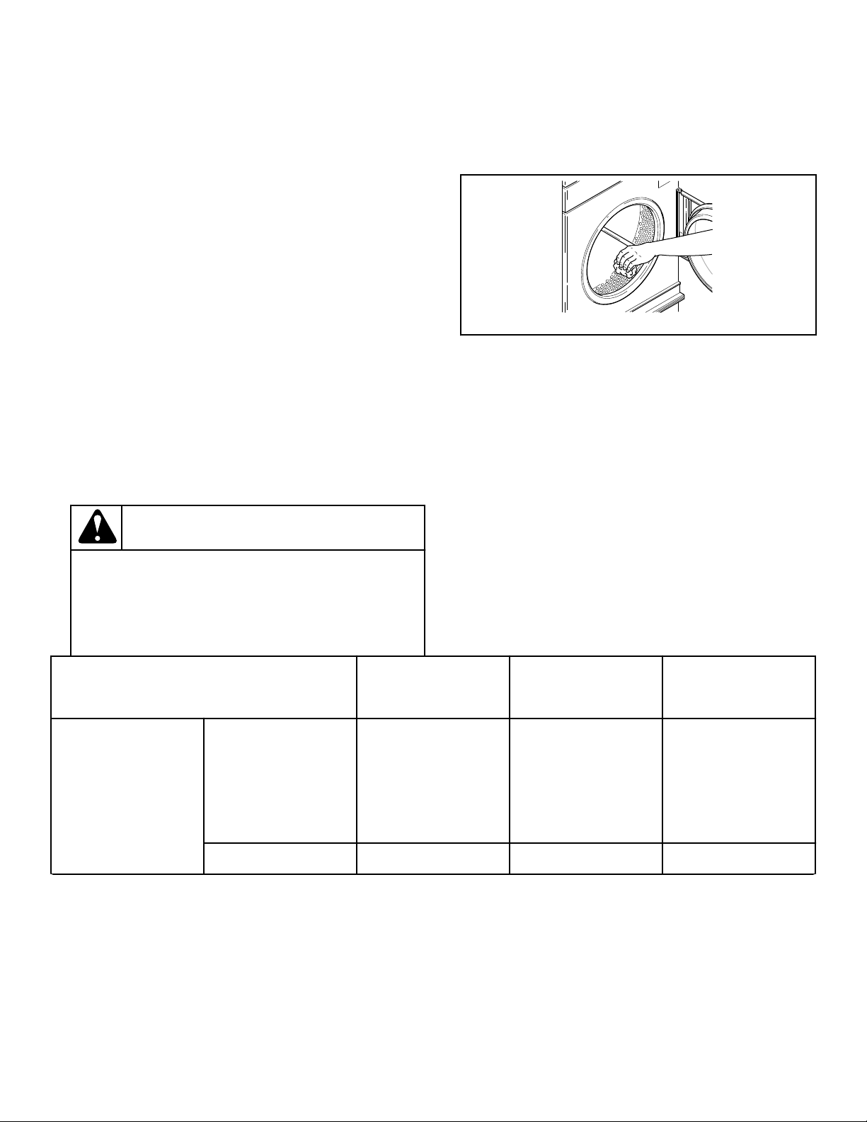
10. Wipe out the cylinder using an all-purpose cleaner or deter-
gent and water solution. Refer to Figure 14 .
IMPORTANT: The use of chlorine bleach for remov-
ing any discoloration should be avoided because
bleach could damage the finish.
T452I_SVG
Figure 14
Models
Prepurge Time
(seconds)
Trial for Ignition
(seconds)
Reset Lockout
Condition By:
Models through
3/10/13
CE and
Australia
18 10 025, 030, 035, 055:
Press reset button on
rear of machine
T30, T45: Press lighted
reset button in rear
contactor box
All others 1-3 10 Open loading door
Table continues...
Installation
©
Copyright, Alliance Laundry Systems LLC -
DO NOT COPY or TRANSMIT
30 Part No: 70457901ENR16
Loading...