


 Loading...
Tumble Dryers
120 Pound (55 Kilogram) Capacity
170 Pound (77 Kilogram) Capacity
200 Pound (90 Kilogram) Capacity Starting Serial No. 0907003062 Refer to Page 8 for Model Identification
Installation/Operation/Maintenance
Original Instructions
Keep These Instructions for Future Reference.
(If this machine changes ownership, this manual must accompany machine.)
TMB1268C_SVG
www.alliancelaundry.com |
Part No. 70458101ENR13 |
|
June 2017 |

Installation must conform with local codes or, in the absence of local codes, with:
In the U.S.A., installation must conform to the latest edition of the American National Standard Z223.1/ NFPA 54 “National Fuel Gas Code” and Standard ANSI/NFPA 70 “National Electric Code.”
In Canada, installation must comply with Standards CAN/CSA-B149.1 or Natural Gas and Propane Installation Code and CSA C22.1, latest edition, Canadian Electric Code, Part I.
In Australia and New Zealand, installation must comply with the Gas Installations Standard AS/NZS 5601 Part 1: General Installations.
WARNING
FOR YOUR SAFETY, the information in this manual must be followed to minimize the risk of fire or explosion or to prevent property damage, personal injury or death.
W033
WARNING
•Do not store or use gasoline or other flammable vapors and liquids in the vicinity of this or any other appliance.
•WHAT TO DO IF YOU SMELL GAS:
•Do not try to light any appliance.
•Do not touch any electrical switch; do not use any phone in your building.
•Clear the room, building or area of all occupants.
•Immediately call your gas supplier from a neighbor’s phone. Follow the gas supplier’s instructions.
•If you cannot reach your gas supplier, call the fire department.
•Installation and service must be performed by a qualified installer, service agency or the gas supplier.
W052
IMPORTANT: Information must be obtained from a local gas supplier on instructions to be followed if the user smells gas. These instructions must be posted in a prominent location. Step-by-step instructions of the above safety information must be posted in a prominent location near the tumble dryer for customer use.
IMPORTANT: The installer must fully test the tumble dryer after installation and demonstrate to the owner how to operate the machine.
WARNING
To reduce the risk of electric shock, fire, explosion, serious injury or death:
•Disconnect electric power to the tumble dryer before servicing.
•Close gas shut-off valve to gas tumble dryer before servicing.
•Close steam valve to steam tumble dryer before servicing.
•Never start the tumble dryer with any guards/panels removed.
•Whenever ground wires are removed during servicing, these ground wires must be reconnected to ensure that the tumble dryer is properly grounded.
W002R1
© Copyright, Alliance Laundry Systems LLC - |
3 |
Part No. 70458101ENR13 |
DO NOT COPY or TRANSMIT |
|
|

WARNING
•Installation of unit must be performed by a qualified installer.
•Install tumble dryer according to manufacturer’s instructions and local codes.
•DO NOT install a tumble dryer with flexible plastic venting materials. If flexible metal (foil type) duct is installed, it must be of a specific type identified by the appliance manufacturer as suitable for use with tumble dryer. Refer to section on connecting exhaust system. Flexible venting materials are known to collapse, be easily crushed, and trap lint. These conditions will obstruct tumble dryer airflow and increase the risk of fire.
W752R1
The following information applies to the state of Massachusetts, USA.
•This appliance can only be installed by a Massachusetts licensed plumber or gas fitter.
•This appliance must be installed with a 36 inch [91 cm] long flexible gas connector.
•A “T-Handle” type gas shut-off valve must be installed in the gas supply line to this appliance.
•This appliance must not be installed in a bedroom or bathroom.
© Copyright, Alliance Laundry Systems LLC - |
4 |
Part No. 70458101ENR13 |
DO NOT COPY or TRANSMIT |
|
|
Table of Contents |
|
Introduction........................................................................................... |
8 |
Model Identification ....................................................................................... |
8 |
Contact Information...................................................................................... |
10 |
Manufacturing Date ...................................................................................... |
11 |
................................................................................................................ |
11 |
Safety Information................................................................................ |
12 |
Explanation of Safety Messages..................................................................... |
12 |
Important Safety Instructions......................................................................... |
12 |
Specifications and Dimensions.............................................................. |
14 |
Specifications and Dimensions ...................................................................... |
14 |
120 Series Tumble Dryer Dimensions and Exhaust Outlet Locations ................. |
16 |
170 and 200 Series Tumble Dryer Dimensions and Exhaust Outlet Locations..... |
17 |
Electric and Gas Connection Locations for Gas Models Through 3/10/13........... |
18 |
Electric and Gas Connection Locations for Gas Models Starting 3/11/13............ |
19 |
Electric and Steam Connection Locations for Steam Models Through 3/10/13.... |
20 |
Electric and Steam Connection Locations for Steam Models Starting 3/11/13..... |
21 |
Electric Connection Location for Electric Models............................................ |
23 |
Installation........................................................................................... |
24 |
Pre-Installation Inspection............................................................................. |
24 |
Location Requirements.................................................................................. |
24 |
Position and Level the Tumble Dryer.............................................................. |
25 |
Mounting..................................................................................................... |
25 |
Fire Suppression System (Optional Equipment)............................................... |
26 |
Check Local Codes and Permits.................................................................. |
26 |
Water Requirements................................................................................... |
26 |
Water Connections..................................................................................... |
26 |
Electrical Requirements............................................................................. |
28 |
Auxiliary Alarm........................................................................................ |
28 |
Before Placing Tumble Dryer into Service....................................................... |
28 |
Required for CE Models Only.................................................................... |
30 |
Installing CE Gas Drying Tumble Dryer.......................................................... |
30 |
General Information.................................................................................. |
30 |
CE Orifices............................................................................................... |
31 |
Properties of CE Gases.............................................................................. |
33 |
Changing Gas Configuration...................................................................... |
33 |
Specific Conversion Procedures.................................................................. |
34 |
© Copyright 2017, Alliance Laundry Systems LLC
All rights reserved. No part of the contents of this book may be reproduced or transmitted in any form or by any means without the expressed written consent of the publisher.
© Copyright, Alliance Laundry Systems LLC - |
5 |
Part No. 70458101ENR13 |
DO NOT COPY or TRANSMIT |
|
|
Exhaust Requirements.......................................................................... |
36 |
Exhaust Requirements................................................................................... |
36 |
Layout......................................................................................................... |
36 |
Make-Up Air................................................................................................ |
36 |
Venting........................................................................................................ |
36 |
Alternate Venting for 120 Series Tumble Dryers........................................... |
38 |
Individual Venting..................................................................................... |
38 |
Manifold Venting...................................................................................... |
39 |
Gas Requirements................................................................................. |
42 |
Gas Requirements......................................................................................... |
42 |
Gas Supply Pipe Sizing and Looping.............................................................. |
44 |
Low Pressure Gas Pipe Sizes...................................................................... |
45 |
High Pressure Gas Pipe Sizes..................................................................... |
47 |
High Altitude Orifice Sizing ......................................................................... |
49 |
Electrical Requirements........................................................................ |
52 |
Electrical Requirements................................................................................. |
52 |
Wiring Diagram............................................................................................ |
52 |
Grounding Instructions.................................................................................. |
52 |
For CE Models Only.................................................................................. |
53 |
Service/Ground Location........................................................................... |
53 |
To Connect Electrical Service To The Tumble Dryer........................................ |
55 |
Jumper Configuration Instructions.................................................................. |
55 |
Ferrite Ring Installation ................................................................................ |
55 |
Electrical Specifications ............................................................................... |
58 |
Steam Requirements............................................................................. |
60 |
Steam Requirements...................................................................................... |
60 |
Piping Recommendations.............................................................................. |
64 |
Installing Steam Trap and Making Condensate Return Connections................... |
64 |
Thermal Oil Prep.......................................................................................... |
64 |
Operating Instructions.......................................................................... |
65 |
Operating Instructions................................................................................... |
65 |
Emergency Stop Button On CE Models.......................................................... |
65 |
Operating Instructions................................................................................... |
65 |
Reversing Operation...................................................................................... |
66 |
Control Instructions....................................................................................... |
66 |
Dual Digital Timer Control......................................................................... |
66 |
Electronic OPL Micro Control.................................................................... |
68 |
LED OPL Control .................................................................................... |
69 |
UniLinc Control ....................................................................................... |
70 |
DX4 OPL Control..................................................................................... |
71 |
Diagnostic Microprocessor Control ............................................................ |
72 |
DMP OPL Models..................................................................................... |
72 |
Ignition Control Operation and Troubleshooting for Models Starting 3/11/13..... |
74 |
© Copyright, Alliance Laundry Systems LLC - |
6 |
Part No. 70458101ENR13 |
DO NOT COPY or TRANSMIT |
|
|
Internal Control Failure.............................................................................. |
75 |
Troubleshooting........................................................................................ |
75 |
Proper Electrode Location.......................................................................... |
76 |
Flame Current Measurement....................................................................... |
76 |
Ignition Control Operation for Non-CE Models Through 3/10/13...................... |
76 |
Ignition Control Operation for CE Models Through 3/10/13............................. |
76 |
System Tests............................................................................................. |
77 |
Diagnostic LED (DGN LED)/Error Codes................................................... |
77 |
Adjustments......................................................................................... |
79 |
Adjustments................................................................................................. |
79 |
Gas Burner Air Shutter.................................................................................. |
79 |
Airflow Switch ............................................................................................ |
80 |
Loading Door Switch.................................................................................... |
80 |
Loading Door Catch (120 and 170 Series Models)........................................... |
80 |
Loading Door Strike (200 Series Models)........................................................ |
81 |
Belt Drive ................................................................................................... |
81 |
Maintenance......................................................................................... |
83 |
Daily........................................................................................................... |
83 |
Monthly....................................................................................................... |
83 |
Quarterly...................................................................................................... |
83 |
Bi-Annually................................................................................................. |
84 |
Annually...................................................................................................... |
84 |
Fire Suppression System (Optional Equipment) Maintenance Test..................... |
84 |
Before You Call for Service................................................................... |
86 |
Removing Tumble Dryer from Service.................................................. |
87 |
Disposal of Unit.................................................................................... |
88 |
China Restriction of hazardous substances (RoHS)............................... |
89 |
© Copyright, Alliance Laundry Systems LLC - |
7 |
Part No. 70458101ENR13 |
DO NOT COPY or TRANSMIT |
|
|

Introduction
Introduction
Model Identification
Information in this manual is applicable to these models. Refer to the machine serial plate for the model number.
|
|
Gas |
|
|
Steam/Thermal Oil |
|
Electric |
|
|
|
|
|
|
|
|
|
|
|
|
|
120 Series |
BA120L |
IT120L |
SA120N |
BH120S |
|
PH120S |
BH120E |
|
|
(55 Kg) |
BA120N |
IT120N |
SH120L |
BT120S |
|
PT120S |
BT120E |
|
|
|
BH120L |
LA120L |
SH120N |
BT120T |
|
PT120T |
BU120E |
|
|
|
BH120N |
LA120N |
SK120N |
BU120S |
|
PU120S |
CT120E |
|
|
|
BK120N |
LK120N |
ST120L |
BU120T |
|
PU120T |
CU120E |
|
|
|
BT120L |
LT120L |
ST120N |
CT120S |
|
SH120S |
HH120E |
|
|
|
BT120N |
LT120N |
SU120L |
CT120T |
|
ST120S |
HT120E |
|
|
|
BU120L |
LU120L |
SU120N |
CU120S |
|
ST120T |
HU120E |
|
|
|
BU120N |
LU120N |
UA120L |
CU120T |
|
SU120S |
IT120E |
|
|
|
CA120L |
NH120L |
UA120N |
HH120S |
|
SU120T |
LT120E |
|
|
|
CA120N |
NH120N |
UH120L |
HT120S |
|
UH120S |
LU120E |
|
|
|
CK120N |
NT120L |
UH120N |
HT120T |
|
UT120S |
NH120E |
|
|
|
CT120L |
NT120N |
UK120N |
HU120S |
|
UT120T |
NT120E |
|
|
|
CT120N |
NU120L |
UT120L |
HU120T |
|
UU120S |
NU120E |
|
|
|
CU120L |
NU120N |
UT120N |
IT120S |
|
UU120T |
PH120E |
|
|
|
CU120N |
PA120L |
UU120L |
IT120T |
|
XT120S |
PT120E |
|
|
|
HA120L |
PA120N |
UU120N |
LT120S |
|
XT120T |
PU120E |
|
|
|
HA120N |
PH120L |
XT120L |
LT120T |
|
XU120S |
SH120E |
|
|
|
HH120L |
PH120N |
XT120N |
LU120S |
|
XU120T |
ST120E |
|
|
|
HH120N |
PK120N |
XU120L |
LU120T |
|
YT120S |
SU120E |
|
|
|
HK120N |
PT120L |
XU120N |
NH120S |
|
YT120T |
UH120E |
|
|
|
HT120L |
PT120N |
YT120L |
NT120S |
|
YU120S |
UT120E |
|
|
|
HT120N |
PU120L |
YT120N |
NU120S |
|
YU120T |
UU120E |
|
|
|
HU120L |
PU120N |
YU120L |
|
|
|
YT120E |
|
|
|
HU120N |
SA120L |
YU120N |
|
|
|
YU120E |
|
|
|
|
|
|
|
|
|
|
|
Table continues...
© Copyright, Alliance Laundry Systems LLC - |
8 |
Part No. 70458101ENR13 |
DO NOT COPY or TRANSMIT |
|
|

|
|
|
|
|
|
|
|
Introduction |
|
|
|
|
|
|
|
|
|
|
|
|
|
Gas |
|
|
Steam/Thermal Oil |
|
Electric |
|
|
|
|
|
|
|
|
|
|
|
|
|
170 Series |
BA170L |
IT170L |
SA170N |
BH170S |
|
PH170S |
Not Applicable |
|
|
(77 Kg) |
BA170N |
IT170N |
SH170L |
BT170S |
|
PT170S |
|
|
|
|
BH170L |
LA170L |
SH170N |
BT170T |
|
PT170T |
|
|
|
|
BH170N |
LA170N |
SK170N |
BU170S |
|
PU170S |
|
|
|
|
BK170N |
LK170N |
ST170L |
BU170T |
|
PU170T |
|
|
|
|
BT170L |
LT170L |
ST170N |
CT170S |
|
SH170S |
|
|
|
|
BT170N |
LT170N |
SU170L |
CT170T |
|
ST170S |
|
|
|
|
BU170L |
LU170L |
SU170N |
CU170S |
|
ST170T |
|
|
|
|
BU170N |
LU170N |
UA170L |
CU170T |
|
SU170S |
|
|
|
|
CA170L |
NH170L |
UA170N |
HH170S |
|
SU170T |
|
|
|
|
CA170N |
NH170N |
UH170L |
HT170S |
|
UH170S |
|
|
|
|
CK170N |
NT170L |
UH170N |
HT170T |
|
UT170S |
|
|
|
|
CT170L |
NT170N |
UK170N |
HU170S |
|
UT170T |
|
|
|
|
CT170N |
NU170L |
UT170L |
HU170T |
|
UU170S |
|
|
|
|
CU170L |
NU170N |
UT170N |
IT170S |
|
UU170T |
|
|
|
|
CU170N |
PA170L |
UU170L |
IT170T |
|
XT170S |
|
|
|
|
HA170L |
PA170N |
UU170N |
LT170S |
|
XT170T |
|
|
|
|
HA170N |
PH170L |
XT170L |
LT170T |
|
XU170S |
|
|
|
|
HH170L |
PH170N |
XT170N |
LU170S |
|
XU170T |
|
|
|
|
HH170N |
PK170N |
XU170L |
LU170T |
|
YT170S |
|
|
|
|
HK170N |
PT170L |
XU170N |
NH170S |
|
YT170T |
|
|
|
|
HT170L |
PT170N |
YT170L |
NT170S |
|
YU170S |
|
|
|
|
HT170N |
PU170L |
YT170N |
NU170S |
|
YU170T |
|
|
|
|
HU170L |
PU170N |
YU170L |
|
|
|
|
|
|
|
HU170N |
SA170L |
YU170N |
|
|
|
|
|
|
|
|
|
|
|
|
|
|
|
Table continues...
© Copyright, Alliance Laundry Systems LLC - |
9 |
Part No. 70458101ENR13 |
DO NOT COPY or TRANSMIT |
|
|
Introduction
|
|
Gas |
|
|
|
|
Steam/Thermal Oil |
Electric |
||
|
|
|
|
|
|
|
|
|
|
|
200 Series |
|
BA200L |
|
HU200L |
PT200L |
|
BH200S |
|
LU200T |
Not Applicable |
(90 Kg) |
|
BA200N |
|
HU200N |
PT200N |
|
BT200S |
|
NH200L |
|
|
|
BH200L |
|
IT200L |
PU200L |
|
BT200T |
|
NT200S |
|
|
|
BH200N |
|
IT200N |
PU200N |
|
BU200S |
|
NU200S |
|
|
|
BT200L |
|
LA200L |
SA200L |
|
BU200T |
|
PH200L |
|
|
|
BT200N |
|
LA200N |
SA200N |
|
CT200S |
|
PT200S |
|
|
|
BU200L |
|
LT200L |
SH200L |
|
CT200T |
|
PT200T |
|
|
|
BU200N |
|
LT200N |
SH200N |
|
CU200S |
|
PU200S |
|
|
|
CA200L |
|
LU200L |
ST200L |
|
CU200T |
|
PU200T |
|
|
|
CA200N |
|
LU200N |
ST200N |
|
HH200S |
|
SH200L |
|
|
|
CT200L |
|
NH200L |
SU200L |
|
HT200S |
|
ST200S |
|
|
|
CT200N |
|
NH200N |
SU200N |
|
HT200T |
|
ST200T |
|
|
|
CU200L |
|
NT200L |
UA200L |
|
HU200S |
|
SU200S |
|
|
|
CU200N |
|
NT200N |
UA200N |
|
HU200T |
|
SU200T |
|
|
|
HA200L |
|
NU200L |
UH200L |
|
IT200S |
|
UH200L |
|
|
|
HA200N |
|
NU200N |
UH200N |
|
IT200T |
|
UT200S |
|
|
|
HH200L |
|
PA200L |
UT200L |
|
LT200S |
|
UT200T |
|
|
|
HH200N |
|
PA200N |
UT200N |
|
LT200T |
|
UU200S |
|
|
|
HT200L |
|
PH200L |
UU200L |
|
LU200S |
|
UU200T |
|
|
|
HT200N |
|
PH200N |
UU200N |
|
|
|
|
|
|
|
|
|
|
|
|
|
|
|
|
Explanation of digit in 6th position of model number: |
|
|
|
|
|
|
||||
E = Electric |
|
|
|
|
|
|
|
|
|
|
|
|
|
|
|
|
|
|
|
||
L = Liquid Petroleum (L.P.) Gas |
|
|
|
|
|
|
|
|
||
|
|
|
|
|
|
|
|
|
|
|
N = Natural Gas |
|
|
|
|
|
|
|
|
|
|
|
|
|
|
|
|
|
|
|
|
|
S = Steam |
|
|
|
|
|
|
|
|
|
|
|
|
|
|
|
|
|
|
|
|
|
T = Thermal Oil |
|
|
|
|
|
|
|
|
|
|
|
|
|
|
|
|
|
|
|||
Includes models with the following control suffixes |
|
|
|
|
|
|
||||
R3 – reversing DX4 OPL |
|
RE – reversing LED OPL |
|
RQ – reversing dual digital timer |
||||||
|
|
|
|
|||||||
RD – reversing DMP OPL |
|
RM – reversing OPL micro |
RU – reversing UniLinc OPL |
|||||||
|
|
|
|
|
|
|
|
|
|
|
Contact Information
If service is required, contact the nearest Factory Authorized Service Center.
If you are unable to locate an authorized service center or are unsatisfied with the service performed on your unit, contact:
Alliance Laundry Systems Shepard Street
P.O. Box 990
Ripon, WI 54971-0990 U.S.A. www.alliancelaundry.com
© Copyright, Alliance Laundry Systems LLC - |
10 |
Part No. 70458101ENR13 |
DO NOT COPY or TRANSMIT |
|
|
Introduction
Phone: +1 (920) 748-3121
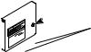
When calling or writing about your unit, PLEASE GIVE THE MODEL AND SERIAL NUMBERS. The model and serial numbers are located on the serial plate. The serial plate will be in the location shown in Figure 1 .
Date Purchased
Model Number
Serial Number
Please include a copy of your bill of sale and any service receipts you have.
WARNING
To reduce the risk of serious injury or death, DO NOT repair or replace any part of the unit or attempt any servicing unless specifically recommended in the user-maintenance instructions or in published userrepair instructions that you understand and have the skills to carry out.
W329
If replacement parts are required, contact the source from where you purchased your unit or call +1 (920) 748-3950 for the name and address of the nearest authorized parts distributor.
1 |
120 |
1. Serial Plate
1 |
170/200 |
TMB2288N_SVG |
Figure 1
Manufacturing Date
The manufacturing date for your unit can be found on the serial number. The first two digits indicate the year. The third and fourth digits indicate the month. For example, a unit with serial number 1505000001 was manufactured in May 2015.
© Copyright, Alliance Laundry Systems LLC - |
11 |
Part No. 70458101ENR13 |
DO NOT COPY or TRANSMIT |
|
|
Safety Information
Safety Information
Explanation of Safety Messages
Precautionary statements (“DANGER,” “WARNING,” and “CAUTION”), followed by specific instructions, are found in this manual and on machine decals. These precautions are intended for the personal safety of the operator, user, servicer, and those maintaining the machine.
DANGER
Indicates an imminently hazardous situation that, if not avoided, will cause severe personal injury or death.
WARNING
Indicates a hazardous situation that, if not avoided, could cause severe personal injury or death.
CAUTION
Indicates a hazardous situation that, if not avoided, may cause minor or moderate personal injury or property damage.
Additional precautionary statements (“IMPORTANT” and “NOTE”) are followed by specific instructions.
IMPORTANT: The word “IMPORTANT” is used to inform the reader of specific procedures where minor machine damage will occur if the procedure is not followed.
NOTE: The word “NOTE” is used to communicate installation, operation, maintenance or servicing information that is important but not hazard related.
Important Safety Instructions
WARNING
To reduce the risk of fire, electric shock, serious injury or death to persons when using your tumble dryer, follow these basic precautions.
W776R1
Save These Instructions
•Read all instructions before using the tumble dryer.
•Install the tumble dryer according to the INSTALLATION instructions. Refer to the EARTHING (grounding) instructions for the proper earthing (grounding) of the tumble dryer. All connections for electrical power, earthing (grounding) and gas supply must comply with local codes and be made by licensed personnel when required. It is recommended that the machine be installed by qualified technicians.
•Do not install or store the tumble dryer where it will be exposed to water and/or weather. The tumble dryer cannot be used in a closed room where the air supply is insufficient. If necessary, ventilation grids must be installed in the doors or the windows.
•This tumble dryer must not be activated without lint screen filter.
•When you perceive a gas odor, immediately shut off the gas supply and ventilate the room. Do not power on electrical appliances and do not pull electrical switches. Do not use matches or lighters. Do not use a phone in the building. Warn the installer, and if so desired, the gas company, as soon as possible.
•To avoid fire and explosion, keep surrounding areas free of flammable and combustible products. Regularly clean the cylinder and exhaust tube should be cleaned periodically by competent maintenance personnel. Daily remove debris from lint screen filter and inside of filter compartment.
•Do not use or store flammable materials near this appliance.
•Do not place into tumble dryer articles that have been previously cleaned in, washed in, soaked in or spotted with gasoline or machine oils, vegetable or cooking oils, cleaning waxes or chemicals, dry-cleaning solvents, thinner or other flammable or explosive substances as they give off vapors that could ignite, explode or cause fabric to catch on fire by itself.
•Do not spray aerosols in the vicinity of this appliance while it is in operation.
•Items such as foam rubber (latex foam), shower caps, waterproof textiles, rubber backed articles and clothes or pillows filled with foam rubber pads should not be dried in the tumble dryer. Do not use the appliance to dry materials with a low melting temperature (PVC, rubber, etc.).
•Do not tumble fiberglass curtains and draperies unless the label says it can be done. If they are dried, wipe out the cylinder with a damp cloth to remove particles of fiberglass.
•Do not allow children to play on or in the washer. Close supervision of children is necessary when the washer is used near children. This appliance is not intended for use by persons (including children) with reduced physical, sensory or mental capabilities, or lack of experience and knowledge, unless they have been given supervision or instruction concerning the use of the appliance by a person responsible for their safety. This is a safety rule for all appliances.
•Cleaning and user maintenance shall not be made by children without supervision.
© Copyright, Alliance Laundry Systems LLC - |
12 |
Part No. 70458101ENR13 |
DO NOT COPY or TRANSMIT |
|
|
•Children less than three years should be kept away unless continuously supervised.
•Do not reach into the tumble dryer if the cylinder is revolving.
•Use tumble dryer only for its intended purpose, drying fabrics. Always follow the fabric care instructions supplied by the textile manufacturer and only use the dryer to dry textiles that have been washed in water. Only insert spin-dried linen in the dryer to avoid damage to dryer.
•Always read and follow manufacturer’s instructions on packages of laundry and cleaning aids. Follow all warnings or precautions. To reduce the risk of poisoning or chemical burns, keep them out of the reach of children at all times (preferably in a locked cabinet).
•Do not use fabric softeners or products to eliminate static unless recommended by the manufacturer of the fabric softener or product.
•Remove laundry immediately after tumble dryer stops.
•DO NOT operate the tumble dryer if it is smoking, grinding or has missing or broken parts or removed guards or panels. DO NOT tamper with the controls or bypass any safety devices.
•Tumble dryer will not operate with the loading door open. DO NOT bypass the door safety switch to permit the tumble dryer to operate with the door open. The tumble dryer will stop rotating when the door is opened. Do not use the tumble dryer if it does not stop rotating when the door is opened or starts tumbling without pressing the START mechanism. Remove the tumble dryer from use and call for service.
•Tumble dryer will not operate with lint panel open. DO NOT bypass lint panel door safety switch to permit the tumble dryer to operate with the lint panel door open.
•Do not alter this tumble dryer from factory construction except as otherwise described in the technical instructions.
•Always clean the lint filter daily. Keep area around the exhaust opening and adjacent surrounding area free from the accumulation of lint, dust and dirt. The interior of the tumble dryer and the exhaust duct should be cleaned periodically by qualified service personnel.
•Solvent vapors from dry-cleaning machines create acids when drawn through the heater of the drying unit. These acids are corrosive to the tumble dryer as well as the laundry load being dried. Be sure make-up air is free of solvent vapors.
•At the end of each working day, close off all main supplies of gas, steam and electricity.
IMPORTANT: For fire suppression equipped tumble dryers, electricity and water should NOT be turned off.
•Do not repair or replace any part of the tumble dryer, or attempt any servicing unless specifically recommended in the user-maintenance instructions or in published user-repair instructions that the user understands and has the skills to carry out. ALWAYS disconnect and lockout the electrical power to the tumble dryer before servicing. Disconnect power by shutting off appropriate breaker or fuse.
Safety Information
•Activation of the emergency stop switch stops all tumble dryer control circuit functions, but DOES NOT remove all electrical power from tumble dryer.
•Exhaust ductwork should be examined and cleaned annually after installation.
•Before the tumble dryer is removed from service or discarded, remove the door to the drying compartment and the door to the lint compartment.
•Failure to install, maintain, and/or operate this tumble dryer according to the manufacturer’s instructions may result in conditions which can produce bodily injury and/or property damage.
NOTE: The WARNINGS and IMPORTANT SAFETY INSTRUCTIONS appearing in this manual are not meant to cover all possible conditions and situations that may occur. Observe and be aware of other labels and precautions that are located on the machine. They are intended to provide instruction for safe use of the machine. Common sense, caution and care must be exercised when installing, maintaining, or operating the tumble dryer.
Always contact your dealer, distributor, service agent or the manufacturer about any problems or conditions you do not understand.
© Copyright, Alliance Laundry Systems LLC - |
13 |
Part No. 70458101ENR13 |
DO NOT COPY or TRANSMIT |
|
|

Specifications and Dimensions
Specifications and Dimensions
Specifications and Dimensions
Refer to machine serial plate for additional specifications.
|
Specifications |
|
120 Series |
170 Series |
200 Series |
|
|
|
|
|
|
|
|
|
|
|
Heat dissipation of surface area exposed |
60 [681,392] |
60 [681,392] |
60 [681,392] |
|
||
|
to conditioned air: Btu/ft2 [Joules/m2] |
|
|
|
|
||
|
Noise level measured during operation |
66 dBA |
66 dBA |
66 dBA |
|
||
|
at operator position of 3.3 feet (1 meter) |
|
|
|
|
||
|
in front of machine and 5.2 feet (1.6 me- |
|
|
|
|
||
|
ters) from floor. |
|
|
|
|
|
|
|
|
|
|
|
|
|
|
|
Cylinder Size: Inches [mm] |
44 x 41 [1,118 x 1,041] |
50.75 x 42.5 [1,289 x |
50.75 x 50 [1,289 x 1,270] |
|
||
|
|
|
|
|
1,080] |
|
|
|
|
|
|
|
|
|
|
|
Cylinder Capacity dry weight: Pounds |
120 [55] |
170 [77] |
200 [90] |
|
||
|
[kg] |
|
|
|
|
|
|
|
|
|
|
|
|
|
|
|
Standard Packag- |
|
Gas and Electric |
1,338 [607] |
1,667 [756] |
1,818 [825] |
|
|
ing Weight: |
|
|
|
|
|
|
|
|
Steam |
1,446 [656] |
1,776 [806] |
1,885 [855] |
|
|
|
Pounds [kg] |
|
|
||||
|
|
|
|
|
|
|
|
|
Standard Packaging Shipping Dimen- |
48.5 x 71.5 x 90 [1,232 x |
55.63 x 73.75 x 99 [1,413 |
55.63 x 81.25 x 99 [1,413 |
|
||
|
sions: Inch [mm] |
|
1,816 x 2,286] |
x 1,873 x 2,515] |
x 2,064 x 2,515] |
|
|
|
|
|
|
|
|
|
|
|
Slat Crate Packag- |
|
Gas and Electric |
1,447 [656] |
1,791 [812] |
1,931 [876] |
|
|
ing Weight: |
|
|
|
|
|
|
|
|
Steam |
1,547 [702] |
1,891 [858] |
1,998 [906] |
|
|
|
Pounds [kg] |
|
|
||||
|
|
|
|
|
|
|
|
|
Slat Crate Shipping Dimensions: Inch |
53 x 74.5 x 90.75 [1,346 x |
60.13 x 76.75 x 99.75 |
60.13 x 84.25 x 101 [1,527 |
|
||
|
[mm] |
|
1,892 x 2,305] |
[1,527 x 1,949 x 2,534] |
x 2,140 x 2,565] |
|
|
|
|
|
|
|
|
||
|
Cylinder Motor: HP [kW] |
0.75 [0.560] |
0.75 [0.560] |
0.75 [0.560] |
|
||
|
|
|
|
|
|
|
|
|
Fan Motor: HP [kW] |
|
1 [0.746] |
3 [2.238] |
3 [2.238] |
|
|
|
|
|
|
|
|
||
|
Air Outlet Diameter: Inches [mm] |
10 [254] |
12 [300] |
12 [300] |
|
||
|
|
|
|
|
|
||
|
Maximum Static Back Pressure: W.C.I. |
0.8 [2.0, 0.2] |
0.8 [2.0, 0.2] |
0.8 [2.0, 0.2] |
|
||
|
[mbar, kPa] |
|
|
|
|
|
|
|
|
|
|
|
|
||
|
Maximum Airflow: C.F.M. [L/sec.] |
1,600 [755] |
2,450 [1,156] |
2,450 [1,156] |
|
||
|
|
|
|
|
|
|
|
|
Gas Models |
|
|
|
|
|
|
|
|
|
|
|
|
||
|
Net Weight (approximate): Pounds [kg] |
1,275 [578] |
1,575 [716] |
1,741 [790] |
|
||
|
|
|
|
|
|
|
|
|
|
|
|
|
|
Table continues... |
|
© Copyright, Alliance Laundry Systems LLC - |
14 |
Part No. 70458101ENR13 |
DO NOT COPY or TRANSMIT |
|
|
|
|
|
Specifications and Dimensions |
|
|
|
|
Specifications |
120 Series |
170 Series |
200 Series |
|
|
|
|
Gas Connection |
Models through 3/10/13: |
1 in. NPT |
1 in. NPT |
|
3/4 in. NPT |
|
|
|
Models Starting 3/11/13: 1 |
|
|
|
in. NPT |
|
|
|
|
|
|
Gas Burner Rating: |
270,000 [285, 79.13] |
395,000 [417, 115.77] |
425,000 [448, 124.56] |
Btu/hr. [Mj/hr., kW] |
|
|
|
|
|
|
|
Steam Models |
|
|
|
|
|
|
|
Net Weight (approximate): Pounds [kg] |
1,375 [624] |
1,675 [761] |
1,808 [820] |
|
|
|
|
Steam Connection |
3/4 in. NPT inlet |
3/4 in. NPT inlet |
3/4 in. NPT inlet |
|
3/4 in. NPT outlet |
1 in. NPT outlet |
1 in. NPT outlet |
|
|
|
|
Steam Coil Rating at 100 psig: |
405,000 [183.1] |
648,000 [294.2] |
648,000 [294.2] |
Btu/hr. [kg/hr.] (recommended operating |
|
|
|
pressure 80-100 psig) |
|
|
|
|
|
|
|
Electric Models |
|
|
|
|
|
|
|
Net Weight (approximate): Pounds [kg] |
1,275 [578] |
Not Applicable |
Not Applicable |
|
|
|
|
Heating Element Rating: Kilowatts |
60 kW |
Not Applicable |
Not Applicable |
(kW) |
|
|
|
|
|
|
|
NOTE: All machines are shipped with extra nipple to convert to metric thread (from Standard).
© Copyright, Alliance Laundry Systems LLC - |
15 |
Part No. 70458101ENR13 |
DO NOT COPY or TRANSMIT |
|
|
Specifications and Dimensions
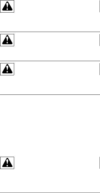
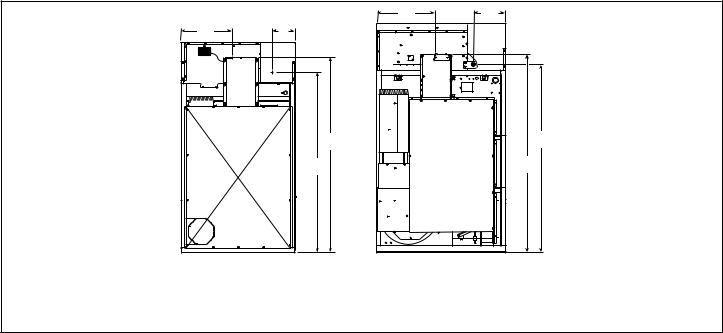
120 Series Tumble Dryer Dimensions and Exhaust Outlet Locations
|
|
1 |
W |
|
J |
|
|
I |
|
|
X |
|
V |
|
|
|
G |
|
|
H |
|
U |
K |
B |
|
|
|
|
|
A |
|
|
|
|
Y |
C |
|
Z |
D |
|
|
E |
|
F |
|
|
TMB2423N_SVG |
1. Top View of Exhaust Duct
Cabinet Dimensions
Models |
A |
B |
C |
D |
E |
|
|
|
|
|
|
120L/N/E |
31.38 in. [797 |
32.5 in. [826 mm] |
46.5 in. [1,181 |
49.91 in. [1,268 |
67.92 in. [1,725 |
|
mm] |
|
mm] |
mm] |
mm] |
|
|
|
|
|
|
120S |
31.38 in. [797 |
32.5 in. [826 mm] |
46.5 in. [1,181 |
49.91 in. [1,268 |
67.92 in. [1,725 |
|
mm] |
|
mm] |
mm] |
mm] |
|
|
|
|
|
|
Cabinet Dimensions
Models |
F |
G |
H |
I* |
J* |
K* |
|
|
|
|
|
|
|
120L/N/E |
46.38 in. [1,178 |
85.7 in. [2,177 |
70 in. [1,778 |
41.6 in. [1,057 |
43.2 in. [1,097 |
61.5 in. [1,562 |
|
mm] |
mm] |
mm] |
mm] |
mm] |
mm] |
|
|
|
|
|
|
|
120S |
46.38 in. [1,178 |
85.58 in. [2,174 |
70 in. [1,778 |
41.6 in. [1,057 |
43.2 in. [1,097 |
61.5 in. [1,562 |
|
mm] |
mm] |
mm] |
mm] |
mm] |
mm] |
|
|
|
|
|
|
|
* Fire suppression system optional - may not be on machine.
Refer to Position and Level the Tumble Dryer to temporarily reduce the heights of these models.
© Copyright, Alliance Laundry Systems LLC - |
16 |
Part No. 70458101ENR13 |
DO NOT COPY or TRANSMIT |
|
|
Specifications and Dimensions
Exhaust Outlet Dimensions and Locations
Models |
U |
V |
W |
X |
Y |
Z |
|
|
|
|
|
|
|
120L/N/E |
63.45 in. [1,612 |
8.44 in. [214 |
10 in. [254 |
8.18 in. [208 |
6.82 in. [173 |
8.18 in. [208 |
|
mm] |
mm] |
mm] |
mm] |
mm] |
mm] |
|
|
|
|
|
|
|
120S |
60.7 in. [1,542 |
8.44 in. [214 |
10 in. [254 |
8.18 in. [208 |
6.82 in. [173 |
8.18 in. [208 |
|
mm] |
mm] |
mm] |
mm] |
mm] |
mm] |
|
|
|
|
|
|
|
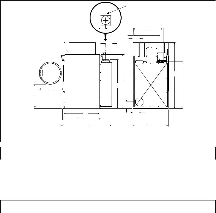
170 and 200 Series Tumble Dryer Dimensions and Exhaust Outlet Locations
1 |
X |
W |
H |
B |
A |
C |
D |
E |
1. Top View of Exhaust Duct
|
J |
I |
|
Y |
G |
|
K |
V |
|
|
F |
|
TMB2424N_SVG |
Cabinet Dimensions
Models |
A |
B |
C |
D |
E |
|
|
|
|
|
|
170L/N/S |
33.86 in. [860 |
32.5 in. [ 826 mm] |
48.33 in. [1,228 |
51.75 in. [1,314 |
68.85 in. [1,749 |
|
mm] |
|
mm] |
mm] |
mm] |
|
|
|
|
|
|
200L/N/S |
32.1 in. [815 mm] |
35.6 in. [ 904 mm] |
55.83 in. [1,418 |
59.25 in. [1,505 |
76.35 in. [1,939 |
|
|
|
mm] |
mm] |
mm] |
|
|
|
|
|
|
© Copyright, Alliance Laundry Systems LLC - |
17 |
Part No. 70458101ENR13 |
DO NOT COPY or TRANSMIT |
|
|
Specifications and Dimensions
Cabinet Dimensions
Models |
F |
G |
H |
I* |
J* |
K* |
|
|
|
|
|
|
|
170L/N/S |
53.12 in. [1,349 |
94 in. [2,388 |
75.12 in. [1,908 |
48.86 in. [1,241 |
50.45 in. [1,281 |
62.5 in. [1,588 |
|
mm] |
mm] |
mm] |
mm] |
mm] |
mm] |
|
|
|
|
|
|
|
200L/N/S |
53.12 in. [1,349 |
94 in. [2,388 |
75.12 in. [1,908 |
48.86 in. [1,241 |
50.45 in. [1,281 |
62.5 in. [1,588 |
|
mm] |
mm] |
mm] |
mm] |
mm] |
mm] |
|
|
|
|
|
|
|
* Fire suppression system optional - may not be on machine.
Refer to Position and Level the Tumble Dryer to temporarily reduce the heights of these models.
Exhaust Outlet Dimensions and Locations
Models |
V |
W |
X |
Y |
|
|
|
|
|
170L/N/S |
42.38 in. [1,076 mm] |
6.75 in. [171 mm] |
12 in. [305 mm] |
7 in. [178 mm] |
|
|
|
|
|
200L/N/S |
42.38 in. [1076 mm] |
6.75 in. [171 mm] |
12 in. [305 mm] |
7 in. [178 mm] |
|
|
|
|
|
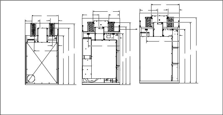
Electric and Gas Connection Locations for Gas Models Through 3/10/13
A |
C |
|
B |
|
D |
|
1 |
1.120L/N
2.170L/N
3.200L/N
A |
C |
|
D |
|
B |
|
2 |
|
TMB2255N_SVG |
A |
C |
B
D
3
TMB2382N_SVG
© Copyright, Alliance Laundry Systems LLC - |
18 |
Part No. 70458101ENR13 |
DO NOT COPY or TRANSMIT |
|
|
|
|
|
|
|
|
Specifications and Dimensions |
|
|
|
|
|
|
|
|
|
|
Electrical Connection |
Gas Connection |
|
|
|
||
|
|
|
|
|
|
|
|
Models |
A |
B |
C |
|
D |
|
Diameter |
|
|
|
|
|
|
|
|
120L/N |
18.34 in. [466 |
77.84 in. [1,977 |
12.5 in. [318 mm] |
|
70.5 in. [1,791 |
|
3/4 in. NPT |
|
mm] |
mm] |
|
|
mm] |
|
|
|
|
|
|
|
|
|
|
170L/N |
21 in. [533 mm] |
81 in. [2,057 mm] |
14.85 in. [377 |
|
77.4 in. [1,966 |
|
1 in. NPT |
|
|
|
mm] |
|
mm] |
|
|
|
|
|
|
|
|
|
|
200L/N |
21 in. [533 mm] |
81 in. [2,057 mm] |
13.7 in. [348 mm] |
|
77.4 in. [1,966 |
|
1 in. NPT |
|
|
|
|
|
mm] |
|
|
|
|
|
|
|
|
|
|
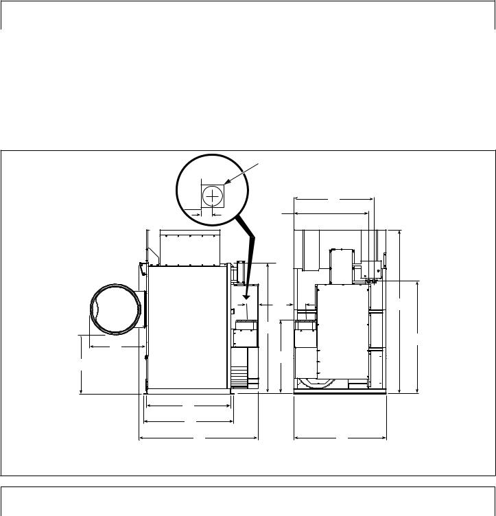
Electric and Gas Connection Locations for Gas Models Starting 3/11/13
A |
C |
|
B |
|
D |
|
1 |
1.120L/N
2.170L/N and 200L/N
A |
C |
|
D |
|
B |
|
2 |
|
TMB2400N_SVG |
|
Electrical Connection |
Gas Connection |
|
|
||
|
|
|
|
|
|
|
Models |
A |
B |
C |
|
D |
Diameter |
|
|
|
|
|
|
|
120L/N |
18.34 in. [466 |
77.84 in. [1,977 |
12.5 in. [318 mm] |
|
70.5 in. [1,791 |
1 in. NPT |
|
mm] |
mm] |
|
|
mm] |
|
|
|
|
|
|
|
|
170L/N |
21 in. [533 mm] |
81 in. [2,057 mm] |
14.85 in. [377 |
|
77.4 in. [1,966 |
1 in. NPT |
|
|
|
mm] |
|
mm] |
|
|
|
|
|
|
|
|
200L/N |
21 in. [533 mm] |
81 in. [2,057 mm] |
14.85 in. [377 |
|
77.4 in. [1,966 |
1 in. NPT |
|
|
|
mm] |
|
mm] |
|
|
|
|
|
|
|
|
© Copyright, Alliance Laundry Systems LLC - |
19 |
Part No. 70458101ENR13 |
DO NOT COPY or TRANSMIT |
|
|
Specifications and Dimensions
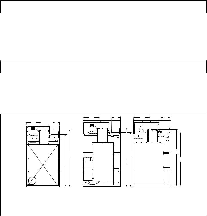
Electric and Steam Connection Locations for Steam Models Through 3/10/13
A1 |
A2 |
|
|
C |
|
|
|
B2 |
|
|
F |
B1 |
D |
E |
|
|
|
|
|
1 |
|
|
|
1.120S
2.170S
3.200S
C |
A1 |
A2 |
|
|
B2 |
|
B1 |
|
E F |
|
D |
|
2 |
|
TMB2401N_SVG |
|
A1 |
C |
A2 |
|
B2 |
|
B1 |
|
F |
|
E |
|
D |
|
3 |
|
TMB2383N_SVG |
|
Steam Inlet |
|
|
|
|
|
|
|
|
Models |
Diameter |
A1 |
A2 |
F |
|
|
|
|
|
120S |
3/4 in. NPT |
35.875 in. [911 mm] |
13.375 in. [340 mm] |
82.75 in. [2,102 mm] |
|
|
|
|
|
170S |
3/4 in. NPT |
37.625 in. [956 mm] |
15.25 in. [387 mm] |
88 in. [2,235 mm] |
|
|
|
|
|
200S |
3/4 in. NPT |
37.625 in. [956 mm] |
15.25 in. [387 mm] |
88 in. [2,235 mm] |
|
|
|
|
|
|
Steam Outlet |
|
|
|
|
|
|
|
|
Models |
Diameter |
B1 |
B2 |
D |
|
|
|
|
|
120S |
3/4 in. NPT |
34.625 in. [879 mm] |
13.125 in. [333 mm] |
68.5 in. [1,740 mm] |
|
|
|
|
|
170S |
1 in. NPT |
44.625 in. [1,133 mm] |
8.75 in. [222 mm] |
71.75 in. [1,822 mm] |
|
|
|
|
|
200S |
1 in. NPT |
44.625 in. [1,133 mm] |
8.75 in. [222 mm] |
71.75 in. [1,822 mm] |
|
|
|
|
|
© Copyright, Alliance Laundry Systems LLC - |
20 |
Part No. 70458101ENR13 |
DO NOT COPY or TRANSMIT |
|
|
|
|
Specifications and Dimensions |
|
|
|
|
Electrical Connection |
|
|
|
|
Models |
C |
E |
|
|
|
120S |
18.34 in. [466 mm] |
77.84 in. [1,977 mm] |
|
|
|
170S |
21 in. [533 mm] |
81 in. [2,057 mm] |
|
|
|
200S |
21 in. [533 mm] |
81 in. [2,057 mm] |
|
|
|
Electric and Steam Connection Locations for Steam Models Starting 3/11/13
A1 |
A2 |
|
|
C |
|
|
|
B2 |
|
|
F |
B1 |
D |
E |
|
|
|
|
|
1 |
|
|
|
1.120S
2.170S and 200S
C |
A1 |
A2 |
|
|
B2 |
|
B1 |
|
E F |
|
D |
|
2 |
|
TMB2401N_SVG |
|
Steam Inlet |
|
|
|
|
|
|
|
|
Models |
Diameter |
A1 |
A2 |
F |
|
|
|
|
|
120S |
3/4 in. NPT |
35.875 in. [911 mm] |
13.375 in. [340 mm] |
82.75 in. [2,102 mm] |
|
|
|
|
|
170S |
3/4 in. NPT |
37.625 in. [956 mm] |
15.5 in. [394 mm] |
87.625 in. [2,226 mm] |
|
|
|
|
|
200S |
3/4 in. NPT |
37.625 in. [956 mm] |
15.5 in. [394 mm] |
87.625 in. [2,226 mm] |
|
|
|
|
|
© Copyright, Alliance Laundry Systems LLC - |
21 |
Part No. 70458101ENR13 |
DO NOT COPY or TRANSMIT |
|
|
Specifications and Dimensions
|
Steam Outlet |
|
|
|
|
|
|
|
|
Models |
Diameter |
B1 |
B2 |
D |
|
|
|
|
|
120S |
3/4 in. NPT |
34.625 in. [879 mm] |
13.125 in. [333 mm] |
68.5 in. [1,740 mm] |
|
|
|
|
|
170S |
1 in. NPT |
44.125 in. [1,133 mm] |
9 in. [229 mm] |
72.125 in. [1,832 mm] |
|
|
|
|
|
200S |
1 in. NPT |
44.125 in. [1,133 mm] |
9 in. [229 mm] |
72.125 in. [1,832 mm] |
|
|
|
|
|
|
Electrical Connection |
|
|
|
|
Models |
C |
E |
|
|
|
120S |
18.34 in. [466 mm] |
77.84 in. [1,977 mm] |
|
|
|
170S |
21 in. [533 mm] |
81 in. [2,057 mm] |
|
|
|
200S |
21 in. [533 mm] |
81 in. [2,057 mm] |
|
|
|
© Copyright, Alliance Laundry Systems LLC - |
22 |
Part No. 70458101ENR13 |
DO NOT COPY or TRANSMIT |
|
|

Specifications and Dimensions
Electric Connection Location for Electric Models
A |
B |
TMB2336N_SVG |
Models |
A |
B |
|
|
|
120E |
35.81 in. [910 mm] |
85.64 in. [2,175 mm] |
|
|
|
© Copyright, Alliance Laundry Systems LLC - |
23 |
Part No. 70458101ENR13 |
DO NOT COPY or TRANSMIT |
|
|
Installation
Installation
Pre-Installation Inspection
Upon delivery, visually inspect the crate, carton and parts for any visible shipping damage. If the crate, carton, or cover is damaged or signs of possible damage are evident, have the carrier note the condition on the shipping papers before the shipping receipt is signed, or advise the carrier of the condition as soon as it is discovered.
Remove the crate and protective cover as soon as possible and check the items listed on the packing list. Advise the carrier of any damaged or missing articles as soon as possible. A written claim should be filed with the carrier immediately if articles are damaged or missing.
IMPORTANT: Remove the yellow shipping wire tie securing the airflow switch.
IMPORTANT: Warranty is void unless tumble dryer is installed according to instructions in this manual. Installation should comply with minimum specifications and requirements detailed in this manual and applicable local gas fitting regulations, municipal building codes, water supply regulations, electrical wiring regulations, and any other relevant statutory regulations. Due to varied requirements, applicable local codes should be thoroughly understood and all pre-installation work arranged for accordingly.
Materials Required (Obtain Locally)
|
All Models |
Circuit breaker on 3 Phase models. |
|
|
|
|
|
Table continues...
Materials Required (Obtain Locally)
Steam Models |
One steam shut-off valve for steam service |
|
line to be connected upstream of solenoid |
|
steam valve. |
|
Two steam shut-off valves for each conden- |
|
sate return line. |
|
Flexible steam hoses with a 125 psig |
|
[pounds per square inch gauge] [862 kPa] |
|
working pressure for connecting steam |
|
coils. Refer to Figure 21 and Figure 22 for |
|
sizing and connection configurations. |
|
Two steam traps for steam coil outlets to |
|
condensate return line. |
|
Optional – Two vacuum breakers for con- |
|
densate return lines. |
|
|
IMPORTANT: 3 Phase Only – Each tumble dryer must be connected to its own individual branch circuit breaker, not fuses, to avoid the possibility of “single phasing” and causing premature failure of the motor(s).
Location Requirements
The tumble dryer must be installed on a level floor. Floor covering materials such as carpeting or tile should be removed.
To assure compliance, consult local building code requirements. The tumble dryer must not be installed or stored in area where it will be exposed to water and/or weather.
IMPORTANT: DO NOT block the airflow at the rear of the tumble dryer with laundry or other articles. Doing so would prevent adequate air supply to the combustion chamber of the tumble dryer.
A typical tumble dryer enclosure is shown in Figure 2 .
IMPORTANT: Install tumble dryers with sufficient clearance for servicing and operation, refer to Figure 2 .
WARNING
To reduce the risk of severe injury, clearance of tumble dryer cabinet from combustible construction must conform to the minimum clearances, and/or local codes and ordinances.
W770R1
© Copyright, Alliance Laundry Systems LLC - |
24 |
Part No. 70458101ENR13 |
DO NOT COPY or TRANSMIT |
|
|

Installation
1 |
3 |
|
|
|
2 |
8 |
|
NOTE: Shaded areas indicate adjacent structure.
4 |
5 |
6 |
7 |
TMB2020N_SVG |
1.0 in. [0 mm] minimum, 0.5 in. [13 mm] recommended between machines for removal or installation
2.Allow 2-4 in. [51-100 mm] opening at top of machine to aid in removal or installation. A removable trim piece may be used to conceal the opening; zero clearance allowed for trim.
3.4 in. [100 mm] maximum header thickness
4.Minimum clearance permitted for remainder:
120 |
Gas/Electric |
4 in. [101.6 mm] |
|
|
|
120 |
Steam |
6 in. [152.4 mm] |
|
|
|
170/200 Gas |
4 in. [101.6 mm] |
|
|
|
|
170/200 Steam |
8 in. [203.2 mm] |
|
|
|
|
5.Guard
6.Provision for make-up air
7.24 in. [610 mm] minimum, 36 in. [914 mm] recommended for maintenance purposes
8.0 in. [0 mm] minimum, 0.25 in. [6 mm] recommended for removal or installation purposes
Figure 2
Position and Level the Tumble Dryer
The tumble dryer may be moved with or without the skid. To remove the skid, unscrew the four shipping bolts, and discard them.
Level the tumble dryer to within 0.13 inch [3.3 mm] from front- to-rear (level on cylinder rib), and side-to-side (level on upper access panel top surface). Shim under corners to level and stabilize unit. Tumble dryer must not rock.
To fit a 170 and 200 tumble dryer (with shipping skid) through a 8.0 foot [2.4 meters] high door, you must remove the front access panel. The upper 3.0 inches [76 mm] of the gas heater must also be removed on 170 gas tumble dryers. Removing the entire gas or steam heater assembly and the shipping skid, will reduce the height of the 120 tumble dryer to 70 inches [1,780 mm], and the 170 and 200 tumble dryer to 75 inches [1,910 mm].
Mounting
Where local code requires the unit to be securely mounted, use the shipping bolt frame holes found on the tumble dryer frame. Use either epoxy 3/8 in. [10 mm] bolts or equivalent 3/8 in. [10 mm] concrete anchors, such as expandable bolts.
© Copyright, Alliance Laundry Systems LLC - |
25 |
Part No. 70458101ENR13 |
DO NOT COPY or TRANSMIT |
|
|

Installation
Fire Suppression System (Optional
Equipment)
WARNING
ELECTRICAL SHOCK HAZARD. Electrical shock can result in death or serious injury. If the water dispensing system is activated, do not attempt to operate the tumble dryer. If the water dispensing system is activated, have the tumble dryer inspected by a qualified agency before operating the tumble dryer.
W879R1
IMPORTANT: Main supplies of electricity and water to the tumble dryer should remain on at all times for the fire suppression system to work.
Check Local Codes and Permits
Call your local water company or the proper municipal authority for information regarding local codes.
IMPORTANT: It is your responsibility to have ALL plumbing connections made by a qualified professional to assure that the plumbing is adequate and conforms to local, state, and federal regulations or codes.
IMPORTANT: It is the installation or owner’s responsibility to confirm that the necessary or required water, water pressure, pipe size, or connections are provided. Manufacturer assumes no responsibility if the fire suppression system is not connected, installed, or maintained properly.
Water Requirements
IMPORTANT: Water must be supplied to the fire suppression system, or the fire suppression system will not operate as intended.
To ensure the fire suppression system operates properly:
•Water supply requirements: 3/4 inch hose connections providing 15 gpm [57 lpm] minimum flow; Water pressure 20 psi
[138 kPa] minimum, 120 psi [827 kPa] maximum; water temperature 40°F [4.5°C] minimum, 120°F [49°C] maximum must be maintained at all times.
•Electric power to the tumble dryer must be provided at all times.
•Perform preventative maintenance checks every month. Refer to Operation/Maintenance Manual.
NOTE: Water pressure under 20 psi [138 kPa] will cause low flow at water solenoid valve.
If the rear of the tumble dryer or the water supply is located in an area where it will be exposed to cold/freezing temperatures, provisions must be made to protect these water lines from freezing.
IMPORTANT: Temperature of the water supply must be kept between 40°F and 120°F [4.5°C and 49°C]. If water in the supply line or water solenoid valve freezes, the fire suppression system will not operate.
IMPORTANT: If temperature sensors inside the tumble dryer register a temperature below 40F° [4.5°C], the fire suppression system control will lock out. This feature protects against operation of the tumble dryer with a possible frozen water supply. Only when the temperature sensors register a temperature above 40F° [4.5°C] will the machine reset for operation.
IMPORTANT: Flexible supply line/coupling must be used. Solenoid valve failure due to hard plumbing connections will void the warranty. It is recommended that a filter or strainer be installed in the water supply line.
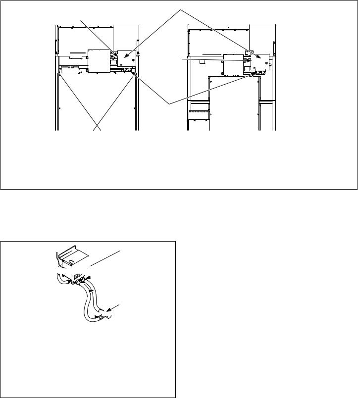
Water Connections
Connect machine to a backflow preventer (vacuum breaker) before connecting to the public water main in all countries where local regulations require specific water approval certificates.
Two hoses and a Y-valve are provided with the tumble dryer to allow for connection of water supply to tumble dryer. The water connections are made to the bushings of the water solenoid valve, located on the rear of the tumble dryer. The Y-valve provides a single female hose connection (Standard US 3/4-11 1/2 NH thread). Refer to Figure 3 and Figure 4 .
© Copyright, Alliance Laundry Systems LLC - |
26 |
Part No. 70458101ENR13 |
DO NOT COPY or TRANSMIT |
|
|
Installation
3 |
120 |
1
3 |
2
170/200
TMB2012N_SVG
1.Fire Suppression System Control Box
2.Water Solenoid Valve
3.Opening for Auxiliary Alarm Cable
Figure 3
To connect the two hoses (supplied with tumble dryer), insert rubber washers (from literature pack) in water inlet hose couplings. Refer to Figure 4 .

 1 5
1 5

 2
2
4
3
2 


TMB2008N_SVG
1.Lock
2.Hose Couplings
3.Y Valve
4.Inlet Hoses
5.Opening for Auxiliary Alarm Cable
Figure 4
Connect inlet hoses to water supply. Flush the lines for approximately two minutes to remove any foreign materials that could clog the screens in the water mixing valve. This is especially important when installing a tumble dryer in a newly constructed or
renovated building. Then connect the hoses to the Y-valve; connect the Y-valve to the connections at the rear of the tumble dryer.
IMPORTANT: Thread hose couplings onto valve connections finger tight, then turn 1/4 turn with pliers. Do not cross thread or overtighten couplings.
IMPORTANT: Hoses and other natural rubber parts deteriorate after extended use. Hoses may develop cracks, blisters or material wear from the temperature and constant high pressure they are subjected to. All hoses should be checked on a yearly basis for any visible signs of deterioration. Any hose showing the signs of deterioration listed above should be replaced immediately. All hoses should be replaced every five years.
NOTE: Longer inlet hoses are available (as optional equipment at extra cost) if the hoses supplied with the tumble dryer are not long enough for installation. Order hoses as follows:
Part No. 20617 Inlet hose 8 feet [2.44 m]
Part No. 20618 Inlet hose 10 feet [3.05 m]
NOTE: Replacement outlet hoses are available (at extra cost). Order 44073302 Hose, 21 in. [53 cm ] for 120 series and 44073303, 31 in. [79 cm] for 170 and 200 series.
© Copyright, Alliance Laundry Systems LLC - |
27 |
Part No. 70458101ENR13 |
DO NOT COPY or TRANSMIT |
|
|
Loading...