

UBIQUITI UBI UVC-G3-PRO Datasheet
1080p Indoor/Outdoor
IP Camera with Infrared
and Optical Zoom
Model: UVC-G3-PRO
Introduction
Thank you for purchasing the Ubiquiti Networks®
UniFi® Video G3 Pro Camera. This Quick Start
Guide is designed to guide you through
installation and also includes warranty terms.
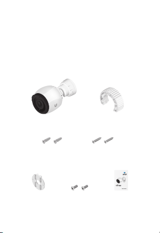
Package Contents
UVC-G3-PRO Tightening Tool
Screw Anchors
(Qty. 2)
Pole Mount
Bracket
Self-Tapping Screws
Machine Screws
(Qty. 2)
(Qty. 2)
1080p Indoor/Outdoor
IP Camera with Infrared
and Optical Zoom
Model: UVC-G3-PRO
Quick Start
Guide

Installation Requirements
• Pole-mounting: Two metal straps / hose
clamps (not included)
• Shielded Category 5 (or above) cabling with
drain wire should be used for all outdoor
wired Ethernet connections and should
be grounded through the AC ground of
the PoE.
We recommend that you protect
your networks from harmful outdoor
environments and destructive ESD events
with industrial-grade, shielded Ethernet
cable from Ubiquiti Networks. For more
details, visit www.ubnt.com/toughcable
• Surge protection should be used for all
outdoor installations. We recommend that
you use two Ethernet Surge Protectors,
model ETH-SP, one near the camera and the
other at the entry point to the building. The
ETH-SP will absorb power surges and safely
discharge them into the ground.
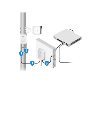
UVC-G3-PRO
US-8-150W
ETH-SP
ETH-SP
Diagram Showing Use of Ethernet Surge Protectors
TERMS OF USE: All Ethernet cabling runs must use CAT5 (or above).
Shielded Ethernet cable and earth grounding must be used for
outdoor installations as conditions of product warranty. TOUGHCable
is designed for outdoor installations. It is the professional installer’s
responsibility to follow local country regulations.
To LAN
™
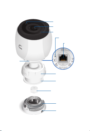
Hardware Overview
Camera
Ring
Ambient Light Sensor
Camera Lens
Microphone
Reset Button
Ethernet Port
Tilt/Mount Ring
Adjustable Base
Cable Gland
Mounting Base
Cable Slot

Ethernet 10/100 RJ45 port connects to an
802.3af/802.3at or 24V Passive PoE switch for
PoE power and data.
Reset Button To reset to factory defaults,
press and hold the Reset button for more than
10 seconds while the camera is poweredon.
Before You Begin
Remove the sticker from the bottom of the
Mounting Base.
Installation Overview
To install the camera, please follow the
instructions of the following sections in this
order:
1. Hardware Installation
2. Connecting Power over Ethernet
3. UniFi Video
4. Adjusting the Camera View
Hardware Installation
The camera can be mounted on a wall, ceiling,
or pole. Follow the appropriate steps for your
installation:
Wall/Ceiling Mount
1. Remove the Mounting Base from the
camera by turning the Tilt/Mount Ring
counterclockwise.
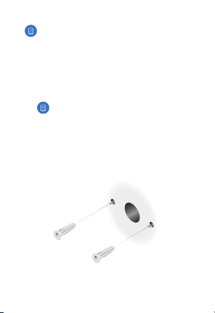
2. Mark the mounting holes on the wall or
ceiling.
Note: If you are running the cable along
the wall or ceiling, position the Cable
Slot towards the direction you want the
cabling to run. For outdoor installations,
position the Cable Slot downward.
3. Use a 7 mm (¼") drill bit to drill the
mounting holes in the wall or ceiling.
Note: If
you are running the Ethernet
cable through the wall, cut a hole
centered between the mounting
holes that is large enough to feed the
cable through.
4. Insert a Screw Anchor into each mounting
hole.
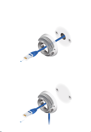
5. If you are feeding the Ethernet cable
through the wall or ceiling, do so now and
feed it through the Mounting Base.
If not, feed the Ethernet cable through the
Mounting Base and place the cable in the
Cable Slot.
IMPORTANT: If
camera outdoors, create a drip loop for
the cable below the camera to prevent
water ingress.
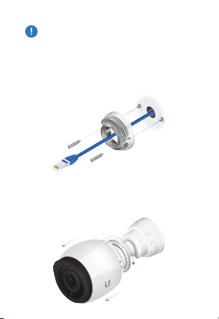
6. Fasten the Mounting Base to the wall or
ceiling using two Self-Tapping Screws.
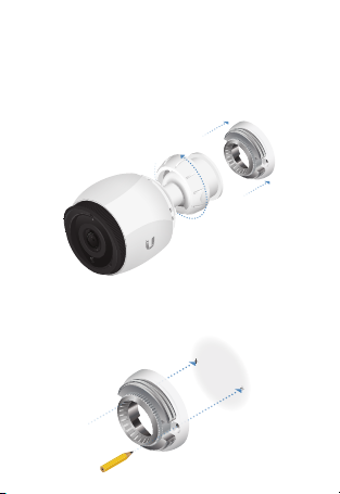
7. Remove the camera from the Adjustable
Base by turning the Camera Ring in the
direction shown.
you are installing your
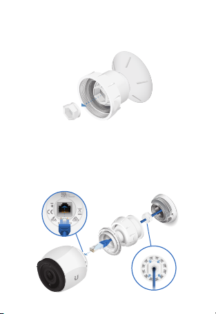
8. Remove the Cable Gland from the
Adjustable Base.
9. Feed the Ethernet cable through the Cable
Gland and Adjustable Base. Seal the Cable
Gland in place by firmly pressing around
its edges. Then connect the cable to the
Ethernet Port on the camera.
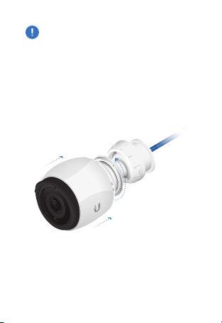
IMPORTANT: For proper weather sealing,
the Cable Gland must fit securely within
the Adjustable Base when the camera is
mounted. Ensure that the Cable Gland is
securely seated during installation and
cable routing.
10. Connect the camera back to the Adjustable
Base by turning the Camera Ring in the
direction shown.
 Loading...