


 Loading...
Power shower thermostatic
Installation and operating instructions
Installers please note these instructions are to be left with the user
The showerhead and hose supplied with this product are an integral part of the safety of your shower. Failure to use genuine Triton parts may cause injury and will invalidate your warranty
2180405O - January 2016

Power Shower Thermostatic
CONTENTS |
Page |
Plumbing and electrical notes......................................................... |
1 |
Introduction.................................................................................... |
2 |
Safety warnings............................................................................... |
2 |
Main components........................................................................... |
3 |
Specifications.................................................................................. |
3 |
Site requirements............................................................................ |
4 |
General installation notes................................................................ |
5 |
Siting of the shower........................................................................ |
6 |
Removing the cover........................................................................ |
7 |
Plumbing connections..................................................................... |
7 |
Fitting the shower to the wall........................................................ |
10 |
Electrical connections..................................................................... |
11 |
Commissioning.............................................................................. |
12 |
Temperature control spindle setting............................................... |
14 |
Operating the shower.................................................................... |
15 |
Adjusting the maximum temperature stop..................................... |
16 |
Instructions for installers and service engineers only....................... |
17 |
Spare parts..................................................................................... |
18 |
Fault finding................................................................................ |
19 - 20 |
Water/Cable entry points diagram..................................... |
21 |
Service policy, guarantee, etc.................................................... |
rear cover |
 WARNING
This appliance can be used by children aged from 8 years and above and persons with reduced physical, sensory or mental capabilities or lack of experience or knowledge if they have been
given supervision or instruction concerning use of the appliance.
in a safe way and understand the hazards involved. Children may not play with the appliance. Cleaning and user maintenance shall not be made by children without supervision.
To check the product suitability for commercial and multiple installations, please contact Triton’s speci cation advisory service before installation.
Telephone: 024 7637 2222
Facsimile: 024 7632 4504
E mail: technical@tritonshowers.co.uk

Power Shower Thermostatic
1 PLUMBING NOTES
1.1All installations must comply with Water Regulations or Water Bylaws.
1.2Supply pipes must be flushed to clear debris before connecting the shower unit.
1.3DO NOT connect the shower unit to the mains cold water supply as it would
damage the unit and also, the installation would be in breach of Water Regulations.
1.4DO NOT use excessive force when making connections to the flexible hose or showerhead – finger tight is sufficient.
1.5ALL plumbing connections are to be completed and water supplies turned on BEFORE switching on the electricity supply. The shower must not be operated dry without water.
1.6DO NOT solder pipes or fittings within 300 mm of the shower appliance, as heat transfer can damage components.
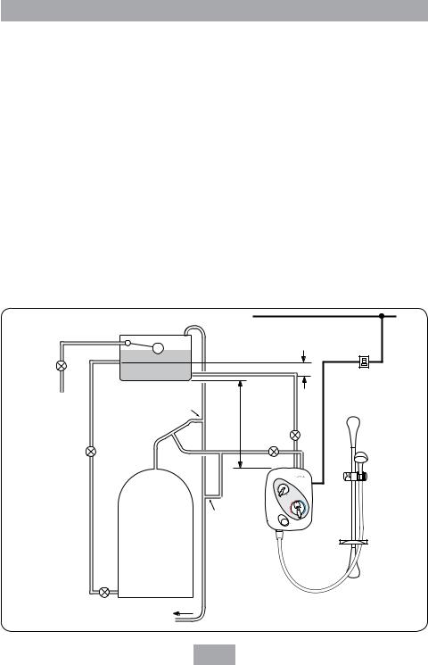
1.7When installed, the top of the shower unit must be at least 75 mm lower than the base of the cold water storage cistern to prevent the pump being run dry without water.
1.8A dedicated cold water supply must be taken directly from the cold water cistern to the shower. This draw-off must be on the opposite side of the cistern to the float operated valve to reduce the risk of air entering the unit.
1.9The action of the pump is to increase the flow rate. If the supply pipework cannot handle the resulting flow rate then:
1.9.1The anticipated flow rate may not be achieved.
1.9.2Air may be drawn into the hot supply from the vent pipe causing spluttering and temperature fluctuations at the showerhead.
1.10Fullway isolating valves MUST be fitted on the hot and cold water supplies to the shower as an independent means of isolating the water supplies should
maintenance or servicing be necessary. DO NOT use stop taps or ball-o-fix type valves which restrict flow.
2 ELECTRICAL NOTES
2.1The installation must comply with BS 7671 ‘Requirements for electrical installations’ (IEE wiring regulations). Make sure the incoming hot and cold water supplies to the shower are adequately earth bonded.
2.2DO NOT turn on the electrical supply until the plumbing connections have been
completed. Only then can the electricity be switched on in order to power the solenoid to turn water on to the shower when commissioning. The shower must not be operated dry without water.
2.3The mains supply must be 230/240V, at 50Hz, connected to the unit via a double pole switched 3 Amp fused connection unit (not supplied) with a minimum 3 mm contact separation gap in each pole.
2.4In accordance with ‘The Plugs and Sockets etc. (Safety) Regulations 1994’, this unit
is intended to be permanently connected to the fixed electrical wiring of the mains system.
2.5Fuses do not give personal protection against electric shock.
2.6A 30mA residual current device (RCD)
MUST be installed. This may be part of the consumer unit or a separate unit.
1

Power Shower Thermostatic
INTRODUCTION
This book contains all the necessary fitting and operating instructions for your Triton Power Shower. Please read them carefully.
The shower installation must be carried out by suitably competent person and in sequence of this instruction book.
Care taken during the installation will ensure a long and trouble free life from your shower
IMPORTANT: All plumbing connections must be completed BEFORE making the electrical connections.
Please read through the whole of this book before beginning your installation.
IMPORTANT: The fittings on the pipe inlet elbows are of the push-in type. The pipework must be cut with a pipe cutter and all burrs and rough edges removed from the end
of the tube. The fittings can be used with copper and plastic pipe.
Where chrome plated pipe is used, remove the first 25 mm of plating.
Note: The pump inside this product is rated 15 minutes on / 45 minutes off duty cycle.
SAFETY WARNINGS
a.DO NOT insert fingers into the push-in inlet fittings. Doing so could cause injury.
b.Under no circumstances must this product be connected to mains cold or hot water supplies. Failure to comply will invalidate the guarantee.
c.The shower MUST NOT be used if suspected of being frozen.
d.The outlet of this appliance MUST NOT be connected to any form of tap or fitting not recommended by the manufacturer.
e.The showerhead cartridge MUST be cleaned regularly to remove scale and debris.
f.This appliance MUST be earthed.
g.Switch off immediately at the isolating switch if water ceases to flow during use.
h.DO NOT operate the shower outside the guidelines laid out in ‘site requirements’.
Replacement parts can be ordered from Triton Customer Service. See ‘spare parts’ for details and part numbers.
A 30mA residual current device (RCD) MUST be installed in all UK 230V electric and pumped shower circuits. This may be part of the consumer unit or a separate unit.
2

Power Shower Thermostatic
MAIN COMPONENTS
1.Top pipe entry and cable entry
2.Terminal block
3.Cover screw fixing
4.Motor retaining bracket
5.Rear pipe entry and cable entry
6.Wall fixing holes
7.Pipe inlet elbow – top (contains single check valves)
8.Filter cover – top
9.Pump
10.PCB housing
11.Setting adaptor
12.Temperature control valve
13.Solenoid
14.Filter cover - bottom
15.Pipe inlet elbow – bottom (contains single check valves)
16.Outlet
17.Bottom pipe entry
|
1 |
|
Fig.1 |
|
|
|
|
4 |
3 |
|
|
|
2 |
|
|
|
|
|
86 |
|
|
3 |
mm |
|
5 |
|
|
|
6 |
|
|
|
7 |
6 |
|
|
|
|
|
|
8 |
|
268 |
|
|
|
|
|
|
|
mm |
9 |
11 |
|
|
|
|
|
|
|
|
10 |
|
13 |
12 |
|
|
|
|
|
|
6 |
14 |
|
|
|
|
|
|
|
6 |
|
|
|
15 |
|
|
|
3 |
|
|
16 |
17 |
56 mm |
|
|
|
82 mm
206 mm
SPECIFICATIONS
Hot water temperature
Maximum temperature 65°C.
BS 6700 recommends that the temperature of stored water should never exceed 65°C. A stored water temperature of 60°C is considered sufficient to meet all normal requirements and will minimise the effects of scale in hard water areas.
Temperature control
To obtain the maximum performance, this unit should be installed, operated and maintained as instructed in this book. The full performance specification as below for the unit is achieved with a blend set between 35°C – 40°C and supplies of 15°C cold and 65°C hot with nominally equal pressures.
1.The blended water temperature is maintained within 2°C with a 10°C change in the hot and cold water supply.
2.The sensor effects a shut down to seepage in about 2 seconds if the cold supply fails.
3.Shut down to seepage is achieved even if the hot supply is only 12°C above the blend temperature.
4.The blended water temperature is maintained within 1°C when the pressure between inlet and outlet is halved (defined as a pressure loss ratio of 2:1) on either the hot or cold side.
Maximum static inlet pressures
100 Kpa (1 bar) or 10m (supplies must be gravity fed at nominally equal pressures).
Minimum static inlet pressure
0.75 Kpa (0.0075 bar) or 75mm (required to prime the integral centrifugal pump).
Maximum supply head 10m.
3
Power Shower Thermostatic
SITE REQUIREMENTS
Water
The installation must be in accordance with Water Regulations/Bylaws and BS 6700.
For correct operation of this shower unit, both hot and cold water supplies to the appliance must be gravity fed, at nominally equal pressures, from a cold water storage cistern and a hot water storage cylinder.
The water circuit should be installed so that the flow is not significantly affected by other taps and appliances being operated elsewhere on the premises.
Fig.2 shows a recommended installation where the hot water supply for the shower is made via a tee connection on the underside of the
horizontal section of pipework from the cylinder. Alternatively, the connection can be taken from the hot supply pipe to other outlets as long as it is the first draw-off below the ventilation pipe tee.
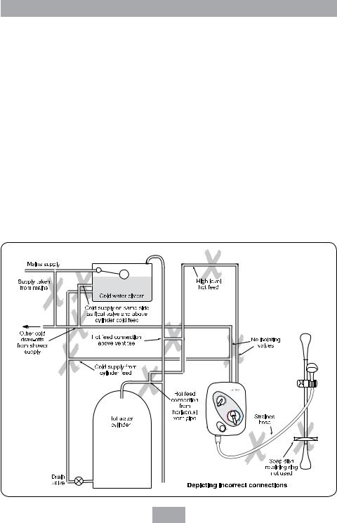
Fig.3 illustrates all the incorrect connections that must be avoided.
All pipework to the shower unit must be routed where it remains below the level of water in the cistern. In the case of horizontal sections
of pipework in lofts, it may be necessary to fit automatic air vents at high points on the supplies to remove the possibility of air locks.
For the operation of the shower only, it is recommended that the cold water storage cistern is capable of holding at least 114 litres (25 gallons). Where other hot and cold outlets are likely to be in use simultaneously, the storage capacity should be increased to 228 litres (50 gallons) in accordance with BS 6700.
Do ensure compliance with the Water Regulations/Bylaws.
DO NOT connect to a combination cylinder unless there is a guaranteed 114 litre cold supply to the cylinder as the shower can deliver up to 14 litres per minute. It is advisable to check that
|
|
|
|
|
Ring main |
|
Mains supply |
|
|
|
|
|
|
|
|
25 mm min |
|
Isolating |
|
|
|
|
|
valve |
|
Cold water cistern |
Dedicated cold supply |
Isolating spur |
|
|
|
|
|
||
|
|
|
|
|
(3A fused) |
|
|
|
|
|
outside bathroom |
|
|
Vent pipe tee |
10 m 75 mm |
|
|
|
|
max |
min |
|
|
|
|
|
|
||
|
|
|
|
Isolating |
|
|
Isolating |
|
|
valves |
|
|
|
|
|
|
|
|
valve |
Hot supply |
|
|
|
|
|
|
|
|
|
Alternative connection
Hot water |
Shower unit |
cylinder |
Drain
valve
Other hot water |
Fig.2 (Diagrammatic view – not to scale) |
draw-offs |
4
Power Shower Thermostatic
the infill rate from the float operated valve meets the output requirements..
It is recommended that there is a minimum of approximately 114 litres (25 gallons) of hot water storage per appliance.
The shower MUST NOT be connected to the mains cold water supply.
DO NOT use jointing compounds.
GENERAL INSTALLATION NOTES
1.DO NOT take risks with plumbing or electrical equipment.
2.DO NOT install this unit in a position where it could become frozen.
3.Isolate electrical and water supplies BEFORE proceeding with installation work.
4.Shower control MUST be fed from a cold water storage cistern and hot water cylinder that provides nominally equal pressures.
5.The unit must be mounted onto the finished wall surface (on top of tiles).
DO NOT tile up to the unit after fixing to the wall.
6.If installing with rear inlet supplies, it is recommended the supply pipework is sealed to the wall so as to prevent water from leaking back into the wall.
7.In solid wall installations, the supply pipework should be housed within ducting in order to allow some free lateral movement when making connections and to ensure compliance with requirements of accessibility of pipes and pipe fittings.
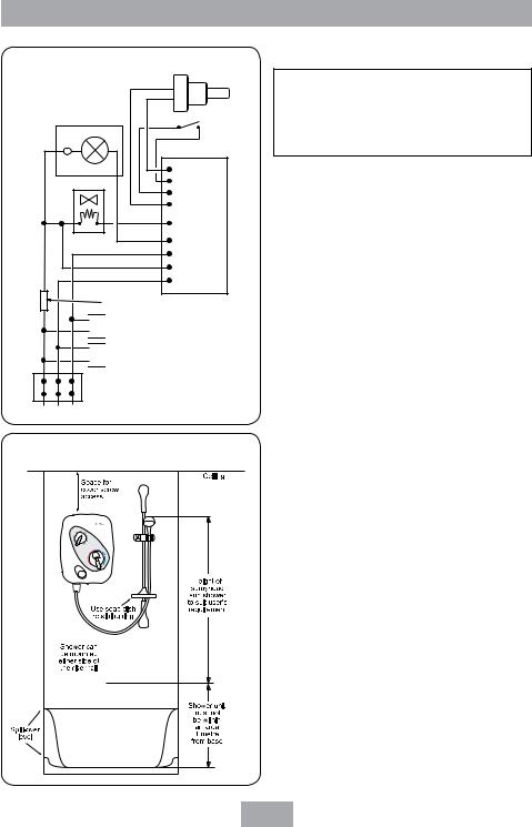
Fig.4 shows a schematic wiring diagram of the unit.
Fig.3 (Diagrammatic view not to scale)
5
Power Shower Thermostatic
Fig.4 |
(schematic view ) |
Potentiometer |
|
||
|
|
Switch |
|
Thermal |
|
|
fuse |
|
|
Motor |
|
|
|
PCB |
|
Solenoid |
|
|
RFI suppression coil |
|

 Capacitor 2

 Capacitor 1
L E N
Fig.5
SITING OF THE SHOWER
WARNING!
The shower must not be positioned where it will be subject to freezing conditions.
IMPORTANT: If fitting to a tiled wall, always mount the unit on the surface of the tiles. NEVER tile up to the unit.
Refer to fig.5 for correct siting of the shower. Position the unit vertically where it will NOT be in direct contact with water from the showerhead.
Note: Allow sufficient room between the ceiling and the shower unit to access the top cover screw.
Position the shower and showerhead on the wall so that all controls can be comfortably reached when using the shower.
The showerhead and riser rail can be positioned either side of the shower unit.
Note: Water Regulations require the showerhead be ‘constrained by a fixed or sliding attachment so that it can only discharge water at a point not less than 25 mm above the spill-over level of the relevant bath, shower tray or other fixed appliance’. The use of the supplied soap dish will in most cases meet this requirement, but if the showerhead can be placed within a bath, basin or shower tray, then a device must be fitted to prevent back-flow.
6
Loading...