


Madrid II electric shower
Installation and operating instructions
Installers please note these instructions are to be left with the user
The showerhead and hose supplied with this product are an integral part of the safety of your shower. Failure to use genuine Triton parts may cause injury and will invalidate your warranty
2180728H - Decmeber 2015

 INTRODUCTION - PLEASE READ
PLEASE READ THIS IMPORTANT SAFETY INFORMATION
Products manufactured by Triton are safe and without risk provided they are installed, used and maintained in good working order in accordance with our instructions and recommendations.
 WARNING: DO NOT operate shower if frozen, or suspected of being frozen. It must thaw out before using.
 DO NOT operate the unit if the showerhead or spray hose becomes damaged.
 DO NOT restrict flow out of shower by placing showerhead in direct contact with your body.
 DO NOT operate the shower if water ceases to flow during use or if water has entered inside the unit because of an incorrectly fitted cover.
 WARNING: If restarting the shower immediately after stopping, be aware that a slug of hot water will be expelled for the first few seconds.
This book contains all the necessary fitting and operating instructions for your electric shower. Care taken during the installation will provide a long, trouble-free life from your shower.
PLEASE READ THE GENERAL GUIDANCE NOTES BEFORE PROCEEDING.
Triton recommend watching the short online *videos that cover electric shower basics before your
installation - *(videos may not show the exact model purchased).
•What is an electric shower?
•Electrical requirements for electric showers
•Plumbing requirements for electric showers
•Kilowatt ratings explained
To view these videos visit: www.tritonshowers.co.uk/triton-products/product-videos.aspx
PLEASE USE THE FOLLOWING CHECK LIST TO AID YOUR INSTALLATION
SECTION
1
SECTION
2
SECTION
3
SECTION
4
SECTION
5
SECTION
6
SECTION
7
SECTION
8
SECTION
9
|
Tick off as |
|
you complete |
Check that the water supply will satisfy requirements (page 2 & 6).......................... |
1 |
Check that water & cable entry points of the unit meet requirements (page 3)........ |
2 |
Check that the electric supply will satisfy requirements (page 4 - 5).......................... |
3 |
Siting of the shower (page 6 - 7).............................................................................. |
4 |
Plumbing installation (page 8).................................................................................. |
5 |
Electrical installation (page 9)................................................................................... |
6 |
Fit to the wall & connect the shower supplies (page 9 - 11)..................................... |
7 |
Fitting the cover (page 12)....................................................................................... |
8 |
ONLY Commission the shower in the way described (page 13)........................... |
9 |
SECTION |
|
|
10 |
Familiarise yourself with the user operating instructions (page 14 - 16).................... |
10 |
|
2 |
|

IMPORTANT - GENERAL GUIDANCE NOTES |
1 GENERAL
1.1Isolate the electrical and water supplies before removing the cover.
1.2Read all of these instructions and retain them for later use.
1.3DO NOT take risks with plumbing or electrical equipment.
1.4Isolate electrical and water supplies before proceeding with the installation.
1.5The unit must be mounted onto the finished wall surface (on top of the tiles). DO NOT tile up to or seal around ANY PART of the unit using silicone sealer after fixing to the wall. Special care must be taken NOT TO BLOCK OR SEAL ANY PRD VENTS ON THE UNIT.
1.6Contact Customer Service (see back page), if any of the following occur:
a)If it is intended to operate the shower at pressures above the maximum or below the minimum stated.
b)If the unit shows a distinct change in performance.
c)If the shower is frozen.
1.7If it is intended to operate the shower in areas of hard water (above 200 ppm temporary hardness), a scale inhibitor may have to be fitted. For advice on the Scale Inhibitor, contact Customer Service.
1.8The showerhead must be cleaned regularly with descalent to remove scale and debris, otherwise restrictions to the flow on the outlet of the unit will result in higher temperatures and could also cause the (PRD) Pressure Relief Device in the unit to operate.
1.9This product is not suitable for mounting into steam rooms or steam cubicles.
2 PLUMBING
2.1The plumbing installation must comply with Water Regulations, Building Regulations or any particular regulations as specified by Local Water Company or Water Undertakers and should be in accordance with BS EN 806.
2.2The supply pipe must be flushed to clear debris before connecting to the shower unit.
2.3DO NOT solder pipes or fittings within 300mm of the shower unit, as heat can transfer along the pipework and damage components.
2.4DO NOT fit any form of outlet flow control as the outlet acts as a vent for the heater can.
2.5DO NOT use excessive force when making connections to the flexible hose or showerhead, finger tight is sufficient.
2.6All plumbing connections must be completed before making the electrical connections.
2.7This appliance MUST not be connected to the inlet supply by a hose-set.
3ELECTRICAL
3.1The installation must comply with BS 7671 ‘Requirements for electrical installations’ (IEE wiring regulations), building regulations or any particular regulations as specified by the local Electrical Supply Company.
3.2This appliance MUST be earthed.
3.3In accordance with ‘The Plugs and Sockets etc. (Safety) Regulations 1994’, this appliance is intended to be permanently connected to the fixed wiring of the electrical mains system.
3.4Make sure all electrical connections are tight to prevent overheating.
3.5A 30mA residual current device (RCD) MUST be installed in all UK electric and pumped shower circuits. This may be part of the consumer unit or a separate unit.
3.6Switch off immediately at isolating switch if water ceases to flow during use.
3.7Other electrical equipment i.e. extractor fans, pumps must not be connected to the circuits within the unit.
3.8Switch off at isolating switch when not in use. This is a safety procedure recommended with all electrical appliances.
3.9As with all electrical appliances it is recommended to have the shower and installation checked at least every two years by a competent electrician to ensure there is no deterioration due to age and usage.
 WARNING
This appliance can be used by children aged from 8 years and above and persons with reduced physical, sensory or mental capabilities or lack of experience or knowledge if they have been
given supervision or instruction concerning use of the appliance.
in a safe way and understand the hazards involved. Children may not play with the appliance. Cleaning and user maintenance shall not be made by children without supervision.

GENERAL ADVICE TO USERS
The following points will help you understand how the shower operates:
a.The electric heating elements operate at a constant rate at your chosen power setting. It is the rate of the water passing through the heater can which determines the water temperature. (The slower the flow, the hotter the water becomes; the faster the flow, the cooler the water).
b.During winter, the mains water supply will be cooler than in the summer. The flow rate will vary between seasons at any one temperature setting. At different times of the year you may have to adjust the position of the temperature control to maintain your desired temperature setting.
c.The stabiliser valve minimises variations in shower temperature during mains water pressure changes. If changes in shower temperature are experienced during normal use, it will most likely be caused by the water pressure falling near to or below the minimum level. The drop in pressure may be due to water being drawn off at other points in the house whilst the shower is in use. If pressure drops appreciably below the minimum, the heating elements will automatically cut out.
NOTE: If ever the water becomes too hot and you cannot obtain cooler water, first check that the sprayplate in the showerhead has not become blocked.
DO NOT place items such as soap or shampoo bottles on top of the unit. Liquid could seep through the joint between the cover and backplate.
IMPORTANT ADVICE TO USERS
 COMISSIONING ADVICE
When first installed the unit will be empty. It is essential the unit should contain water before the elements are switched on. It is vital that the commissioning procedure is followed. Failure to carry out this operation will result in damage to the unit and will invalidate the guarantee.
ADVISORY - CLEANING
It is recommended that all products are cleaned using warm, soapy water.
DO NOT use abrasive or aggressive chemical cleaning products as this may affect the product surface finish and invalidate your guarantee.
Please read this book thoroughly and familiarise yourself with all instructions before commencing installation and keep it for future reference.
The shower installation MUST be carried out by a suitably qualified person, in the sequence of this instruction book.

CONTENTS |
Page |
INTRODUCTION |
|
IMPORTANT SAFETY INFORMATION (please read) |
|
Installation check list (please follow & complete) |
|
GENERAL GUIDANCE NOTES |
|
GENERAL ADVICE TO USERS - CLEANING ADVICE |
|
SPECIFICATIONS............................................................................. |
2 |
DIMENSIONS & CABLE/WATER ENTRY POINTS............................... |
3 |
ELECTRICAL REQUIREMENTS........................................................ |
4 - 5 |
INSTALLING THE SHOWER................................................. |
6 - 12 |
Siting of the shower................................................................. |
6 - 7 |
Plumbing installation.................................................................. |
8 |
Electrical installation.................................................................... |
9 |
Fit to the wall & connect shower supplies.............................. |
9 - 11 |
Fitting the cover......................................................................... |
12 |
COMMISSIONING PROCEDURE.......................................... |
13 |
USER OPERATING INSTRUCTIONS..................................... |
14 - 16 |
Operating functions....................................................................... |
16 |
Cleaning the filter - installers & service engineers only.................... |
17 |
Fault finding/Troubleshooting.................................................... |
18 - 19 |
Spare parts..................................................................................... |
20 |
SHOWER CONTROLS - QUICK USER GUIDE................ |
Inside rear cover |
UK Service Policy/UK Guarantee............................................... |
Rear cover |
To check the product suitability for commercial and multiple installations, please contact Triton’s speci cation advisory service before installation.
Telephone: 024 7637 2222
Facsimile: 024 7632 4504
E mail: technical@tritonshowers.co.uk
1

SECTION |
|
|
|
1 |
check list |
SPECIFICATIONS |
|
|
|
|
|
|
|
ELECTRICAL |
|
|
|
|
|
Nominal power - rating at 240V |
|
Nominal power - rating at 230V |
|
|
|
|
|
8.5kW – (40A MCB rating) |
|
7.8kW – (40A MCB rating) |
|
|
|
|
|
9.5kW – (40A MCB rating) |
|
8.7kW – (40A MCB rating) |
|
|
|
|
|
10.5kW – (45A MCB rating) |
|
9.6kW – (45A MCB rating) |
|
|
|
|
|
|
PLUMBING (see page 6 & 7 for water regulations) |
||
|
|
|
|
Supply Source |
|
Mains pressure cold water only |
|
|
|
||
Minimum running pressure and flow to the inlet |
100kPa (1.0 bar) at 8 litres per minute for |
||
of the shower for full performance |
7.5Kw & 8.5Kw |
||
|
|
|
|
|
|
|
150kPa (1.5 bar) at 11 litres per minute for 10.5kW |
|
|
|
|
Maximum static pressure |
|
1000 kPa (10 bar) |
|
|
|
|
|
Maximum inlet temperature |
|
28°C |
|
|
|
|
|
Minimum inlet temperature |
|
2°C |
|
|
|
|
|
Inlet connection |
|
15mm diameter |
|
|
|
|
|
Outlet connection |
|
½” BSP male thread |
|
|
|
|
|
|
|
MATERIALS |
|
|
|
|
|
ABS |
|
|
Backplate, cover, controls, showerhead |
|
|
|
|
Acetal |
|
|
Sprayplate |
|
|
||
Minerally insulated corrosion resistant metal |
Elements |
||
sheathing |
|
|
|
|
|
|
|
|
|
STANDARDS and APPROVALS |
|
|
|
|
|
Splashproof rating |
|
IPX4 |
|
|
|
|
|
Safety |
|
|
Complies with the requirements of current |
|
|
|
British and European safety standards for |
|
|
|
household and similar electrical appliances |
|
|
|
|
BEAB |
|
|
Complies with requirements of the British |
|
|
|
Electrotechnical Approvals Board (BEAB) |
|
|
|
|
CE |
|
|
Meets with Compliance with European |
|
|
|
Community Directives (CE) |
|
|
|
|
2

|
SECTION |
DIMENSIONS & ENTRY POINTS |
check list 2 |
Fig.1 |
DIMENSIONS |
210mm |
110mm |
305mm
|
|
ENTRY POINTS |
WATER |
= Back |
= Others |
Left: Side, Top.
Right: Bottom, Side & Back.
CABLE  = Back
  = Others
Left: Top, Bottom, Side & back.
Right: SIde.
PLEASE NOTE: Deviation from the approved entry points will invalidate product specifications and warranty.
Fig.2
3
SECTION |
|
|
|
3 |
check list |
ELECTRICAL REQUIREMENTS |
|
ELECTRICAL REQUIREMENTS |
Triton Showers, |
||
|
|
Fig.3 |
|
|
|
|
Triton Road, Nuneaton, |
|
ARNING! |
|
Warwickshire, CV11 4NR |
|
W-006-A |
|
xxxx |
|
THIS APPLIANCE MUST BE EARTHED |
||
The installation, supply cable and circuit protection must conform with BS 7671 (IEE wiring regulations) and be suf cient for the amperage required.
The following notes are for guidance only: 1
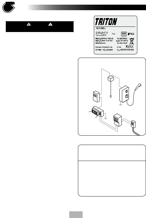
1.1The electrical rating of the shower is shown on the rating label (Fig.3) within the unit.
2Before making any sort of electrical connection within the installation make sure that no terminal is live. If in any doubt, switch off the whole installation at the mains supply and remove the correct fuse.
3The shower must be connected to its own independent electrical circuit. IT MUST NOT be connected to a ring main, spur, socket outlet, lighting circuit or cooker circuit.
3.1The electrical supply must be adequate for the loading of the unit and existing circuits.
4Check your consumer unit (main fuse box) has a main switch rating of 80A or above and that it has a spare fuse way which will take the fuse or Miniature Circuit Breaker (MCB) necessary for the shower (Fig.4).
4.1If your consumer unit has a rating below 80A or if there is no spare fuse way, then the installation will not be straightforward and may require a new consumer unit serving the house or just the shower.
4.2You will need to contact the local electricity company. They will check the supply and carry out what is necessary.
5For close circuit protection DO NOT use a rewireable fuse. Instead use a suitably rated Miniature Circuit Breaker (MCB) or cartridge fuse (see Table A).
5.1A 30mA residual current device (RCD) MUST be installed in all UK electric and pumped shower circuits. This may be part of the consumer unit or a separate unit.
Fig.4 Schematic of installation circuit
|
Pull cord |
|
|
isolating switch |
|
RCD |
Shower |
|
unit |
||
(can be part of |
||
consumer unit) |
|
Fuse or |
Consumer |
|
|
|
unit |
Meter |
|
||
MCB |
Incoming |
|||
|
||||
|
|
|
supply |
|
80A or 100A |
|
|
fuse |
|
main switch |
|
|
|
|
|
Meter |
|
|
|
|
tails |
|
|
|
|
Table A |
|
||
CIRCUIT PROTECTION |
||||
unit |
|
|
cartridge |
|
rating |
MCB |
fuse |
||
7.0kW |
30/32A |
30A |
||
7.5kW |
32A |
|
35A |
|
8.0kW |
40A |
|
35A |
|
8.5kW |
40A |
|
45A |
|
9.0kW |
40A |
|
45A |
|
9.5kW |
40/45A |
45A |
||
10.5kW |
45A |
|
45A |
|
4
6A 45 amp double pole isolating switch with a minimum contact gap of 3 mm in both poles must be incorporated in the circuit.
6.1It must have a mechanical indicator showing when the switch is in the OFF position, and the wiring must be connected to the switch without the use of a plug or socket outlet.
6.2The switch must be accessible and clearly
 able, but out of reach of a person
u xed bath or shower, except for the cord of a cord operated switch, and should be placed so that it is not possible to touch the switch body while standing in a bath or shower cubicle. It should be readily accessible to switch off after using the shower.
7Where shower cubicles are located in any rooms other than bathrooms, all socket outlets in those rooms must be protected by a 30mA RCD.
8The current carrying capacity of the cable must be at least that of the shower circuit protection (see Table B).
8.1To obtain full advantage of the power provided by the shower, use the shortest cable route possible from the consumer unit to the shower.
8.2It is also necessary to satisfy the disconnection time and thermal constraints which means that for any given combination of current demand, voltage drop and cable size, there is a maximum permissible circuit length.
9The shower circuit should be separated from other circuits by at least twice the diameter of the cable or conduit.
9.1The current rating will be reduced if the cabling is bunched with others, surrounded by thermal loft or wall insulation or placed in areas where the ambient temperature
is above 30°C. Under these conditions, derating factors apply and it is necessary to select a larger cable size.
9.2In the majority of installations (see Table B), the cable will unavoidably be placed in one or more of the above conditions. This being so, it is strongly
recommended to use a minimum of 10mm cabling throughout the shower installation.
SECTION
Continued 3
9.3In any event, it is essential that individual site conditions are assessed by a competent electrician in order to determine the correct cable size and permissible circuit length.
Table B
Twin and earth PVC insulated cable Current carrying capacity
|
|
Clipped direct |
|
|
or buried in a |
Installed in an |
In conduit |
non-insulated |
insulated wall |
trunking |
wall |
6mm² |
6mm² |
6mm² |
32A |
38A |
46A |
10mm² |
10mm² |
10mm² |
43A |
52A |
63A |
16mm² |
16mm² |
16mm² |
57A |
69A |
85A |
Note: Cable selection is dependent on derating factors
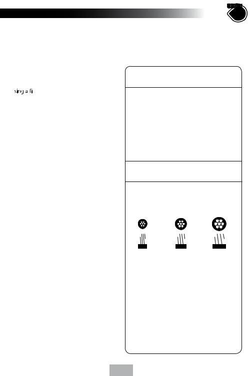
*The method below may be used by installers to determine the approximate size of the incoming cable.
6mm2 |
10mm2 |
16mm2 |
||||||||||||
|
|
|
|
|
|
|
|
|
|
|
|
|
|
|
|
|
|
|
|
|
|
|
|
|
|
|
|
|
|
|
|
|
|
|
|
|
|
|
|
|
|
|
|
|
|
|
|
|
|
|
|
|
|
|
|
|
|
|
|
1.Measure the width of an individual strand, and half that measurment to find (r),
e.g: 1.34mm ÷ 2 = (r) 0.67mm
2.Multiply (r) x (r) x 3.14,
e.g: (r) 0.67 x (r) 0.67 x 3.14 = 1.41mm2
3.Multiply this by the number of wire strands (usually 7), e.g: 1.41mm2 x 7 = 9.87mm2.
4.The number obtained would suggest 10mm2 wiring.
*PLEASE NOTE: If unsure, consult a qualified Electrician.
5
 Loading...