How it Works
Log In / Sign Up
Buy Points
How it Works
FAQ
Contact Us
Questions and Suggestions
Users
Triton
Loading...
T
t150z
T20 AD
T20CH
2
T20 DD
T20ID
2
T22i
T300si
2
T30i
T40I
T41200BS
2
T550i
T70gsi Plus
T70si
T80 Easi-fit
2
T80 GSI
T80 PRO-FIT
T80si
T80Z
3
T80Z SLIMLINE
T90SR
T90xr
TA1200BS
2
TA184CSL
2
TA 235CSL
4
TAMAS
TargetPro
TAS2000SR
TBJ001
2
TC12DBSMS
TCB 100
TCM BS
2
TCM PL
2
TCROS 4.5 Amps
TDJ 600
4
TDL Gateway Modem
TDPS200T
TDPS200TSAT
TGA 001
TGA 150
TGA250
TGEOS
2
Thames
3
Thiago
TJS 001
TLS
TMUTL
Topaz T100si
Topaz T80si
TPB2-83
TPL 180
3
TPT 125
4
TRA001
6
TRBS12
TRIT001-US
TROS 125
2
TRPUL
3
TRTA001
TSA001
2
TSPS370
TSPS 450
5
TSPSP650
TSPST 450
3
TTN-HDS-1602
TTS 1400
6
TTSTS
TW10i
TWSMPJ
TW SS10
3
TWX7
5
TWX7 CS001
3
TWX7PS001
TWX7RT001
3
Tyne
V
V575W
VALDI
W
WALLY-OK7Q
WCA201
2
WCA390
2
WRA 001
X
XML
X-SCALE-X2
XT
XT18
4
XT18DD2BS
XT 2500G
XT3AHB
XTRJSB
Z
Zante 3
Zante 4
Loading...
Loading...
Nothing found
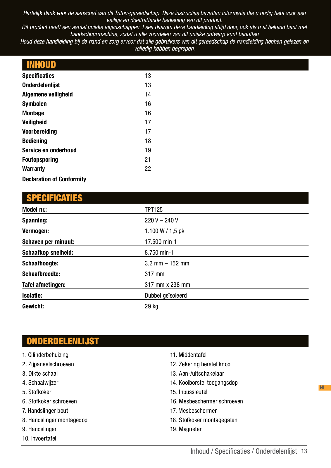
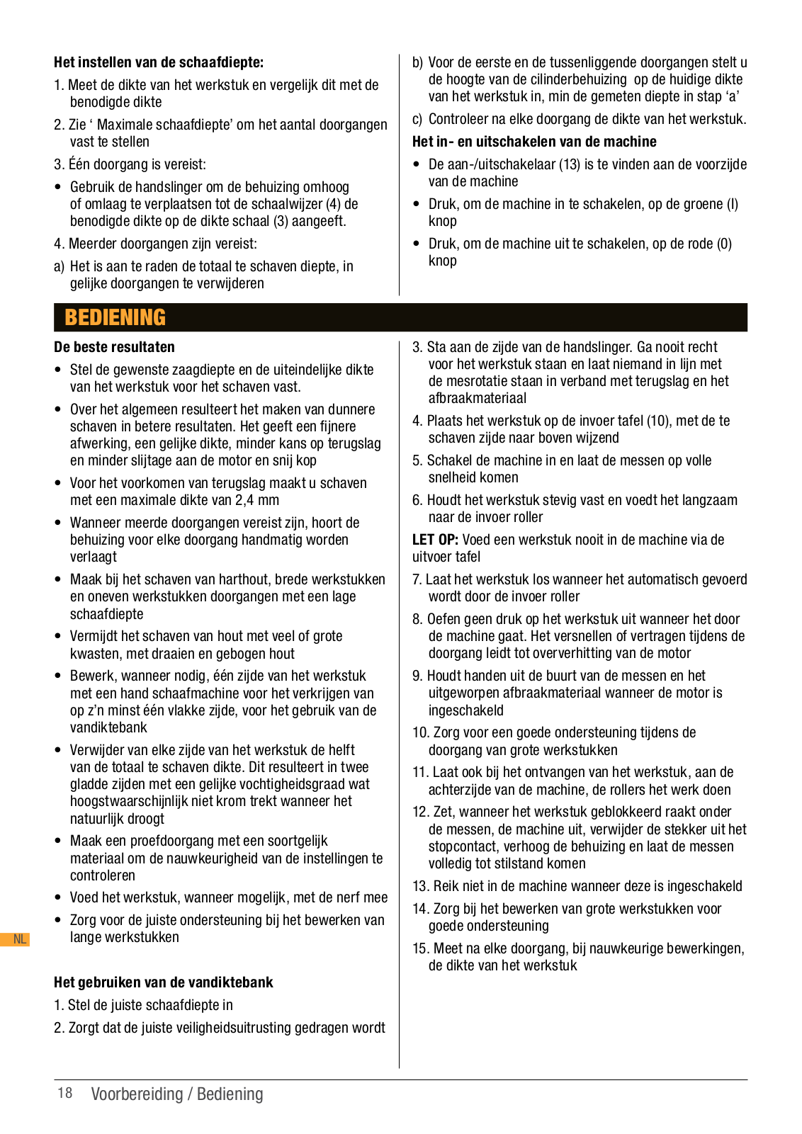
TPT 125
Operating And Safety Instructions Manual
110 pgs
6.23 Mb
0
Operating/safety Instructions Manual
44 pgs
3.25 Mb
0
User Manual [de]
2 pgs
183.05 Kb
0
User Manual [en, de, es, fr, it]
64 pgs
1.61 Mb
1
Table of contents
Loading...
Triton TPT 125 User Manual [en, de, es, fr, it]
...
Triton User Manual [en, de, es, fr, it]
Download
Specifications and Main Features
Frequently Asked Questions
User Manual
Download
Loading...
+
hidden pages
Unhide
You need points to download manuals.
1 point = 1 manual.
You can buy points or you can get point for every manual you upload.
Buy points
Upload your manuals