


Saw Table |
|
|
100 |
|
|
TCB |
|||
|
|
|
||
Operating and |
Gebrauchsund |
|||
Safety Instructions |
Sicherheitsanweisung |
|||
Bedieningsen |
Istruzioni Per L’uso E |
|||
La Sicurezza |
||||
veiligheidsvoorschriften |
||||
|
|
|
||
Instructions d’utilisation et |
Instrucciones de uso y |
|||
de seguridad |
||||
consignes de sécurité |
||||
|
|
|
||
www.tritontools.com

Thank you for purchasing this Triton tool. These instructions contain information necessary for safe and effective operation of this product.
This product has a number of unique features. Even if you are familiar with this Workcentre, please read this manual to make sure you get the full benefit of its unique design.
Keep this manual close to hand and ensure all users of this tool have read and fully understood the instructions.
CONTENTS
Specifications |
2 |
Symbols |
2 |
Parts List |
3 |
Safety |
4 |
Assembly |
5 |
Warranty |
13 |
SPECIFICATIONS
Part no: |
TCB100 |
Suits: |
Most circular saws (185mm - 235mm) |
Cuts: |
Rip, mitre, crosscut, |
Rip capacity: |
0 - 450mm |
Crosscut capacity: |
Up to 450mm wide |
Standing size: |
980mm x 380mm x 1040mm approx |
Folded size: |
900mm x 540mm x 300mm approx |
Standard features: |
Rip fence with 0-450mm capacity, See-through guard, anti- |
|
kickback finger & dust extraction port, Intergrated pushstick & |
|
side pressure fingers |
Optional Accessory Range: |
Bevel ripping guide, dust collection bucket, dust bag |
Protect your hearing |
|
Always use proper hearing protection when tool noise exceeds 85dB.
SYMBOLS
ENVIRONMENTAL PROTECTION
Waste electrical products should not be disposed of with household waste. Please recycle where facilities exist. Check with your local authority or retailer for ecycling advice.
GB
Always wear ear, eye and respiratory protection.
Double insulated for additional protection.
 Instruction warning.
Do not use before viewing and understanding the full operating instructions
2 Contents / Specifications / Symbols

PARTS LIST
A. Main Body (1) |
B. |
Rear Legs (2) |
|
C. |
Front Legs (2) |
|
D. |
Rip Fence (1) |
E. Captive Push-Stick (1) |
F. Protractor (1) |
G+H. Overhead Guard Support (1) |
FASTENER BAG
I. M6 x 40mm |
O. Saw Back Stop (1) |
|
Coach Bolt (4) |
||
|
||
J. Washer (5) |
|
|
K. M6 Flange Nut (5) |
P. Trigger Strap (1) |
|
|
||
L. M6 x 12mm |
Q. Storage Hook (2) |
|
Coach Bolt (1) |
|
|
M. Clamp Knob (4) |
|
|
|
R. Temporary Saw Clamp (4) |
|
N. Clamp Base (4) |
|
GB
Parts List 3

GENERAL SAFETY INSTRUCTIONS
WARNING Read all safety warnings and all instructions. Failure to follow the warnings and instructions may result in electric shock, fire and/
or serious injury.
Save all warnings and instructions for future reference.
The term "power tool" in the warnings refers to your mains-operated (corded) power tool or batteryoperated (cordless) power tool.
1) Work area safety
a)Keep work area clean and well lit. Cluttered or dark areas invite accidents.
b)Do not operate power tools in explosive atmospheres, such as in the presence of flammable liquids, gases or dust. Power tools create sparks which may ignite the dust or fumes.
c)Keep children and bystanders away while operating a power tool. Distractions can cause you to lose control.
2) Electrical safety
a)Power tool plugs must match the outlet. Never modify the plug in any way. Do not use any adapter plugs with earthed (grounded) power tools. Unmodified plugs and matching outlets will reduce risk of electric shock.
b)Avoid body contact with earthed or grounded surfaces, such as pipes, radiators, ranges and refrigerators. There is an increased risk of electric shock if your body is earthed or grounded.
c)Do not expose power tools to rain or wet conditions. Water entering a power tool will increase the risk of electric shock.
d)Do not abuse the cord. Never use the cord for carrying, pulling or unplugging the power tool. Keep cord away from heat, oil, sharp edges or moving parts. Damaged or entangled cords increase the risk of electric shock.
e)When operating a power tool outdoors, use an extension cord suitable for outdoor use. Use of a cord suitable for outdoor use reduces the risk of electric shock.
f)If operating a power tool in a damp location is unavoidable, use a residual current device (RCD)
GB protected supply. Use of an RCD reduces the risk of electric shock.
NOTE: The term “residual current device (RCD)” may be replaced by the term “ground fault circuit interrupter (GFCI)” or “earth leakage circuit breaker (ELCB)”.
3) Personal safety
a)Stay alert, watch what you are doing and use common sense when operating a power tool. Do not use a power tool while you are tired or under the influence of drugs, alcohol or medication. A moment of inattention while operating power tools may result in serious personal injury.
b)Use personal protective equipment. Always wear eye protection. Protective equipment such as dust mask, non-skid safety shoes, hard hat, or hearing protection used for appropriate conditions will reduce personal injuries.
c)Prevent unintentional starting. Ensure the switch is in the off-position before connecting to power source and/or battery pack, picking up or carrying the tool. Carrying power tools with your finger on the switch or energising power tools that have the switch on invites accidents.
d)Remove any adjusting key or wrench before turning the power tool on. A wrench or a key left attached to a rotating part of the power tool may result in personal injury.
e)Do not overreach. Keep proper footing and balance at all times. This enables better control of the power tool in unexpected situations.
f)Dress properly. Do not wear loose clothing or jewellery. Keep your hair, clothing and gloves away from moving parts. Loose clothes, jewellery or
long hair can be caught in moving parts.
g)If devices are provided for the connection of dust extraction and collection facilities, ensure these are connected and properly used. Use of dust collection can reduce dust-related hazards.
4) Power tool use and care
a)Do not force the power tool. Use the correct power tool for your application. The correct power tool will do the job better and safer at the rate for which it was designed.
b)Do not use the power tool if the switch does not turn it on and off. Any power tool that cannot be controlled with the switch is dangerous and must be repaired.
c)Disconnect the plug from the power source and/ or the battery pack from the power tool before making any adjustments, changing accessories, or storing power tools. Such preventive safety measures reduce the risk of starting the power tool accidentally.
d)Store idle power tools out of the reach of children and do not allow persons unfamiliar with the power tool or these instructions to operate the power tool.Power tools are dangerous in the hands of untrained users.
4 |
General Safety Instructions |

e)Maintain power tools. Check for misalignment or binding of moving parts, breakage of parts and any other condition that may affect the power tool’s operation. If damaged, have the power tool repaired before use. Many accidents are caused by poorly maintained power tools.
f)Keep cutting tools sharp and clean. Properly maintained cutting tools with sharp cutting edges are less likely to bind and are easier to control.
ASSEMBLY
g)Use the power tool, accessories and tool bits etc. in accordance with these instructions, taking into account the working conditions and the work to be performed. Use of the power tool for operations different from those intended could result in a hazardous situation.
5) Service
a)Have your power tool serviced by a qualified repair person using only identical replacement parts.
This will ensure that the safety of the power tool is maintained.
UNPACKING
•Carefully unpack and check that all items are included and in good condition
•If any items are missing or damaged, do not use this tool. Return it to your retailer
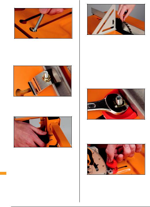
FITTING THE RIP FENCE
Fully raise the Fence Clamp Handles on the end panels. Unfold the arms of the Rip Fence (D) and slide it along the fence tracks from the right hand side of the unit (when viewed from the front panel, which has the switchbox). Note that the taller part of the fence is facing the plastic insert in the tabletop (Fig 1).
Fig 1
Study the Fence Scale Pointers. The rip fence can be fitted on the right or left hand side of the blade,
depending on the cut you are making or your personal preference.
The 2.5mm calibration notch means that the scales will be accurate on either side of the blade, provided your saw has a standard width of cut (kerf) of 2.5mm Use either side of the notch, depending on which side your fence is set, to line up with the calibration scales on the Fence Arms.
NOTE: If your saw has a very thin slitting blade, read ‘Using Thin Blades’ in ‘Troubleshooting’.
Fig 2
With the fence on the right-hand side, align the side of the notch closest to the fence with the ‘0’ on the scales (Fig 2). Depress the black plastic fence locking levers at the front and rear panels to lock the fence in that position.
Use an accurate set square to check the vertical face of the rip fence is exactly square to the table at both ends. If necessary, you can tilt the fence using the jacking screws (Fig 3).
If you are making any significant adjustments, you will need to slide the fence clear of the table and loosen or tighten the pivot bolts attaching the fence arms. The arms must pivot firmly but freely, without wobbling.
|
Fig 3 |
|
|
|
|
|
|
TEMPORARY SAW FITTING |
|
||
Turn the Main Body (A) upside down and rest it on a |
|
||
table or bench, with the fence overhanging the edge. |
|
||
Alternatively, place the unit on wooden packers thick |
|
||
enough to allow your saw blade, at maximum depth of |
|
||
cut, to fit through the slot in the table. |
|
||
With your saw disconnected from power, lock the |
|
||
blade at full depth of cut and check that the blade is |
|
||
set at 0° on the saw’s angle adjuster. |
|
||
Pull back the saw’s safety guard and, with the front of |
|
||
the saw facing the switch box, lower the blade through |
|
||
the slot. |
|
||
|
|
|
|
NOTE: The slot is sized for a 235mm (9 ¼”) blade. If |
GB |
||
|
|||
you have a smaller saw, slide it backwards until the |
|
||
back of the blade is approx 10mm from the rear end |
|
||
of the slot. If your blade does not fit the slot, refer to |
|
||
‘Troubleshooting – Saw Fitting Problems’. |
|
||
Choose the four keyhole slots which provide the |
|
||
best clamping positions for your saw. If you have a |
|
||
choice of slots, select those that are as far apart as |
|
||
possible lengthways along the base plate. Try to avoid |
|
||
General Safety Instructions / Assembly |
5 |
obstructions on the saw, such as raised sections of the base plate or the saw’s height adjustment lever.
Fig 4
Remove the saw and fit the four long Coach Bolts (I), with Washers (J) under their heads as shown (Fig 4), into the selected slots.
Replace the saw, with the blade touching the fence. Firmly finger-tighten the Temporary Saw Clamps (R) onto the coach bolts using the Flange Nuts (K). See Fig 5, below.
Fig 5
FITTING THE LEGS
Plug the Rear Legs (B) fully into their housings at the rear of the unit. Plug the uncapped ends of the Front Legs (C) in the front panel sockets. Lock them by tightening the round knobs (Fig 6).
Fig 6
NOTE: There may be cracking noises as the powder coat seal breaks – this is normal.
Turn the saw table right way up and test that all four feet are square on the ground. Adjust as necessary by extending one of the legs slightly from its housing until unit is stable.
GB
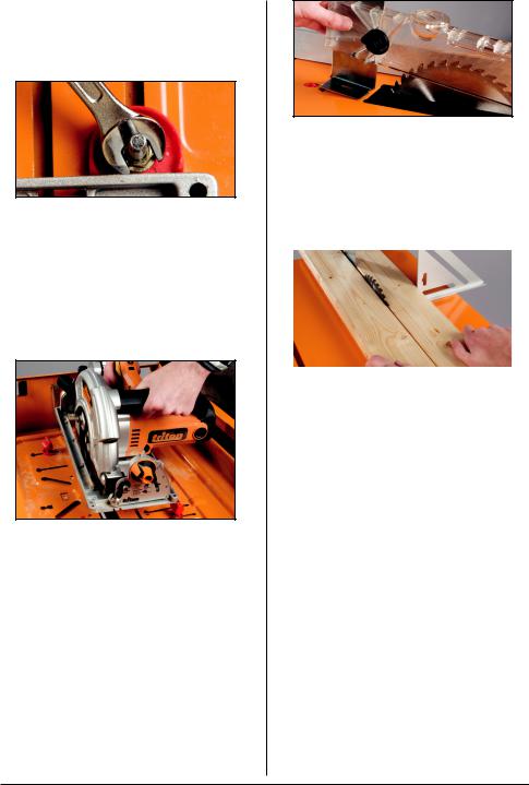
FINAL SAW FITTING
Use your set square to check the blade is exactly 90° to the table. If necessary, adjust the blade angle (see Troubleshooting).
Adjust the position of the saw so that the teeth just touch, front and rear. This step is critical – take your time to get it right!
Fig 7
Spin the blade backwards by hand. The teeth should very lightly skim the fence set at ‘0’. Use a spanner to tighten the flange nuts, temporarily locking the saw in position.
Turn the unit upside down again, taking care not to bump the saw.
Twist or snip the Clam Knobs (M) and Clamp bases
(N) from their moulding tree and trim off any remnants with scissors or a file.
One at a time, replace the temporary saw clamps with the plastic clamp bases. Slide them along the slots until they touch the saw base plate and tighten the flange nuts with a 10mm spanner (Fig 8).
Fig 8
The clamp bases accurately align your saw, so after you’ve fitted them check that you cannot twist or move the saw sideways at all.
Screw the clamp knobs onto the coach bolts (they cut their own threads) until they touch the lip of the saw base plate and clamp it firmly in position (Fig 9).
Fig 9
NOTE:
1.File any burrs in the base plate at the clamp locations to avoid damaging the knobs
2.There is no need to over-tighten knobs. They will still clamp securely, and be vibration-proof, if you leave them about half a turn past where they first scrape on the bas plate
6 Assembly
Insert the remaining short Coach Bolt (L) and a washer into the keyhole slot at the rear of the saw. Fit the Back Stop (O) and slide it along until it touches the base plate. Re-check that the blade is free to spin. Lock the back stop in position with a flange nut (Fig 10).
Fig 10
The clamp knobs have cut-away edges. When all four cut-aways are facing the saw and correctly lined up, you can lift the saw straight out of the clamps, for hand-held use. When re-fitted, the clamp bases will re-align the saw perfectly. Turn the knobs clockwise about half a turn to tighten the saw back down.
When you finish work for the day, either remove your saw from the table, or lower the saw blade using the saw’s height adjuster to allow the saw guard to swing closed as much as possible. This will prevent fatigue in the return spring in the guard.
Fig 11
The saw slot is made from machinable material which can be replaced if significantly damaged. Do not remove this insert under any other circumstances.
FITTING THE OVERHEAD GUARD
Turn the unit right-way up. Unlock the fence and back it away from the blade.
Fit the base of the Overhead Guard Support (G) front first into the slot located behind the saw blade. Pull back the red locking latch, and press the guard support into the table depression. Then push the red latch forward to lock it in position (Fig 12).
Try to wobble the guard support to ensure it is properly locked. The red latch should pop up and be flush with the table top when locked.
Fig 12
CHECKING SAW ALIGNMENT
Loosen the knob on the Overhead Guard (8) about one turn, and remove it for the moment. Check that the overhead guard support is square to the table.
Place two straight pieces of wood on the table and hold them lightly against the blade. The overhead guard support should fit between the pieces when they’re held against the blade, parallel to each other (Fig 13).
|
Fig 13 |
|
|
NOTE: If this is not the case, repeat Saw Fitting |
|
||
procedures or refer to Troubleshooting. |
|
||
Spin the blade by hand before connecting the power |
|
||
to ensure the blade is not touching any part of the saw |
|
||
table. |
|
||
Refit the overhead guard to the support and tighten |
|
||
the knob. Check that the teeth on your blade are |
|
||
pointing in the same direction as the etched symbols |
|
||
on the sides of the guard. If not, you have the blade on |
|
||
the saw backwards. |
|
||
FITTING THE TRIGGER STRAP |
|
||
Check that the saw is not connected to the power, |
|
||
and that the switch on the front panel is in the OFF |
|
||
position. |
|
||
Wrap the trigger strap around the handgrip of the saw, |
|
||
with the furry side facing outwards. Pass the end of |
|
||
the strap through the buckle, until the security |
|
||
loop has passed through. |
|
||
If your saw has a safety button on the side of |
|
||
GB |
|||
the hand-grip, press it and then tighten the strap |
|
||
until the trigger clicks ON. |
|
||
Wrap the free end of the strap around the trigger |
|
||
and it will grip firmly (14). |
|
||
Assembly 7

Fig 14
With most saws, the strap can be slid on and off the saw trigger without having to be undone each time.
CONNECTING THE POWER
Before connecting the power, practice switching on and off. Do not raise the Stop plate.
Press the green switch with your finger to switch the power ON. Tap the stop plate with your hand or thigh to switch OFF (Fig 15).
Fig 15
|
Make sure the switch is OFF, plug the saw into the |
|
switch box inside the front panel and bring power to |
|
the switch box via an extension cable (min 10 Amp). |
|
Before switching on the power, make sure that nothing |
|
is touching the saw blade, or is likely to vibrate into it, |
|
and that your hands are well clear of the blade. |
|
Switch on and off a few times, with the safety guard |
|
raised approx 25mm above the table, and check that |
|
your saw blade is running true. Any buckle or twist in |
|
the blade will be most evident as the blade is slowing |
|
down to stop. If the blade quivers badly on slow-down, |
|
check whether it is properly seated on the saw arbour. |
|
If it is, for best results you may need to replace your |
|
blade. |
|
FITTING THE STORAGE HOOKS |
|
The Storage Hooks (17) enable temporary storage |
|
of table accessories when not in use. Fit them onto |
|
the left or right hand base tube by opening them and |
GB |
clipping them around the tube (Fig 16). |
Fig 16
THE RIP FENCE
The rip fence can be fitted to the left or right hand side of the unit, depending on which you find most comfortable or to suit certain cuts or jigs.
CALIBRATION SETTINGS
The pointer notch is 2.5mm wide, and represents the kerf (width of cut) of most tungsten carbide tipped blades. Provided your blade does remove 2.5mm of material, the scales will be highly accurate with the fence on either side of the blade.
Always sight down directly from above the notch to avoid sighting errors.
LOCKING LEVER TENSION
If locking is too firm or too loose, you can vary the tension of the fence locking levers.
Adjust the Nyloc self-locking nut on the inside of each end panel.
OUTBOARD SUPPORT
By removing the fence from its tracks and replacing it upside down, it can be used to provide effective
outboard support when crosscutting larger workpieces against the protractor.
Secure a batten over the fence arms to create a surface level with the table. The batten should be 14mm thick, or rebated to 14mm thick.
THE PROTRACTOR
With the sandpaper face forward, away from you, guide the protractor strip into the slot at the front panel. Slide the protractor fully along the slot to check that it slides freely.
The Protractor (6) can be used in trailing mode (protractor behind the workpiece, Fig 17), or leading mode (protractor in front of the workpiece, Fig 18). Trailing mode offers 250mm crosscut capacity, leading mode 450mm. Use of trailing mode is recommended unless you require the greater crosscut capacity.
8 Assembly

Fig 17
Fig 18
LOCKING THE PROTRACTOR
You can lock the protractor so that it will not slide in its slot when using the side pressure finger or if attaching a jig.
Slide the protractor partly out of the table slot, loosen the round knob by about 8 turns and rotate the T bolt through 90° so it protrudes through the windows in the strip.
Tighten the knob about 6 turns, then slide the protractor back along the slot to the required position and then tighten the knob so that the protractor is firmly locked in its slot.
Fig 19
CAPTIVE PUSH-STICK & SIDE PRESSURE FINGER Side Pressure Finger
The side pressure finger is on the inside face of the protractor and, when extended, presses the workpiece against the fence on the right hand side of the blade.
The finger can be locked fully retracted or fully extended, and is released by pressing the tabs and sliding sideways (Fig 20).
Prepare the protractor for locking (T bolt across the slot, as per Fig 19) and fully extend the side pressure finger. Place the workpiece in position against the fence and adjust the protractor angle until the finger presses the workpiece against the fence (Fig 20). The finger should flex a little, but avoid applying excessive pressure.
Fig 20
Adjust the position of the protractor in the slot until the finger is about 20mm in front of the blade. Then tighten the protractor knob, locking both the protractor and the angle setting.
Captive Push-Stick
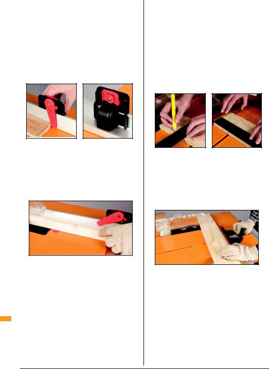
The Captive Push-stick (5) slides along the tracks on the back face of the rip fence. The swing-arm rests against the front face of the fence and should pivot freely (Fig 21). The lock direction of the swing-arm can be reversed, depending on which side of the blade the rip fence is used.
Fig 21
To change the direction, press the rocker switch firmly and the other red stop will appear through the face. Use the stop which allows the swing-arm to pivot towards the blade, not away from it.
Position the push-stick with the swing arm either raised up or resting on top of the workpiece in front of the overhead guard (Fig 22).
Fig 22
As the end of the workpiece passes the captive push-
stick, the swing-arm will drop behind it, allowing you GB to push the work through with your fingers clear of the
blade.
When not in use, hang the protractor and captive pushstick from the storage hooks below the table. The fence can be stored upside down in its clamping tracks.
Assembly 9
THE OVERHEAD GUARD
The overhead guard has hold-down fingers to prevent kick-back. Always ensure the guard is lowered until the fingers flex a little and lightly press the workpiece down on the table.
Having the guard as low as possible will also improve the dust collection by the overhead guard if a vacuum is connected.
The bolt and knob on the overhead guard can be reversed, if necessary, to allow the rip fence to be adjusted closed to the blade when using the fence on the left-hand side of the blade.
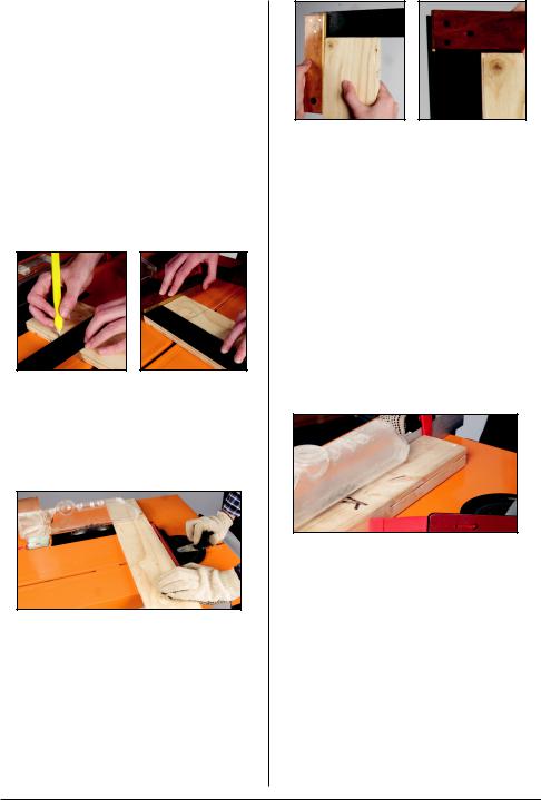
Check your square
First, check your square! Use a board with an absolutely straight edge. Press the handle (base) of the square firmly against it, and use a sharp pencil or utility knife to trace the edge of the blade on the board.
Fig 23
Flip the square over, press it against the straight edge again, and move the blade to the line. Any error in your square is seen as doubled, and is thus more clearly visible.
Crosscutting with the protractor
Set up as shown in (Fig 24), with the safety guard just high enough to admit the piece of wood. Check that the protractor is set at exactly ‘0’.
Fig 24
|
Switch on the power. Hold the wood firmly against the |
|
|
main fence of the protractor and push down lightly with |
|
|
your other hand as you feed the wood smoothly into |
|
|
the blade. |
|
GB |
||
Push the protractor until the workpiece is past the back |
||
|
||
|
of the blade, then switch off the power by bumping the |
|
|
STOP plate with your thigh. |
|
|
If the leading edge of the wood fouled the overhead |
|
|
guard support, or if the back of the blade re-cut or |
|
|
burnished the cut end, your saw is mounted slightly |
|
|
crooked. Adjust the positions of the saw clamp bases |
|
|
and knobs (see ‘Final Saw Fitting’), then check the saw |
|
|
alignment (see ‘Checking Saw Alignment’). |
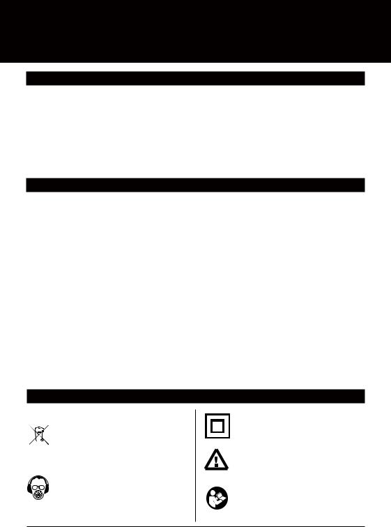
Fig 25
Hold the base of your square against the edge of the timber that was against the protractor face (Fig 25a); adjust the protractor angle slightly if necessary.
Then hold your square against the face which was on the table (Fig 25b). Adjust the angle of the saw blade to the table if necessary, using the saw’s adjuster. See Troubleshooting if unable to get a satisfactory result.
Ripping test
Take a straight piece of wood at least 70mm wide and approx 35mm thick. Place it flat on the table and lower the overhead guard to just above the workpiece.
Lock the rip fence exactly parallel to the blade with a fence setting that will give you an off-cut of, say, 5mm: eg 70mm wide wood, less 3mm for the saw cut, less 5mm for the off-cut = 62mm.
Set up the captive push-stick and side pressure finger. Switch on the power, and feed the wood smoothly. Keep pushing it – ideally without pausing – until it is fully past the blade. Keep fingers well away from the blade. [Fig 26]
Fig 26
Hold the base of the square against the face that was on the saw table and check the cut at various points. Move the fence 1mm closer to the blade, front and rear, and make a finishing cut for best results.
If the leading edge of the wood fouled the overhead guard support, or if the back of the blade re-cut or burnished the cut end, your saw is mounted slightly crooked. Adjust the positions of the saw clamp bases and knobs (see ‘Final Saw Fitting’), then check the saw alignment (see ‘Checking Saw Alignment’).
Basic Ripping
Set the fence parallel to the blade, firmly locked at both ends, with safety guard correctly lowered. Ideally have the wider section of the workpiece between the blade and the fence (Fig 27), so you can keep good control of it with your hands or with the captive push-stick.
10 Assembly
Fig 27
Avoid trapping narrow off-cuts between the blade and the fence, and do not stand directly in line with the blade in case an offcut shoots out towards you.
If the wood binds slightly between the overhead guard support and the fence, you can increase the rear fence setting slightly, say 0.5 to 1mm.
Narrow Ripping
If you want to rip a board into a number of identical narrow strips, or if you want to set the fence closer than 17mm to the blade, the safety guard will prevent access for the fence and the captive push-stick.
Fig 28
To resolve this, make a notched pusher, say 70mm wide, and use it with the side pressure finger (Fig 28). This will enable the guard to be correctly lowered, while creating access for the push-stick.
Ripping Long Pieces
When ripping long pieces which will overhang the rear of the table by more than half their length, either have a friend help you or rig up support using, for example, the Triton Multi-Stand.
Try to keep the workpiece moving, even slowly, during a long rip. Pauses can cause slight steps in the cut. A finishing cut, removing another 1mm, should help if you need a completely smooth edge.
Ripping larger sheets
Lock the rip fence firmly with the same reading at both ends – although you can add 0.5 to 1mm to the rear fence setting for clearance.
Fig 30
Set the overhead guard as low as possible. Push the workpiece against the fence and feed gently into the blade, keeping one hand on either side of the work (Fig 30). Switch off with your thigh when you finish the cut.
For ripping up to 450mm off very large sheets, use one or two Triton Multi-Stands with a suitable length of wood clamped in the head(s) to support the offcut (Fig 31).
Fig 31
For ripping widths greater than 450mm, use the saw hand-held. Remove the power saw from the table, remove the trigger strap, and check the operation of the saw guard. Clamp a guide to the workpiece, which should be securely supported off the floor on battens or packers. Never do a freehand cut following a pencil line; it’s dangerous.
Double ripping
You can double the maximum depth of cut by turning the wood over, end for end, and making a second cut. If the blade is exactly square to the table, and if both edges of the wood are dressed square, the two cuts should line up (Fig 32).
Fig 32
The overhead guard assembly cannot be fitted for the first cut, but must be fitted for the second. Ensure your fingers remain well clear of the blade, even if the wood ‘kicks’ or your hands slip. Use the captive push-stick and side pressure finger. Make both cuts of similar depth: for example, cut a 90mm wide piece in 2 cuts of approx 46mm each.
Saw Fitting |
|
GB |
•If a slot you plan to use for your Saw Clamps (13 & 14) tends to foul an obstruction on the lip of the baseplate, or the saw motor, or the adjuster controlling the blade height: use a different slot for the clamp
•If your saw has a very short baseplate: use the four inner slots. NOTE: The advised 10mm gap between the blade and the end of the slot in the table insert is a guide only. You may move the saw a little closer to the
Assembly 11

front panel for better clamp locations
•If your blade will not fit through the slot because you have a riving knife fitted to the saw: extend the slot towards the front of the insert by using a hacksaw blade or a file on edge
•If one of the clamps fouls the saw motor: replace it with one of the Temporary Saw Clamps (18) on a shortened coach bolt
Saw blade cannot be adjusted fully square to the table
•First, check that the saw does not have a limit screw in the baseplate, underneath the angle quadrant, that is preventing you from reaching 0°. Check that nothing else is fouling the saw motor or top guard, and thus preventing full tilt
•Check that the mountings between the saw baseplate and the motor housing are reasonably firm. Tighten them, if possible, or upgrade your saw
•If you cannot find any other solution, remove your saw and insert a full length strip of thin packing between the narrow part of the baseplate and the table, to slightly tilt the saw. Ideally tape or glue the strip to the table, then re-tighten the clamp knobs
Very thin saw blades (teeth approx. 1.5mm thick)
Thin slitting blades can be fitted, though we recommend standard blades approx 2.5mm thick, because:
•Thin blades are very flexible and are easily bent or twisted when fitting the saw, making them difficult to align
•With a thin blade the scales will only be accurate when the fence is set on the right hand side of the blade. You will have to make an allowance when setting the fence to the left
•A thicker blade will not cause the above problems, and should also give you smoother cuts, less flexing in dense wood, and better results when planing
NOTE: 1.5mm thin blades cut 2.0 to 2.2mm wide. If fitting a thin blade saw, insert a strip of 0.5mm cardboard between the blade and the fence, as a
temporary spacer, and hold the blade against it whilst aligning the saw. You will not be able to spin the blade by hand.
Protractor scale is slightly inaccurate
•The scale pointer can be adjusted by using a small
GB |
screwdriver to lever out the lens, and then prising the |
|
pointer sideways |
||
|
•First, make test cuts and adjust the protractor angle setting until you are cutting exactly square. Then insert the screwdriver blade into the appropriate slot beside the pointer, and twist until the tip of the pointer is exactly opposite 0°
Workpiece binds on overhead guard support when ripping
•First, check that the fence was set at identical readings front and rear. If it was, try increasing the rear fence setting slightly (0.5mm – 1mm) and repeat the cut
•Check that the saw blade is correctly lined up with the overhead guide support
•Check that the overhead guard support is square to the table. To square it up: use a straight piece of material, such as a block of wood, to spread the load as you carefully bend it square
•If the problem persists: try re-aligning the saw slightly so that the overhead guard support fits into the kerf of the blade without jamming
High spots, burn marks and re-cut damage on the workpiece
If the back of the blade re-cuts or burnishes the workpiece when you cross-cut against the protractor, or when you rip against the parallel fence, the most likely reason is that your saw is mounted slightly skew. Before realigning your saw, check a few other possible causes:
•Remove the blade from the saw, check that the arbour and washers are clean and that the blade is well seated. If an arbour-reducing washer is fitted, make sure it is a snug fit and not proud of the blade disc.
•Check for blade flatness with a metal straight edge at various points across the centre hole. If significantly buckled, replace the blade
•Check for arbour float in your saw bearings by disconnecting the power, gripping the blade nut and pulling in and out in the direction of the
shaft. Any movement is undesirable. If you want perfectly square cuts, you may have to repair or replace your saw
12 Assembly

WARRANTY
To register your guarantee visit our web site at www.tritontools.com* and enter your details.
Your details will be included on our mailing list (unless indicated otherwise) for information on future releases. Details provided will not
be made available to any third party.
PURCHASE RECORD
Date of Purchase: |
___ / ___ / ____ |
Model: TCB100 |
|
Serial Number: __________________
(Located on motor label)
Retain your receipt as proof of purchase
Triton Precision Power Tools guarantees to the purchaser of this product that if any part proves to be defective due to faulty materials or workmanship within 12 MONTHS from the date of original purchase, Triton will repair, or at its discretion replace, the faulty part free of charge.
This guarantee does not apply to commercial use nor does it extend to normal wear and tear or damage as a result of accident, abuse or misuse.
* Register online within 30 days. Terms & conditions apply.
This does not affect your statutory rights
GB
Warenty 13
Dit product heeft een aantal unieke kenmerken. Lees deze handleiding a.u.b., zelfs als u bekend bent met deze Workcentre, zodat u optimaal profiteert van het unieke ontwerp.
Houd deze handleiding bij de hand en zorg ervoor dat alle gebruikers van dit gereedschap de instructies hebben gelezen en volledig hebben begrepen.
INHOUD
Specificaties |
14 |
Symbolen |
14 |
Onderdelen |
15 |
Veiligheidsvoorschriften |
16 |
Montage |
17 |
Garantie |
26 |
SPECIFICATIES
Onderdeelnr: |
TCB100 |
Geschikt voor: |
De meeste cirkelzagen (185mm - 235mm) |
Bewerkingen: |
Schulpen, afschuinen, afkorten |
Schulpcapaciteit: |
0 - 450mm |
Doorsnedecapaciteit: |
tot 450 mm breed |
Afmetingen uitgeklapt: |
ca 980mm x 380mm x 1040mm |
Afmetingen ingeklapt: |
ca 900mm x 540mm x 300mm |
Standaardkenmerken: |
Parallelgeleider met een capaciteit van 0 tot 450 mm, |
|
doorzichtige beschermkap, aandrukvingers tegen terugslag & |
|
stofafzuigaansluiting, ingebouwde stuurdwinger & drukvinger |
Optionele accessoires: |
Verstekgeleider, stofopvangbak & stofzak |
Bescherm uw gehoor |
|
Draag altijd geschikte gehoorbescherming bij gereedschap dat een geluidsniveau van meer dan 85dB produceert.
SYMBOLEN
|
BESCHERMING VAN HET MILIEU |
||
|
|
|
Elektrische producten mogen niet worden |
|
|
|
afgevoerd met het normale huisvuil. Indien de |
|
|
|
mogelijkheid bestaat, dient u het product te |
|
|
|
recyclen. Vraag de plaatselijke autoriteiten of |
|
|
|
|
|
|
|
winkelier om advies betreffende recyclen. |
NL |
|||
|
|
|
Draag altijd oor-, oogen |
|
|
|
luchtwegenbescherming. |
Dubbel geïsoleerd.
Instructie waarschuwing.
Gebruik niet alvorens en begrijpend de volledige werkende instructies te bekijken
14 Inhoud / Specificaties / Symbolen

ONDERDELEN
A. Tafelblad (1) |
B. |
Achterste poten (2) |
|
C. |
Voorste poten (2) |
|
D. |
Parallelgeleider (1) |
E. Stuurdwinger (1) |
F. Verstekgeleider (1) |
G+H. Steun beschermkap (1) |
BEVESTIGINGSONDERDELEN
I. M6 x 40 mm |
O. Achteraanslag voor zaag (1) |
|
slotschroeven (4) |
||
|
||
J. Borgringen (5) |
|
|
K. M6 flensmoeren (5) |
P. Omsnoeringsband trekker (1) |
|
|
||
L. M6 x 12 mm |
Q. Opberghaken (2) |
|
slotschroeven (1) |
|
|
M. Klemknop (4) |
|
|
|
R. Tijdelijke zaagklemmen (4) |
|
N. Klemvoet (4) |
|
NL
Onderdelen 15

VEILIGHEIDSVOORSCHRIFTEN
WAARSCHUWING Lees alle bedieningen
veiligheidsvoorschriften. Het niet opvolgen van alle voorschriften die hieronder vermeld staan,
kan resulteren in een elektrische schok, brand en/of ernstig letsel.
Bewaar deze voorschriften voor toekomstig gebruik. De term “elektrisch gereedschap” in alle hieronder vermelde waarschuwingen heeft betrekking op uw elektrische gereedschap dat op de stroom is aangesloten (met een snoer) of met een accu wordt gevoed (snoerloos).
1) Veiligheid in de werkruimte
a) Houd de werkruimte schoon en zorg voor een goede verlichting. Rommelige en donkere ruimtes leiden vaak tot ongelukken.
b) Werk niet met elektrisch gereedschap in explosieve omgevingen, bijvoorbeeld in de aanwezigheid van ontvlambare vloeistoffen, gassen of stof. Elektrisch gereedschap brengt vonken teweeg die stof of dampen kunnen doen ontbranden.
c) Houd kinderen en omstanders uit de buurt wanneer u elektrisch gereedschap bedient. Door afleiding kunt u de controle over het gereedschap verliezen.
2) Elektrische veiligheid
a) De stekkers van het elektrische gereedschap moeten passen bij het stopcontact. Pas de stekker niet aan. Gebruik geen adapterstekkers bij geaard elektrisch gereedschap. Het gebruik van ongewijzigde stekkers en passende stopcontacten vermindert het risico op een elektrische schok.
b) Vermijd lichamelijk contact met geaarde oppervlakken zoals pijpen, radiatoren, fornuizen en koelkasten. Het risico op een elektrische schok neemt toe als uw lichaam geaard wordt.
c) Laat elektrisch gereedschap niet nat worden.
Wanneer elektrisch gereedschap nat wordt, neemt het risico op een elektrische schok toe.
d) Beschadig het snoer niet. Gebruik het snoer nooit om het elektrisch gereedschap te dragen, te trekken of om de stekker uit het stopcontact te trekken. Houd het snoer uit de buurt van hitte, olie, scherpe randen of bewegende delen. Een beschadigd of in de knoop geraakt snoeren verhoogt het risico op een elektrische schok toe.
|
e) Wanneer u elektrisch gereedschap buiten |
|
NL |
||
gebruikt, maak dan gebruik van een verlengsnoer |
||
|
||
|
dat geschikt is voor gebruik buitenshuis. Gebruik |
|
|
een verlengsnoer dat geschikt is voor gebruik |
|
|
buitenshuis om het risico op een elektrische schok te |
|
|
verminderen. |
|
|
f) Indien het onvermijdelijk is elektrisch gereedschap |
|
|
te gebruiken in een vochtige omgeving, gebruik |
dan een energiebron met een aardlek beveiliging (Residual Currency Device). Het gebruik van een RCD vermindert het risico op een elektrische schok.
3) Persoonlijke veiligheid
a)Blijf alert en gebruik uw gezonde verstand wanneer u elektrisch gereedschap bedient. Gebruik het elektrisch gereedschap niet wanneer u vermoeid bent of onder invloed van drugs, alcohol of medicijnen. Onoplettendheid tijdens het bedienen van elektrisch gereedschap kan leiden tot ernstig letsel.
b)Maak gebruik van persoonlijke bescherming. Draag altijd een veiligheidsbril. Passende bescherming voor de omstandigheden, zoals een stofmasker, niet-slippende veiligheidsschoenen een helm of gehoorbescherming, vermindert het risico op persoonlijk letsel.
c)Zorg ervoor dat het apparaat niet per ongeluk wordt gestart. Controleer of de schakelaar in de ‘uit’ stand staat voordat u de stekker in het stopcontact steekt. Het dragen van elektrisch gereedschap met uw vinger op de schakelaar of het aansluiten op de stroom van elektrisch gereedschap met de schakelaar ingeschakeld kan tot ongelukken leiden.
d)Verwijder alle stelof moersleutels voordat u het elektrische gereedschap inschakelt. Een moerof stelsleutel die zich op een draaiend onderdeel van het elektrische gereedschap bevindt, kan leiden tot letsel.
e)Reik niet te ver. Blijf altijd stevig en in balans staan. Zo houdt u meer controle over het elektrische gereedschap in onverwachte situaties.
f)Draag geschikte kleding. Draag geen loshangende kleding of sieraden. Houd haren, kleding en handschoenen uit de buurt van bewegende delen.
Loshangende kleding, sieraden en los hangende haren kunnen vast komen te zitten in bewegende delen.
g)Als er onderdelen voor stofafvoeren stofverzameling worden meegeleverd, sluit deze dan aan en gebruik deze op de juiste wijze.
Het gebruik van deze onderdelen kan het risico op stofgerelateerde ongelukken verminderen.
4) Gebruik en verzorging van elektrisch gereedschap
a)Forceer elektrisch gereedschap niet. Gebruik elektrisch gereedschap dat geschikt is voor het werk dat u wilt uitvoeren. Geschikt elektrisch gereedschap werkt beter en veiliger op een passende snelheid.
b)Gebruik het elektrische gereedschap niet als de schakelaar het apparaat niet inen uitschakelt.
Elektrisch gereedschap dat niet bediend kan worden met de schakelaar is gevaarlijk en moet gerepareerd worden.
16 Veiligheidsvoorschriften

c) Haal de stekker uit het stopcontact voordat u |
f) Houd snijwerktuigen scherp en schoon. Goed |
|
instellingen aanpast, toebehoren verwisselt of |
onderhouden snijwerktuigen met scherpe messen |
|
het elektrische gereedschap opbergt. Dergelijke |
slaan minder snel vast en zijn gemakkelijker te |
|
voorzorgsmaatregelen verminderen het risico op het |
bedienen. |
|
per ongeluk starten van het elektrische gereedschap. |
g) Gebruik het elektrische gereedschap, toebehoren |
|
|
||
d) Berg elektrisch gereedschap dat niet in gebruik is |
en onderdelen, etc. volgens deze instructies en |
|
op buiten bereik van kinderen en laat mensen die |
volgens bestemming voor het specifieke type |
|
niet bekend zijn met het elektrische gereedschap |
elektrisch gereedschap, en houd daarbij rekening |
|
of met deze instructies het elektrische |
met de werkomstandigheden en het uit te voeren |
|
gereedschap niet bedienen. Elektrisch gereedschap |
werk. Gebruik van elektrisch gereedschap voor |
|
is gevaarlijk in de handen van onervaren gebruikers. |
werkzaamheden die verschillen van die waarvoor |
|
e) Onderhoud uw elektrisch gereedschap. Controleer |
het apparaat bestemd is, kan leiden tot gevaarlijke |
|
situaties. |
||
op foutieve uitlijning of het vastslaan van |
||
|
||
bewegende delen, gebroken onderdelen en |
5) Onderhoud |
|
elke andere afwijking die de werking van het |
a) Laat uw elektrische gereedschap onderhouden |
|
elektrische gereedschap zou kunnen beïnvloeden. |
||
door een gekwalificeerde vakman en gebruik |
||
Indien het elektrische gereedschap beschadigd |
||
alleen identieke vervangstukken. Zo bent u er zeker |
||
is, moet u het laten repareren voordat u het weer |
||
van dat de veiligheid van het elektrische gereedschap |
||
gebruikt. Veel ongelukken worden veroorzaakt door |
||
gewaarborgd blijft. |
||
slecht onderhouden elektrisch gereedschap. |
||
|
MONTAGE |
|
|
|
|
|
||
UITPAKKEN |
(kerf) van 2,5 mm heeft. Gebruik de zijde van |
|
|||||
• Pak uw tafel voorzichtig uit en controleer of alle |
de inkeping overeenkomstig de zijde waar u de |
|
|||||
geleider gemonteerd heeft voor uitlijning met de |
|
||||||
onderdelen aanwezig zijn en in goede staat verkeren |
|
||||||
schaalverdeling op de geleiderarmen. |
|
||||||
• Gebruik dit gereedschap niet indien er onderdelen |
|
||||||
OPMERKING: Als uw zaag een zeer dun zaagblad |
|
||||||
ontbreken of beschadigd zijn. Breng het in dat geval |
|
||||||
heeft, lees dan ‘Dunne zaagbladen gebruiken’ in |
|
||||||
terug naar uw winkelier |
|
||||||
‘Probleemoplossing’. |
|
||||||
|
|
|
|
||||
MONTAGE VAN DE PARALLELGELEIDER |
|
|
|
|
|
||
|
|
|
|
|
|||
Zet de spangrepen voor de geleiderklemmen aan het |
|
|
|
|
|
||
einde van de panelen volledig los. Vouw de armen |
|
|
|
|
|
||
van de parallelgeleider (D) open en schuif ze in de |
|
|
|
|
|
||
geleidingsgroeven aan de rechterzijde van de tafel |
|
|
|
|
|
||
(gezien vanaf het voorpaneel met de schakelaar). Zorg |
|
|
|
|
|
||
dat het hogere gedeelte van de geleider in de richting |
|
|
|
|
|
||
van het plastic inzetstuk in het tafelblad wijst (Fig 1). |
|
|
|
|
|
||
|
|
|
Plaats de geleider aan de rechterzijde en lijn de zijde |
|
|||
|
|
|
|
||||
|
|
|
van de inkeping die zich het dichtst bij de geleider |
|
|||
|
|
|
|
Fig 2 |
|
||
|
|
|
bevindt uit met ‘0’ op de schaalverdeling (Fig 2). |
|
|||
|
|
|
Druk de zwarte plastic spangrepen op het vooren |
|
|||
|
|
|
achterpaneel naar omlaag om de geleider in deze |
|
|||
|
|
|
stand vast te zetten. |
|
|||
|
|
|
Gebruik een nauwkeurige winkelhaak om te |
|
|||
|
Fig 1 |
|
controleren of de korte zijde van de geleider aan |
|
|||
|
|
beide zijden loodrecht op de tafel staat. U kunt de |
|
||||
|
|
|
|
||||
Bestudeer de schaalverdelingwijzers van de geleider |
geleider indien nodig kantelen met behulp van de |
|
|||||
(J). De parallelgeleider kan zowel aan de rechterals |
krikschroeven (Fig 3). |
NL |
|||||
|
|||||||
aan de linkerzijde van het zaagblad gemonteerd |
Als u aanzienlijke aanpassingen aanbrengt, is het |
|
|||||
worden, afhankelijk van de zaagsnede die u wenst te |
|
||||||
nodig de geleider van de tafel af te schuiven en de |
|
||||||
maken of van uw persoonlijke voorkeur. |
|
||||||
scharnierschroeven waarmee de geleiderarmen zijn |
|
||||||
Dankzij de inkeping van 2,5 mm is de schaalverdeling |
|
||||||
vastgemaakt vaster of losser te draaien. De armen |
|
||||||
nauwkeurig aan beide zijden van het zaagblad, |
dienen stijf doch vrij the scharnieren, zonder speling. |
|
|||||
indien uw zaag een standaard zaagbreedte |
|
|
|
|
|
||
Veiligheidsvoorschriften / Montage 17
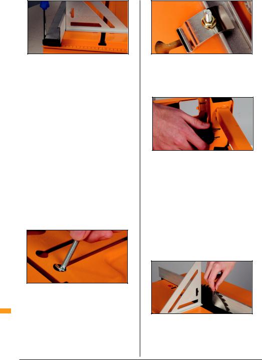
Fig 3
Draai het tafelblad (A) ondersteboven en plaats het op een tafel of bank en laat de geleider voorbij de rand hangen. U kunt de tafel eventueel ook op houten
blokken plaatsen zolang deze hoog genoeg zijn om het zaagblad, bij maximale zaagdiepte, door de gleuf in de tafel te schuiven.
Zorg dat de zaag niet op netstroom is aangesloten en vergrendel het zaagblad op de maximale zaagdiepte. Controleer of het zaagblad op 0° is ingesteld op hoekaanpassing van de zaag.
Trek de beschermkap van de zaag naar achteren en laat de zaag met de voorzijde in de richting van de schakelaar in de gleuf zakken.
OPMERKING: De gleuf is voorzien voor zaagbladen van 235 mm. Als uw zaag kleiner is, schuif ze dan naar achteren tot de achterzijde van het zaagblad zich op ongeveer 10 mm van de achterzijde van de gleuf bevindt. Als uw zaagblad niet in de gleuf past, raadpleeg dan ‘Probleemoplossing – Zaagmontage’.
Kies de vier sleutelgatkerven die de beste positie voor het vastklemmen van uw zaag bieden. Als u verschillende opties heeft, kies dan de kerven die het verst uit elkaar liggen gezien over de volledige lengte van de grondplaat. Probeer belemmeringen op de zaag, zoals verhoogde segmenten op de voetplaat of de hendel voor hoogteaanpassing van de zaag, te vermijden.
Fig 4
Verwijder de zaag en plaats de vier lange slotschroeven (I), met de borgringen (J) onder de koppen zoals afgebeeld in (Fig 4), in de gekozen kerven.
Plaats de zaag terug, met het blad tegen de geleider. NL Draai de tijdelijke zaagklemmen (R) met de hand
stevig vast op de stopschroeven met behulp van de flensmoeren (K). Zie Fig 5 hieronder.
Fig 5
MONTAGE VAN DE POTEN
Schuif de achterste poten (B) volledig in hun behuizing aan de achterzijde van de tafel. Schuif de onbedekte uiteinden van de voorste poten (C) in de openingen van het voorpaneel. Zet ze vast door de knoppen vast te draaien (Fig 6).
Fig 6
OPMERKING: U kunt wat gekraak horen wanneer de poedercoating breekt – dit is normaal.
Keer de zaagtafel om en controleer of de vier poten vast op de grond staan. Regel dit zonodig af door een van de poten een beetje uit zijn behuizing te trekken tot de tafel stabiel staat.
UITEINDELIJKE ZAAGMONTAGE
Gebruik uw winkelhaak om te controleren of het zaagblad met een hoek van exact 90° tegenover het tafelblad staat. Stel de hoek van het zaagblad indien nodig bij (zie Probleemoplossing).
Regel de positie van de zaag zodanig dat de tanden aan de voor en achterzijde de geleider lichtjes raken. Dit is een cruciale stap – neem de tijd om ze juist uit te voeren!
Fig 7
Draai het blad met de hand naar achteren. De tanden dienen de geleider, ingesteld op ‘0’, heel lichtjes te raken. Draai de flensmoeren met een moersleutel vast zodat de zaag tijdelijk in deze positie vergrendeld wordt.
18 Montage

Draai de tafel weer ondersteboven maar zorg ervoor dat zaag nergens tegen stoot.
Draai of knip de klemknoppen (M) en de klemvoeten
(N) los van het plastic frame en verwijder restanten met een schaar of een vijl.
Vervang de tijdelijke zaagklemmen één voor één door de plastic klemvoeten. Schuif ze langs de kerven tot ze de grondplaat raken en span de flensmoeren met een moersleutel van 10 mm aan (Fig 8).
Fig 8
De klemvoeten lijnen uw zaag nauwkeurig uit, dus controleer dat de zaag niet kunt draaien of zijwaarts bewegen nadat u ze gemonteerd heeft.
Schroef de klemknoppen op de stopschroeven (deze zijn zelftappend) tot ze de lip van de grondplaat raken en de plaat stevig in deze positie vastzetten (Fig 9).
Fig 9
OPMERKING:
1.Vijl bramen van de grondplaat ter hoogte van de klemmen af om beschadiging van de knoppen te vermijden
2.Het is niet nodig de knoppen overmatig aan te spannen. Ze klemmen stevig aan en zijn bestand tegen trillingen als u ze nog ongeveer een halve slag aandraait nadat ze de grondplaat raken
Plaats de laatste korte stopschroef (L) met een borgring in de sleutelgatkerf aan de achterzijde van de zaag. Monteer de achteraanslag (O) en verschuif hem tot hij de grondplaat raakt. Controleer nogmaals of het zaagblad vrij ronddraait. Vergrendel de achteraanslag in deze positie met een flensmoer (Fig 10).
Fig 10
De klemknoppen hebben een ronde en een rechte zijde. Wanneer alle vier rechte zijdes in de richting van de zaag wijzen en correct uitgelijnd zijn, kan de zaag vlot uit de klemmen gehaald worden zodat u ze als handgereedschap kunt gebruiken. Wanneer u de zaag terugplaatst, zullen de klemvoeten de zaag opnieuw perfect uitlijnen. Draai de knoppen ongeveer een halve slag naar rechts om de zaag opnieuw vast te klemmen.
Haal op het einde van de werkdag ofwel uw zaag uit de tafel, of laat het zaagblad met behulp van de hendel voor hoogteaanpassing van de zaag zakken zodat
de beschermkap van de zaag zo ver als mogelijk kan dichtklappen. Zo vermijd u metaalmoeheid van de trekveer in de beschermkap.
De zaaggleuf is vervaardigd uit verspaanbaar materiaal dat in geval van aanzienlijke schade vervangen kan worden. Verwijder dit inzetstuk nooit.
Fig 11
MONTAGE VAN DE BESCHERMKAP
Zet de tafel rechtop. Ontgrendel de geleider en schuif hem weg van het zaagblad.
Plaats de voorzijde van de steun voor de beschermkap
(G) in de gleuf achter het zaagblad. Trek de rode grendel naar achteren en druk de beschermkapsteun in het verzonken gedeelte van de tafel. Druk daarna de rode grendel naar voren om hem in deze positie vast te zetten (Fig 12).
Probeer de beschermkap heen en weer te bewegen om te zorgen dat hij goed vastzit. De grendel komt naar boven en komt gelijk met de tafel te zitten wanneer hij is vergrendeld.
Fig 12
NL
CONTROLE VAN DE ZAAGUITLIJNING
Draai de knop op de beschermkap (8) ongeveer een halve slag los, en verwijder hem tijdelijk. Controleer of de steun van de beschermkap loodrecht op de tafel
Montage 19

staat. Raadpleeg Probleemoplossing – 5 indien dit niet het geval is.
Plaats twee rechte stukken hout op de tafel en houd ze lichtjes tegen het zaagblad. De steun van de beschermkap dient tussen de stukken te passen
wanneer u ze evenwijdig van elkaar tegen het zaagblad houdt (Fig 13).
Fig 13
OPMERKING: Als dit niet het geval is, herhaal dan de procedures voor de montage van de zaag of raadpleeg Probleemoplossing.
Draai het zaagblad met de hand rond voordat u de stroom aansluit om zeker te zijn dat het zaagblad geen enkel onderdeel van de zaagtafel raakt.
Plaats de beschermkap terug op de steun en draai de knop vast. Controleer of de tanden van uw zaagblad in de richting wijzen die wordt aangegeven op de gegraveerde symbolen aan de zijkanten van de beschermkap. Als dit niet het geval is, zit het zaagblad achterstevoren op uw zaag.
DE OMSNOERINGSBAND VOOR DE TREKKER PLAATSEN
Zorg dat de zaag niet op netstroom is aangesloten en dat de schakelaar op het voorpaneel zich in de ‘uit’ stand bevindt.
Wikkel de omsnoeringsband rond de handgreep van de zaag, met het bont naar buiten. Haal het uiteinde van de band door de gesp tot voorbij de veiligheidslus.
Als uw zaag een veiligheidsknop heeft aan de zijkant van de handgreep, druk deze dan in en haal daarna de band aan tot de trekker ‘aan’ klikt.
Wikkel het losse uiteinde van de band rond de trekker, het uiteinde zal zich stevig vastzetten (14).
NL
Fig 14
Bij de meeste zagen kan de band van de trekker af en terug op de trekker geschoven worden zonder dat u hem steeds moet losmaken.
OP NETSTROOM AANSLUITEN
Oefen u in het inen uitschakelen voor u de netstroom aansluit. Hef de stopplaat niet op.
Druk op de witte schakelaar om de zaagtafel aan te zetten. Tik tegen de stopplaat met uw hand of dij om ze uit te schakelen (Fig 15).
Fig 15
Zorg dat de schakelaar in de ‘uit’ stand staat, stop de stekker van de zaag in het stopcontact aan de
achterzijde van de schakelaar binnenin het voorpaneel en gebruik een verlengsnoer (min 10 Amp) om de schakelaar van stroom te voorzien.
Zorg ervoor dat niets het zaagblad raakt, of door trillingen ernaartoe kan bewegen en dat uw handen zich niet in de buurt van het zaagblad bevinden voor u de zaagtafel inschakelt.
Schakel de tafel een paar keer in en uit, met de beschermkap ongeveer 25 mm boven de tafel en controleer of uw zaagblad zuiver loopt. Een knik of slag in het zaagblad zal duidelijk te zien zijn wanneer het blad vertraagt voor het stopt Als het blad zwaar trilt wanneer het vertraagt, controleer dan of het correct op de spil van de zaag gemonteerd is. Als het correct gemonteerd is, kan het nodig zijn het zaagblad te vervangen om de beste prestaties uit de tafel te halen.
DE OPBERGHAKEN PLAATSEN
U kunt de opberghaken (Q) gebruiken om toebehoren van de tafel die u tijdelijk niet gebruikt op te bergen. Plaats ze op de linker of rechter buis aan de onderzijde van de tafel door ze te openen en rond de buis te clippen (Fig 16).
Fig 16
DE PARALLELGELEIDER
De parallelgeleider kan aan de linkerof rechterzijde van de tafel geplaatst worden, afhankelijk van wat het comfortabelst is voor u of voor bepaalde soorten zaagsneden of mallen.
20 Montage
SCHAALVERDELING
De inkeping is 2,5 mm breed, en is gelijk aan de kerf (breedte van de zaagsnede) van de meeste tungsten carbide zaagbladen. Indien uw zaagblad inderdaad 2,5 mm materiaal verwijdert, is de schaalverdeling zeer nauwkeurig met de geleider aan eender welke zijde van het zaagblad.
Controleer uw instellingen altijd rechtstreeks van boven de inkeping om zichtfouten te vermijden.
DRUK VAN DE SPANGREEP
Als de vergrendeling te vast of te licht is, kunt u de druk die wordt uitgeoefend door de spangrepen van de geleider aanpassen.
Regel de zelfborgende moer aan de binnenkant van ieder eindpaneel af.
BIJKOMENDE ONDERSTEUNING
Als u de geleider uit de rails haalt en hem ondersteboven terugplaatst, kunt u hem als doeltreffende bijkomende ondersteuning gebruiken wanneer u grotere werkstukken met behulp van de verstekgeleider afkort.
Bevestig een panlat over de geleiderarmen zodat het oppervlak gelijk is met de tafel. Gebruik een panlat van ongeveer 14 mm dik, of met een sponning tot op 14 mm dikte.
DE VERSTEKGELEIDER
Schuif de geleider met het zandpapier naar voren, weg van u, in de gleuf bij het voorpaneel. Schuif de verstekgeleider de volledige lengte van de gleuf om te controleren dat hij vlot schuift.
De verstekgeleider (6) kan in de navolgende modus (met de verstekgeleider achter het werkstuk, Fig 17), of voorafgaande modus (met de verstekgeleider voor het werkstuk, Fig 18). In de navolgende modus beschikt
u over 250 mm afkortcapaciteit, in de voorafgaande modus over 450 mm. Er wordt aangeraden de navolgende modus te gebruiken tenzij u een grotere afkortcapaciteit nodig heeft.
Fig 17
Fig 18
DE VERSTEKGELEIDER VERGRENDELEN
U kunt de verstekgeleider vergrendelen zodat hij niet langs de gleuf kan schuiven wanneer u de drukvinger aan de zijkant gebruikt of een mal bevestigt.
Schuif de verstekgeleider gedeeltelijk uit de gleuf in de tafel, draai de ronde knop ongeveer 8 slagen los en draai de T-bout 90° zodat hij door de gaten in de strip steekt.
Draai de knop ongeveer 6 slagen vast, schuif de verstekgeleider terug in de gleuf tot op de gewenste positie en draai de knop volledig vast zodat de verstekgeleider stevig in de gleuf wordt vastgezet.
Fig 19
STUURDWINGER & DRUKVINGER Drukvinger
De drukvinger bevindt zich aan de binnenzijde van de verstekgeleider en drukt, wanneer hij uitgeschoven is, het werkstuk tegen de geleider aan de rechterzijde van het zaagblad.
De geleider kan volledig uitgeschoven of volledig ingeschoven worden vergrendeld, en wordt vrijgegeven door op de uitstulpingen te drukken en hem zijwaarts te schuiven (Fig 20).
Maak de verstekgeleider klaar voor vergrendeling (T- bout over de gleuf, zie Fig 19) en schuif de drukvinger volledig uit. Plaats het werkstuk tegen de geleider
en regel de hoek van de verstekgeleider af tot de drukvinger het werkstuk tegen de geleider drukt (Fig 20). De drukvinger dient een beetje door te buigen, maar geen overmatige druk uit te oefenen.
NL
Fig 20
Montage 21
Stel de positie van de verstekgeleider bij tot de drukvinger zich ongeveer 20 mm voor het zaagblad bevindt. Schroef nu de knop van de verstekgeleider vast, zodat de verstekgeleider en de hoekinstelling worden vergrendeld.
Stuurdwinger
De stuurdwinger (5) glijdt langs de groeven aan de achterzijde van de parallelgeleider. De zwaaiarm rust tegen de voorzijde van de geleider en dient vrij te draaien (Fig 21). De vergrendelrichting van de zwaaiarm kan omgekeerd worden, afhankelijk van
waar de parallelgeleider zich bevindt ten opzichte van het zaagblad.
Fig 21
Om de richting te veranderen drukt u de tuimelschakelaar stevig in zodat de andere rode buffer aan voorzijde van de zwaaiarm te voorschijn komt. Gebruik de buffer die zorgt dat de zwaaiarm in de richting van het zaagblad draait, en dus niet weg van het blad.
Plaats de stuurdwinger voor de beschermkap met de zwaaiarm rechtop of laat hem rusten op de bovenzijde van het werkstuk (Fig 22).
Fig 22
Wanneer het werkstuk langs de stuurdwinger voorbij gaat, valt de zwaaiarm erachter, zodat u het werkstuk verder kunt schuiven zonder met uw vingers in de buurt van het zaagblad te komen.
Hang de verstekgeleider en de stuurdwinger aan de opberghaken onder de tafel wanneer u ze niet gebruikt. U kunt de geleider ondersteboven in de klemgroeven opbergen.
NL
BESCHERMKAP
De beschermkap heeft aandrukvingers om terugslag te voorkomen. Laat de kap zodanig zakken dat de vingers een beetje doorbuigen en het werkstuk lichtjes tegen de tafel aan drukken.
Indien u een stofzuiger aansluit zal de stofafzuiging ook efficiënter zijn wanneer u de kap zo laag mogelijk vastzet.
De bout en knop van de beschermkap kunnen indien nodig omgekeerd worden, zodat de parallelgeleider dichter bij het zaagblad kan wanneer u de parallelgeleider aan de linkerzijde van het zaagblad plaatst.
Controleer uw winkelhaak
Controleer eerst uw winkelhaak! Gebruik een plank met een volledig rechte rand. Druk het handvat (voet) van de winkelhaak stevig tegen de rand en gebruik een scherp potlood of een hobbymes om de rand van het blad op de plank af te tekenen.
Fig 23
Draai de winkelhaak om, druk hem opnieuw tegen de rechte rand en verplaats het blad tot tegen de lijn. Fouten in uw winkelhaak worden hierdoor verdubbeld en zijn dus beter zichtbaar
Afkorten met de verstekgeleider
Gebruik de opstelling die is afgebeeld in Fig 24, met de beschermkap net hoog genoeg zodat het stuk hout er onderdoor kan. Controleer of de verstekgeleider precies op ‘0’ is afgesteld.
Fig 24
Schakel de zaagtafel in. Druk het hout stevig tegen de hoofdgeleider van de verstekgeleider en oefen wat neerwaartse druk uit met uw vrije hand terwijl u het hout met een gelijkmatige beweging langs de zaag passeert.
Schuif de verstekgeleider naar voren tot het werkstuk voorbij het zaagblad is en schakel de tafel daarna uit door met uw dij tegen de stopplaat te stoten.
Als de voorste rand van het hout de beschermkap heeft geraakt, of als de achterzijde van het zaagblad het gezaagde uiteinde herzaagde of schroeide, dan is uw zaag enigszins scheef gemonteerd. Regel de posities van de klemvoeten en –knoppen af (zie ‘Uiteindelijke zaagmontage’) en controleer de zaaguitlijning (zie ‘Controle van de zaaguitlijning’).
22 Montage

Fig 25
Houd de voet van uw winkelhaak tegen de rand van het hout dat zich tegen de verstekgeleider bevond (Fig 25a); stel de hoek van de verstekgeleider indien nodig enigszins bij.
Houd daarna uw winkelhaak tegen de zijde die zich op de tafel bevond (Fig 25b). Stel de hoek van het zaagblad ten overstaan van de tafel indien nodig bij, met behulp van de afsteller van de zaag. Raadpleeg Probleemoplossing indien het resultaat niet naar tevredenheid is.
Schulptest
Neem een recht stuk hout van minstens 70 mm breed en ongeveer 35 mm dik. Leg het plat op de tafel en breng de beschermkap tot net boven het werkstuk omlaag.
Vergrendel de parallelgeleider volledig evenwijdig met het zaagblad met een instelling voor een afsnee van 5 mm: bijvoorbeeld hout van 70 mm wijd, min 3 mm voor de zaagsnede, min 5 mm voor de afsnee = 62 mm.
Stel de stuurdwinger en drukvinger af. Schakel de zaagtafel in en laat het hout met een gelijkmatige beweging langs de zaag passeren. Blijf ertegen duwen
– bij voorkeur zonder stoppen – tot het volledig langs het blad is gepasseerd. Houd uw vingers weg van het blad. [Fig 26]
Fig 26
Houd de voet van de winkelhaak tegen de zijde die zich op de zaagtafel bevond en controleer de snede op verschillende punten. Voor het beste resultaat brengt u de geleider aan vooren achterzijde 1 mm dichter naar het blad toe en maakt u een afwerkende zaagsnede.
Als de voorste rand van het hout de beschermkap heeft geraakt, of als de achterzijde van het zaagblad het gezaagde uiteinde herzaagde of schroeide, dan is uw zaag enigszins scheef gemonteerd. Regel de posities van de klemvoeten en –knoppen af (zie ‘Uiteindelijke zaagmontage’) en controleer de zaaguitlijning (zie ‘Controle van de zaaguitlijning’).
Standaardschulpen
Plaats de geleider evenwijdig met het zaagblad, stevig vergrendeld aan beide zijden en met de beschermkap in de correcte positie. Houd het wijdere gedeelte van uw werkstuk bij voorkeur tussen het zaagblad en de geleider (Fig 27), zodat u het met de hand of met de stuurdwinger goed onder controle kunt houden.
Fig 27
Vermijd dat smalle afsneden tussen het zaagblad en de geleider vast komen te zitten en ga niet op een lijn met het zaagblad staan, voor het geval dat een afsnee naar u toe schiet.
Als het hout enigszins komt vast te zitten tussen de beschermkap en de geleider, kunt u de instelling aan de achterzijde van de geleider lichtjes bijstellen met 0,5 tot 1 mm.
Nauw schulpen
Als u een plank in verscheidene identieke smalle repen wilt schulpen, of als u de geleider dichter dan 17 mm bij het zaagblad wilt brengen, zal de beschermkap de geleider en de stuurdwinger niet doorlaten.
Fig 28
Om dit probleem op te lossen maakt u een 70 mm |
|
|
lange duwstok met inkepingen en gebruikt u die |
|
|
samen met de drukvinger (Fig 28). Hierdoor kunt u de |
|
|
kap correct laten zakken en creëert u ruimte voor de |
|
|
stuurdwinger. |
|
|
Lange werkstukken schulpen |
|
|
Wanneer lange werkstukken bij het schulpen met meer |
|
|
dan de helft van hun lengte over de achterzijde van de |
|
|
tafel komen te hangen, vraagt u ofwel een vriend om |
|
|
hulp of zorgt u voor ondersteuning, met behulp van de |
|
|
Triton Multi-Stand bijvoorbeeld. |
|
|
NL |
||
Probeer het werkstuk in beweging te houden, zelfs als |
||
|
||
het wat trager gaat, tijdens een lange schulp. Pauzes |
|
|
kunnen lichte gradaties in de zaagsnede veroorzaken. |
|
|
Een afwerkende zaagsnede waarbij ongeveer 1 mm |
|
|
wordt verwijderd, zou dit moeten oplossen indien u een |
|
|
perfect gladde rand nodig heeft. |
|
Montage 23

Brede planken schulpen
Vergrendel de parallelgeleider stevig met dezelfde schaalaflezing aan beide zijden – u kunt echter wel 0,5 tot 1 mm optellen bij de instelling van de achterzijde van de geleider zodat wat speelruimte ontstaat.
Fig 30
Breng de beschermkap zoveel als mogelijk naar omlaag. Druk het werkstuk tegen de geleider en laat het met een gelijkmatige, langzame beweging langs het zaagblad passeren, met een hand links en rechts van het zaagblad (Fig 30). Schakel de tafel met uw dij uit aan het einde van de zaagsnede.
Gebruik één of twee Triton Multi-stands met een passend stuk hout in het kopstuk geklemd om de afsnee te ondersteunen wanneer u tot 450 mm van zeer brede planken afschulpt (Fig 31).
Fig 31
Gebruik de zaag als handgereedschap wanneer u een breedte van meer dan 450 mm afschulpt. Haal de zaag van de tafel, verwijder de band rond de trekker en controleer of de beschermkap van de zaag naar behoren werkt. Klem een geleider op het werkstuk vast en ondersteun uw werkstuk door middel van panlatten of blokken hout op de vloer. Maak nooit met de vrije hand een zaagsnede langs een potloodlijn, dit is gevaarlijk.
Dubbel schulpen
U kunt de maximale diepte van uw zaagsnede verdubbelen door het hout om te draaien, zodat het uiteinde dat laatst werd gezaagd nu als eerste langs de zaag passeert. Als het zaagblad loodrecht tegenover de tafel staat, en als beide randen van het hout recht en glad zijn, zouden deze twee sneden zich op een lijn
NL moeten bevinden (Fig 32).
Fig 32
Monteer de beschermkap niet voor de eerste zaagsnede, maar wel voor de tweede zaagsnede. Houd uw vingers weg van het zaagblad, zelfs bij terugslag van het hout of als uw handen wegglijden. Zorg dat beide zaagsneden ongeveer even diep zijn: zaag bijvoorbeeld een werkstuk van 90 mm doormidden met twee zaagsneden van ongeveer 46 mm.
Zaagmontage
•Als één van de kerven die u wenst te gebruiken voor uw zaagklemmen (13 & 14) een belemmering vormt voor de rand van de voetplaat, of de motor van de zaag, of de regelaar van de zaagbladhoogte: gebruik dan een andere kerf voor de klem
•Als uw zaag een zeer korte voetplaat heeft: gebruik de vier binnenste kerven. OPMERKING: de aangeraden 10 mm tussenruimte tussen het zaagblad en het uiteinde van de kerf in het inzetstuk is slechts een richtlijn.
De zaag mag wat dichter naar het voorpaneel toe verplaatst worden voor betere klemposities
•Als uw zaagblad niet door de gleuf past omdat een spouwmes op de zaag is gemonteerd: verleng de kerf dan in de richting van het inzetstuk met een beugelzaag of de rand van een vijl
•Als één van de klemmen de zaagmotor belemmert: vervang de klem door een tijdelijke zaagklem (18) of een verkorte slotschroef
Het zaagblad kan niet volledig loodrecht ten overstaan van de tafel worden ingesteld
•Verzeker u er eerst en vooral van dat de zaag geen begrensschroef onder het hoekkwadrant op de voetplaat heeft, die belet dat 0° kan worden ingesteld. Controleer of niets de zaagmotor of beschermkap belemmert, zodat de zaag niet volledig kan worden gekanteld
•Controleer of de houders tussen de voetplaat van de zaag en de motorbehuizing vast genoeg zitten. Span ze indien mogelijk aan, of vernieuw uw zaag
•Als u geen andere oplossing kunt vinden, verwijder dan uw zaag en plaats een fijne strip vulling over de volledige lengte tussen het nauwe gedeelte van de voetplaat en de tafel zodat de zaag enigszins wordt gekanteld. Bevestig de strip bij voorkeur met plakband of lijm op de tafel en span daarna de klemknoppen opnieuw aan
24 Montage
 Loading...