


BR 592 W
2222 269-04

CONTENTS
Warnings . . . . . . . . . . . . . . . . . . . . . . . . . . . . . . . . .page |
3 |
|||||||||
Conservation . . . . . . . . . . . . . . . . . . . . . . . . . . . . . . .page |
4 |
|||||||||
Installation . . . . . . . . . . . . . . . . . . . . |
. |
. |
. |
. |
. |
. |
. |
. |
. . . .page |
5 |
Positioning . . . . . . . . . . . . . . . . . . . . |
. |
. |
. |
. |
. |
. |
. |
. |
. . . .page |
5 |
Before using . . . . . . . . . . . . . . . . . . . . |
. |
. |
. |
. |
. |
. |
. |
. |
. . . .page |
5 |
The electrical connections . . . . . . . . . . . . . . . |
. |
. |
. |
. |
. |
. |
. |
. |
. . . .page |
6 |
Location . . . . . . . . . . . . . . . . . . . . . |
. |
. |
. |
. |
. |
. |
. |
. |
. . . .page |
7 |
Door reversibility . . . . . . . . . . . . . . . . . . |
. |
. |
. |
. |
. |
. |
. |
. |
. . . .page |
7 |
Fitting a decorative door panel. . . . . . . . . . . . . . |
. |
. |
. |
. |
. |
. |
. |
. |
. . . .page |
8 |
Changing the opening direction of the door (freezer compartment) . |
. |
. |
. |
. |
. |
. |
. |
. |
. . . .page |
11 |
Your appliance . . . . . . . . . . . . . . . . . . . |
. |
. |
. |
. |
. |
. |
. |
. |
. . . .page |
12 |
Operation . . . . . . . . . . . . . . . . . . . . |
. |
. |
. |
. |
. |
. |
. |
. |
. . . .page |
13 |
Setting the temperature . . . . . . . . . . . . . . . . |
. |
. |
. |
. |
. |
. |
. |
. |
. . . .page |
13 |
Storing deep-frozen foods . . . . . . . . . . . . . . . |
. |
. |
. |
. |
. |
. |
. |
. |
. . . .page |
13 |
Ice cubes . . . . . . . . . . . . . . . . . . . . . |
. |
. |
. |
. |
. |
. |
. |
. |
. . . .page |
13 |
Health and safety guidelines . . . . . . . . . . . . . . |
. |
. |
. |
. |
. |
. |
. |
. |
. . . .page |
14 |
Fresh food refrigeration . . . . . . . . . . . . . . . . |
. . . . . . . . . . . .page |
15 |
||||||||
Defrosting. . . . . . . . . . . . . . . . . . . . . . . . . . . . . . . . .page |
15 |
|||||||||
Maintenance and cleaning . . . . . . . . . . . . . . |
. |
. |
. |
. |
. |
. |
. |
. |
. . . .page |
16 |
Internal cleaning . . . . . . . . . . . . . . . . . . |
. |
. |
. |
. |
. |
. |
. |
. |
. . . .page |
16 |
When the appliance is not in use . . . . . . . . . . . . . |
. |
. |
. |
. |
. |
. |
. |
. |
. . . .page |
16 |
Changing the light bulb . . . . . . . . . . . . . . . . |
. |
. |
. |
. |
. |
. |
. |
. |
. . . .page |
16 |
What happens if something goes wrong? . . . . . . . . . |
. |
. |
. |
. |
. |
. |
. |
. |
. . . .page |
17 |
Guarantee conditions . . . . . . . . . . . . . . . . |
. |
. |
. |
. |
. |
. |
. |
. |
. . . .page |
18 |
Tricity Bendix Service Centres . . . . . . . . . . . . . |
. |
. |
. |
. |
. |
. |
. |
. |
. . . .page |
19 |
TECHNICAL SPECIFICATIONS
POWER SUPPLY VOLTAGE AND FREQUENCY |
220-240 V / 50 Hz |
TOTAL POWER ABSORBED |
110 W |
AVERAGE DAILY UNITS ELECTRICITY |
1.00 kWh |
|
|
GROSS CAPACITY |
140 l |
NET CAPACITY |
134 l |
|
|
2

WARNINGS
IT IS MOST IMPORTANT THAT THIS INSTRUCTION BOOK SHOULD BE RETAINED WITH THE APPLIANCE FOR FUTURE REFERENCE. SHOULD THE APPLIANCE BE SOLD OR TRANSFERRED TO ANOTHER OWNER, OR SHOULD YOU MOVE HOUSE AND LEAVE THE APPLIANCE, ALWAYS ENSURE THAT THE BOOK IS SUPPLIED WITH THE APPLIANCE IN ORDER THAT THE NEW OWNER CAN GET TO KNOW THE FUNCTIONING OF THE APPLIANCE AND THE RELEVANT WARNINGS.
THESE WARNINGS ARE PROVIDED IN THE INTEREST OF SAFETY. YOU MUST READ THEM CAREFULLY BEFORE INSTALLING OR USING THE APPLIANCE.
ªThis appliance is designed to be operated by adults. Children should not be allowed to tamper with the controls or play with the product.
ªAny electrical work required to install this appliance should be carried out by a qualified electrician or competent person.
ªThis product should be serviced by an authorised Tricity Bendix Service Centre, and only genuine spare parts should be used.
ªIt is dangerous to alter the specifications or modify this product in any way.
ªCare must be taken to ensure that the appliance does not stand on the electrical supply cable.
ªTricity Bendix domestic refrigerators, freezers and fridge/freezers are designed to be used specifically for the storage of edible foodstuffs only.
ªThere are working parts in this product which heat up. Always ensure that there is adequate ventilation as a failure to do this will result in possible food loss. See installation instructions.
ªParts which heat up should not be exposed. Wherever possible, the back of the appliance should be close to a wall but leaving the required distance for ventilation as stated in the installation instructions.
ªBefore defrosting, cleaning or maintenance work is carried out, be sure to switch off the appliance and unplug it.
ªFrozen food must NOT be re-frozen once it has thawed out.
ªDo not place carbonated or fizzy drinks in the freezer as it creates pressure on the container, which may cause it to explode, resulting in damage to the appliance.
ªThe cooling plate or refrigerated freezer shelves in this appliance contain channels through which the refrigerant passes. If these are punctured this would cause substantial damage to the appliance and result in food loss. DO NOT USE SHARP INSTRUMENTS to scrape off frost or ice. Under NO circumstances should solid ice be forced off the lining or shelves. Solid ice should be allowed to thaw, when defrosting the appliance. See Defrost instructions.
ªThe appliance should be left for 2 hours after installation before it is turned on in order to allow the refrigerant to settle.
ªThis appliance is heavy. Care should be taken when moving it.
ªDo not remove items from the freezer if your hands are damp/wet, as this could cause skin abrasions or “frost/freezer burns”.
ªIce lollies can cause “frost/freezer burns” if consumed straight from the freezer.
ªManufacturers’ storage recommendations should be strictly adhered to. Refer to relevant instructions.
ªUnder no circumstances should you attempt to repair the appliance yourself. Repairs carried out by inexperienced persons may cause injury or serious malfunctioning. Refer to your local Tricity Bendix Service Centre and always insist on genuine spare parts.
2222 269-04 |
3 |
12/95

CONSERVATION
In the interests of the Environment:
When disposing of your old fridge, freezer or fridge/freezer.
Help to keep your country tidy – use authorised disposal sites for your old appliances.
For maximum efficiency:
Make sure that the appliance is cleaned properly. Make sure that the door is closed properly.
Do not position the appliance near to sources of heat.
Do not over-fill your appliance, air MUST be allowed to circulate.
4

INSTALLATION
Warning
IF YOU ARE DISCARDING AN OLD APPLIANCE THAT HAS A LOCK OR CATCH ON THE DOOR, YOU MUST ENSURE THAT IT IS MADE UNUSABLE TO PREVENT YOUNG CHILDREN BEING TRAPPED INSIDE.
Before using
Remove all securing tapes. Wash inside the appliance with lukewarm water and bicarbonate of soda (5 ml to 0.5 litre of water). Do not use soap or detergent as the smell may linger. Dry thoroughly.
Positioning
The appliance should be installed well away from sources of heat such as radiators, boilers, direct sunlight etc.; best performance is obtained with ambient temperature between +16°C and +32°C.
For building-in and door reversibility, if necessary, refer to the relevant instructions in the following pages.
5
The electrical connections
WARNING: THIS APPLIANCE MUST BE EARTHED.
The manufacturer declines any liability should this safety measure not be observed.
If the plug that is fitted to your appliance is not suitable for your socket outlet, it must be cut off and the appropriate plug fitted.
Remove the fuse from the cut off plug.
The cut off plug should then be disposed of to prevent the hazard of shocks in case it should be plugged into a 13amp socket in another part of your home.
Important
The wires in the mains lead are coloured in accordance with the following code:
Green and Yellow |
- Earth |
Blue |
- Neutral |
Brown |
- Live |
If you fit your own plug, the colours of the wires in the mains lead of your appliance may not correspond with the markings identifying the terminals in your plug, proceed as follows:
Fig. 1
GREEN & YELLOW 13 AMP. FUSE
|
13 AMP |
|
BROWN |
|
BLUE |
D207 |
CORD CLAMP |
Connect the Green and Yellow (earth) wire to the terminal in the plug which is marked with the letter «E» or the earth symbol  , or coloured green and yellow.
Connect the blue (neutral) wire to the terminal in the plug which is marked with the letter «N» or coloured black.
Connect the brown (live) wire to the terminal in the plug which is marked with the letter «L» or coloured red.
The plug moulded onto the lead incorporates a fuse. For replacement, use a 13amp BS1362 fuse. Only ASTA or BSI approved fuses should be used.
The plug must not be used if the fuse cover/carrier is lost. The cover/carrier is indicated by the coloured insert at the base of the plug.
A replacement cover/carrier must be obtained from your local Tricity Bendix Service Centre whose address is listed in the Customer Care Booklet which accompanies your instruction manual.
This appliance complies with the E.E.C. Directive No. 87/308 of 2.6.87 relative to radio interference suppression.
This appliance complies with the following E.E.C. Directives:
-73/23 EEC of 19.2.73 (Low Voltage Directive) and subsequent modifications;
-89/336 EEC of 3.5.89 (Electromagnetic Compatibility Directive) and subsequent modifications.
Please ensure that when the appliance is installed it is easily accessible for the engineer in the event of a breakdown.
6
Location
This appliance is designed to be built-in to a space having the dimensions given in Fig. 2.
|
|
Fig. 2 |
|
820 |
870 |
|
600 |
|
547 |
550 |
|
820-870 |
|
|
596 |
100-170 |
|
|
|
The height of the appliance can be altered if required by means of adjustable feet situated at its base (Fig. 3).
Fig. 3
Door reversibility
Remove the two screws which fix the upper hinge to the door.
Carefully lean the appliance on its back and remove the plastic insert (Fig. 4).
Fig. 4
D447
Remove the two screws which fix the lower hinge to the door.
Remove the four screws which fix the lower hinge to the base of the appliance and remove the hinge itself; be very careful to recover all the screws.
Remove the four screws that fix the upper hinge to the appliance and remove the hinge itself.
Take the hinge removed from the upper part of the appliance on the opposite side (see Fig. 5), and, using the screws removed from the lower part, fix it to the base of the appliance itself.
Remove and refit the other hinge on the upper part of the appliance on the opposite side.
Fix the two front screws into the upper and lower hinges (Fig. 5).
Fig. 5
Finally, check the alignment of the door and make sure it closes properly.
After having reversed the opening direction of the door, discard the original plastic insert removed and fit the insert supplied with the appliance on the opposite side.
7

Fitting a decorative door panel
Important: The components needed to fit the decorative panel have been pre-fitted on the appliance.
The brackets are secured to the panel by means of the 7 Ø 3.5x13 screws supplied.
Before starting to fit the panel, remove the large top bracket by unscrewing the screws and adjusting pins pre-fitted on the appliance door. The small bottom bracket need not be removed.
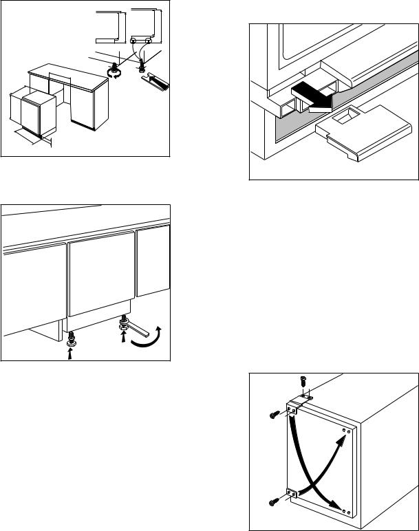
Place the appliance in the position where it is to be built in (Fig. 6).
The appliance is fitted with adjustable feet; screw the front and rear feet in or out to adjust the height of the appliance to that of the recess.
Keeping the appliance central in the recess, slide it in until its back touches the wall.
With a tape measure (or similar instrument), measure distance (A) between the top edge of the door and the top edge of the decorative panel, placing it next to the recess.
|
Fig. 6 |
|
A |
= |
= |
D467 |
|
Lay the panel face down (Fig. 7). Position the top bracket on the panel, making sure that there is an equal distance between it and the sides and that its distance from the top edge is equal to distance (A) less 1 cm.
Secure the bracket with the screws supplied.
Take care not to damage the front face of the panel whilst working.
|
Fig. 7 |
|
= |
|
|
= |
A |
|
-1cm |
||
|
||
D468 |
|
8
Insert the adjusting pins (B-Fig. 8) into their locations in the door and screw them in.
Fig. 8
 B
B 
D532
Hook the decorative panel onto the top part of the door, inserting the pins (B) (on the door) into the elongated holes (1) (in the top bracket fitted to the panel) (Fig. 9).
Insert the securing screws (C) through elongated holes (2) and fix the panel without tightening the screws (Fig. 9).
Fig. 9
1
B
C
2
D533
 Loading...