

Page 1

Configuration Guide
TL-R470T+/TL-R480T+
1910012201 REV9.0.0
June 2017
Page 2

CONTENTS
About This Guide
Intended Readers ................................................................................................................................................................1
Conventions ...........................................................................................................................................................................1
More Information .................................................................................................................................................................1
Viewing Status Information .............................................................................................. 2
System Status ....................................................................................................................................................................... 3
Traffic Statistics .................................................................................................................................................................. 4
Viewing the Interface Statistics .........................................................................................................................................................4
Viewing the IP Statistics .........................................................................................................................................................................5
Configuring Network ........................................................................................................... 7
Overview .................................................................................................................................................................................8
Supported Features .................................................................................................................................................................................8
WAN Configuration .............................................................................................................................................................9
Configuring the Number of WAN Ports .........................................................................................................................................9
Configuring the WAN Connection ...................................................................................................................................................9
LAN Configuration ............................................................................................................................................................ 21
Configuring the IP Address of the LAN Port ............................................................................................................................21
Configuring the DHCP Server ..........................................................................................................................................................22
Viewing the DHCP Client List ...........................................................................................................................................................24
IPTV Configuration ........................................................................................................................................................... 25
Configuring IPTV Based on IGMP ..................................................................................................................................................25
Configuring IPTV in Bridge Mode ..................................................................................................................................................26
Configuring IPTV in Custom Mode ...............................................................................................................................................26
MAC Configuration ........................................................................................................................................................... 29
Configuring MAC Address ................................................................................................................................................................29
Switch Configuration ....................................................................................................................................................... 31
Viewing the Statistics ...........................................................................................................................................................................31
Configuring Port Mirror ........................................................................................................................................................................32
Configuring Rate Control ...................................................................................................................................................................33
Configuring Port Config ......................................................................................................................................................................34
Viewing Port Status ...............................................................................................................................................................................35
VLAN Configuration ......................................................................................................................................................... 36
Page 3

Creating a VLAN ......................................................................................................................................................................................36
Configuring the PVID of a Port ........................................................................................................................................................37
IPv6 Configuration ............................................................................................................................................................ 39
Configuring the LAN ..............................................................................................................................................................................39
Configuring the WAN ............................................................................................................................................................................40
Configuring the Number of WAN Ports ........................................................................................................................40
Configuring the WAN Connection ...................................................................................................................................41
Configuring Preferences .................................................................................................49
Overview .............................................................................................................................................................................. 50
IP Group Configuration .................................................................................................................................................. 51
Adding IP Address Entries .................................................................................................................................................................51
Grouping IP Address Entries ............................................................................................................................................................52
Time Range Configuration ............................................................................................................................................. 53
Service Type Configuration .......................................................................................................................................... 55
Configuring Transmission...............................................................................................58
Transmission ...................................................................................................................................................................... 59
Overview ......................................................................................................................................................................................................59
Supported Features ..............................................................................................................................................................................59
NAT Configurations.......................................................................................................................................................... 61
Configuring the Multi-Nets NAT .....................................................................................................................................................61
Configuring the One-to-One NAT .................................................................................................................................................62
Configuring the Virtual Servers .......................................................................................................................................................63
Configuring the Port Triggering ......................................................................................................................................................64
Configuring the NAT-DMZ .................................................................................................................................................................65
Configuring the ALG .............................................................................................................................................................................65
Bandwidth Control Configuration ............................................................................................................................... 66
Session Limit Configurations ....................................................................................................................................... 68
Configuring Session Limit ..................................................................................................................................................................68
Viewing the Session Limit Information .......................................................................................................................................69
Load Balancing Configurations ................................................................................................................................... 70
Configuring the Load Balancing .....................................................................................................................................................70
Configuring the Link Backup ............................................................................................................................................................71
Configuring the Online Detection ..................................................................................................................................................72
Routing Configurations ................................................................................................................................................... 73
Configuring the Static Routing ........................................................................................................................................................73
Page 4

Configuring the Policy Routing .......................................................................................................................................................74
Viewing the Routing Table .................................................................................................................................................................75
Configuration Examples ................................................................................................................................................. 76
Example for Configuring NAT ..........................................................................................................................................................76
Network Requirements ..........................................................................................................................................................76
Network Topology ....................................................................................................................................................................76
Configuration Scheme ...........................................................................................................................................................76
Configuration Procedure ......................................................................................................................................................77
Example for Configuring Load Balancing ..................................................................................................................................79
Network Requirements ..........................................................................................................................................................79
Network Topology ....................................................................................................................................................................79
Configuration Scheme ...........................................................................................................................................................79
Configuration Procedure ......................................................................................................................................................80
Example for Configuring Virtual Server ......................................................................................................................................80
Network Requirements ..........................................................................................................................................................80
Network Topology ....................................................................................................................................................................81
Configuration Scheme ...........................................................................................................................................................81
Configuration Procedure ......................................................................................................................................................81
Example for Configuring Policy Routing ....................................................................................................................................82
Network Requirements ..........................................................................................................................................................82
Network Topology ....................................................................................................................................................................82
Configuration Scheme ...........................................................................................................................................................82
Configuration Procedure ......................................................................................................................................................82
Configuring Firewall ..........................................................................................................85
Firewall .................................................................................................................................................................................. 86
Overview ......................................................................................................................................................................................................86
Supported Features ..............................................................................................................................................................................86
Firewall Configuration ..................................................................................................................................................... 88
Anti ARP Spoofing ..................................................................................................................................................................................88
Adding IP-MAC Binding Entries ........................................................................................................................................88
Enable Anti ARP Spoofing ....................................................................................................................................................91
Configuring Attack Defense .............................................................................................................................................................93
Configuring MAC Filtering ..................................................................................................................................................................95
Configuring Access Control .............................................................................................................................................................96
Configuration Examples ................................................................................................................................................. 98
Example for Anti ARP Spoofing ......................................................................................................................................................98
Page 5

Network Requirements ..........................................................................................................................................................98
Configuration Scheme ...........................................................................................................................................................98
Configuration Procedure ......................................................................................................................................................99
Example for MAC Filtering ..............................................................................................................................................................101
Network Requirements .......................................................................................................................................................101
Configuration Scheme ........................................................................................................................................................102
Configuration Procedure ...................................................................................................................................................102
Example for Access Control .........................................................................................................................................................103
Network Requirements .......................................................................................................................................................103
Configuration Scheme ........................................................................................................................................................103
Configuration Procedure ...................................................................................................................................................104
Configuring Behavior Control ..................................................................................... 108
Behavior Control .............................................................................................................................................................109
Overview ...................................................................................................................................................................................................109
Supported Features ...........................................................................................................................................................................109
Behavior Control Configuration ................................................................................................................................110
Configuring Web Filtering ...............................................................................................................................................................110
Configure Web Group Filtering .......................................................................................................................................110
Configuring URL Filtering ...................................................................................................................................................113
Configuring Web Security ...............................................................................................................................................................115
Configuration Examples ...............................................................................................................................................117
Example for Access Control .........................................................................................................................................................117
Network Requirements .......................................................................................................................................................117
Configuration Scheme ........................................................................................................................................................117
Configuration Procedure ...................................................................................................................................................118
Example for Web Security ..............................................................................................................................................................121
Network Requirements .......................................................................................................................................................121
Configuration Scheme ........................................................................................................................................................122
Configuration Procedure ...................................................................................................................................................122
Configuring Authentication ......................................................................................... 123
Overview ............................................................................................................................................................................124
Typical Topology .................................................................................................................................................................................124
Portal Authentication Process .....................................................................................................................................................125
Supported Features ...........................................................................................................................................................................125
Supported Web Server .......................................................................................................................................................126
Page 6

Supported Authentication Server.................................................................................................................................126
Guest Resources....................................................................................................................................................................126
Local Authentication Configuration .........................................................................................................................127
Configuring the Authentication Page .......................................................................................................................................127
Configuring the Local User Account ........................................................................................................................................130
Configuring the Local User Account ...........................................................................................................................130
(Optional) Configuring the Backup of Local Users ..............................................................................................133
Radius Authentication Configuration ......................................................................................................................134
Configuring Radius Authentication ............................................................................................................................................134
Onekey Online Configuration .....................................................................................................................................137
Configuring the Authentication Page .......................................................................................................................................137
Guest Resources Configuration ................................................................................................................................139
Configuring the Five Tuple Type .................................................................................................................................................139
Configuring the URL Type...............................................................................................................................................................141
Viewing the Authentication Status ...........................................................................................................................143
Configuration Example .................................................................................................................................................144
Network Requirements .....................................................................................................................................................................144
Configuration Scheme .....................................................................................................................................................................144
Configuration Procedures ..............................................................................................................................................................145
Configuring the Authentication Page .........................................................................................................................145
Configuring Authentication Accounts for the Guests .......................................................................................146
Managing Services ......................................................................................................... 147
Services ..............................................................................................................................................................................148
Overview ...................................................................................................................................................................................................148
Support Features .................................................................................................................................................................................148
Dynamic DNS Configurations ....................................................................................................................................149
Configure and View Peanuthull DDNS .....................................................................................................................................149
Configure and View Comexe DDNS .........................................................................................................................................150
Configure and View DynDNS ........................................................................................................................................................151
Configure and View NO-IP DDNS ...............................................................................................................................................153
UPnP Configuration .......................................................................................................................................................155
Configuration Example for Dynamic DNS..............................................................................................................156
Network Requirement .......................................................................................................................................................................156
Configuration Scheme .....................................................................................................................................................................156
Configuration Procedure .................................................................................................................................................................156
Specifying the IP Address of the Host .......................................................................................................................156
Page 7

Configuring the DDNS function .....................................................................................................................................156
System Tools .................................................................................................................... 158
System Tools ....................................................................................................................................................................159
Overview ...................................................................................................................................................................................................159
Support Features .................................................................................................................................................................................159
Admin Setup .....................................................................................................................................................................160
Admin Setup ...........................................................................................................................................................................................160
Remote Management .......................................................................................................................................................................161
System Setting .....................................................................................................................................................................................161
Management .....................................................................................................................................................................163
Factory Default Restore ...................................................................................................................................................................163
Backup & Restore ................................................................................................................................................................................163
Reboot .......................................................................................................................................................................................................164
Firmware Upgrade ...............................................................................................................................................................................164
SNMP ...................................................................................................................................................................................165
Diagnostics .......................................................................................................................................................................166
Diagnostics .............................................................................................................................................................................................166
Configuring Ping .....................................................................................................................................................................166
Configuring Traceroute ......................................................................................................................................................167
Remote Assistance ............................................................................................................................................................................168
Time Settings ...................................................................................................................................................................169
Setting the System Time .................................................................................................................................................................169
Getting time from the Internet Automatically .........................................................................................................169
Setting the System Time Manually...............................................................................................................................170
Setting the Daylight Saving Time................................................................................................................................................170
Predefined Mode ....................................................................................................................................................................170
Recurring Mode ......................................................................................................................................................................171
Date Mode .................................................................................................................................................................................172
System Log .......................................................................................................................................................................173
Page 8

About This Guide Intended Readers
About This Guide
This Configuration Guide provides information for managing TL-R470T+/TL-R480T+
routers. Please read this guide carefully before operation.
Intended Readers
This Guide is intended for network managers familiar with IT concepts and network
terminologies.
Conventions
Some models featured in this guide may be unavailable in your country or region. For local
sales information, visit
http://www.tp-link.com
.
When using this guide, please notice that features of the router may vary slightly depending
on the model and software version you have. All screenshots, images, parameters and
descriptions documented in this guide are used for demonstration only.
The information in this document is subject to change without notice. Every effort has
been made in the preparation of this document to ensure accuracy of the contents, but
all statements, information, and recommendations in this document do not constitute
the warranty of any kind, express or implied. Users must take full responsibility for their
application of any products.
In this Guide, the following conventions are used:
The symbol
you make better use of your device.
Menu Name > Submenu Name > Tab page indicates the menu structure. Status >
Traffic Statistics > Interface Statistics means the Interface Statistics page under the
Traffic Statistics menu option that is located under the Status menu.
Bold font indicates a button, a toolbar icon, menu or menu item.
stands for Note. Notes contains suggestions or references that helps
More Information
The latest software and documentations can be found at Download Center at
www.tp-link.com/support
The Installation Guide (IG) can be found where you find this guide or inside the package
of the router.
Specifications can be found on the product page at
A Technical Support Forum is provided for you to discuss our products at
tp-link.com
Our Technical Support contact information can be found at the Contact Technical
Support page at
.
http://www.tp-link.com/support
.
http://www.tp-link.com
.
Configuration Guide 1
.
http://forum.
http://
Page 9

Part 1
Viewing Status Information
CHAPTERS
1. System Status
2. Traffic Statistics
Page 10
Viewing Status Information System Status
1
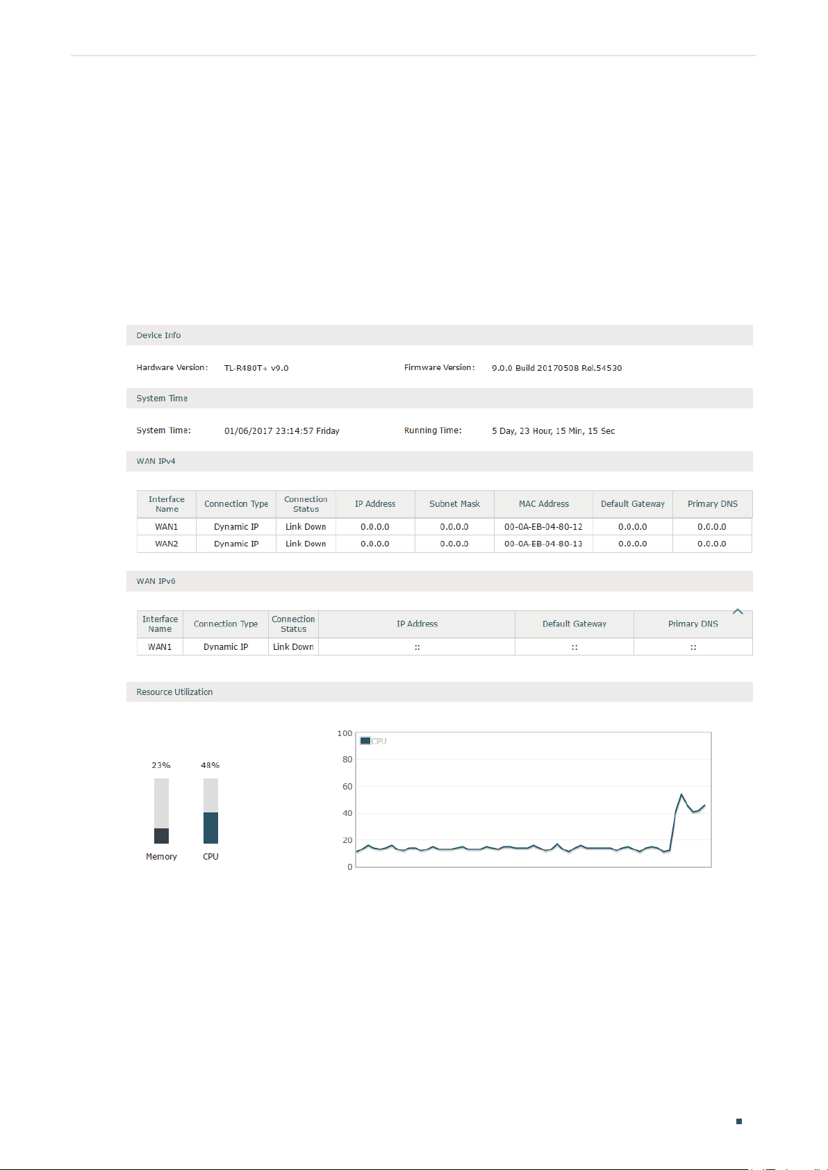
System Status
The System Status page displays the basic system information (like the hardware version,
firmware version and system time) and the running information (like the WAN interface
status, memory utilization and CPU utilization).
Choose the menu Status > System Status > System Status to load the following page.
Figure 1-1 System Status
Configuration Guide
3
Page 11
Viewing Status Information Traffic Statistics
2
Traffic Statistics
Traffic Statistics displays detailed information relating to the data traffic of interfaces and
IP addresses. You can monitor the traffic and locate faults according to this information.
With the Traffic Statistics function, you can:
View the traffic statistics on each interface.
Specify an IP address range, and view the traffic statistics of the IP addresses in this
range.
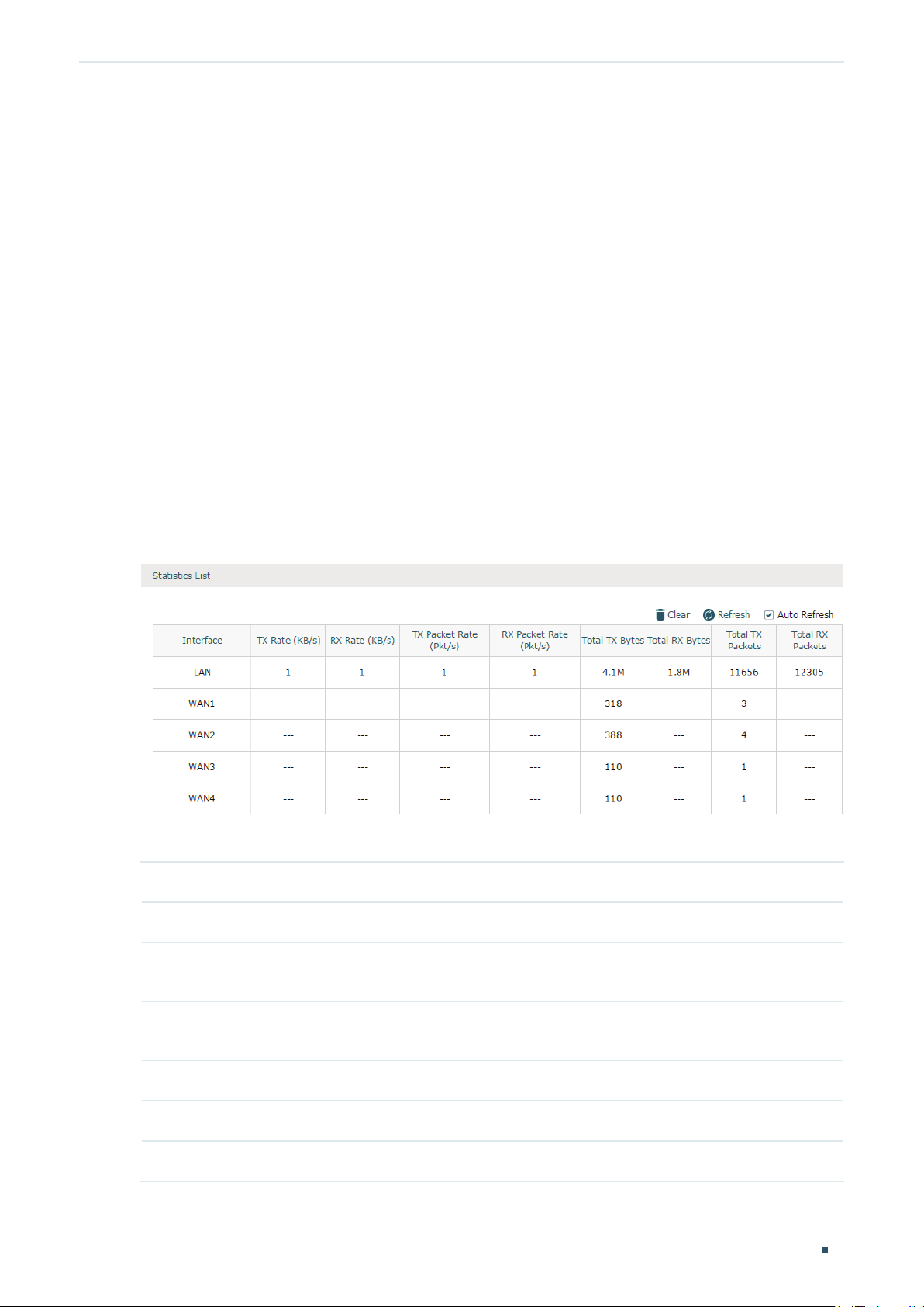
2.1 Viewing the Interface Statistics
Choose the menu Status > Traffic Statistics > Interface Statistics to load the following
page.
Figure 2-1 Interface Statistics
View the detailed traffic information of each interface in the statistics list.
TX Rate (KB/s) Displays the rate for transmitting data in kilobytes per second.
RX Rate (KB/s) Displays the rate for receiving data in kilobytes per second.
TX Packet Rate
(Pkt/s)
RX Packet Rate
(Pkt/s)
Total TX Bytes Displays the bytes of packets transmitted on the interface.
Total RX Bytes Displays the bytes of packets received on the interface.
Total TX Packets Displays the number of packets transmitted on the interface.
Displays the rate for transmitting data in packets per second.
Displays the rate for receiving data in packets per second.
Configuration Guide 4
Page 12
Viewing Status Information Traffic Statistics
Total RX Packets Displays the number of packets received on the interface.
You can enable Auto Refresh or click Refresh to get the latest statistics information, or
click Clear to clear the current statistics information.
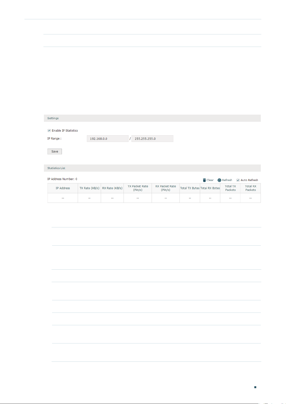
2.2 Viewing the IP Statistics
Choose the menu Status > Traffic Statistics > IP Statistics to load the following page.
Figure 2-2 IP Statistics
Follow these steps to view the traffic statistics of the specific IP addresses:
1) In the Settings section, enable IP Statistics and specify an IP range to monitor.
Enable IP
Statistics
IP Range Specify an IP range. The router will monitor the packets whose source IP
Check the box to enable IP Statistics.
addresses or destination IP addresses are in this range, and display the
statistics information in Statistics List.
2) In the Statistics List section, view the detailed traffic information of the IP addresses.
IP Address
Number
TX Rate (KB/s) Displays the rate for transmitting data in kilobytes per second.
RX Rate (KB/s) Displays the rate for receiving data in kilobytes per second.
TX Packet Rate
(Pkt/s)
RX Packet Rate
(Pkt/s)
Displays the number of active users whose IP address is in the specified IP
range.
Displays the rate for transmitting data in packets per second.
Displays the rate for receiving data in packets per second.
Configuration Guide
5
Page 13

Viewing Status Information Traffic Statistics
Total TX Bytes Displays the bytes of packets transmitted by the user who owns the IP address.
Total RX Bytes Displays the bytes of packets received by the user who owns the IP address.
Total TX Packets Displays the number of packets transmitted by the user who owns the IP
address.
Total RX Packets Displays the number of packets received by the user who owns the IP address.
You can enable Auto Refresh or click Refresh to get the latest statistics information, or
click Clear to clear the current statistics information.
Configuration Guide 6
Page 14

Part 2
Configuring Network
CHAPTERS
1. Overview
2. WAN Conguration
3. LAN Conguration
4. IPTV Conguration
5. MAC Conguration
6. Switch Conguration
7. VLAN Conguration
8. IPv6 Conguration
Page 15

Configuring Network Overview
1
Overview
The Network module provides basic router functions, including WAN connection, DHCP
service, VLAN, IPTV service and more.
1.1 Supported Features
WAN
The router can provide a maximum of four WAN ports. Each WAN port has its own internet
connection, providing link backup and load balancing.
LAN
For LAN configuration, you can configure the LAN IP address and DHCP (Dynamic Host
Configuration Protocol) server. With its DHCP server enabled, the router can automatically
assign IP addresses to hosts in the LAN.
IPTV
IPTV services is based on the Internet protocol, rather than through traditional satellite
signal or cable transmission.
The router supports three kinds of IPTV configuration according to your ISP
IPTV based on IGMP.
IPTV in Bridge mode.
IPTV in Custom mode.
MAC
You can change the default MAC address of the WAN port or LAN port according to your
needs.
Switch
The router supports some basic switch port management functions, like Flow Control and
Port Negotiation, to help you to monitor the traffic and manage the network effectively.
VLAN
The router supports 802.1Q VLAN, which can divide the LAN into multiple VLANs, helping
to manage the network more effectively.
:
IPv6
You can set up an IPv6 internet connection if your ISP provides IPv6 service.
Configuration Guide 8
Page 16
Configuring Network WAN Configuration
2
WAN Configuration
You can configure at most four WAN ports. Each WAN port can have its own WAN
connection, providing link backup and load balancing.
To complete WAN configuration, follow these steps:
1) Configure the number of WAN ports.
2) Configure the WAN connection.
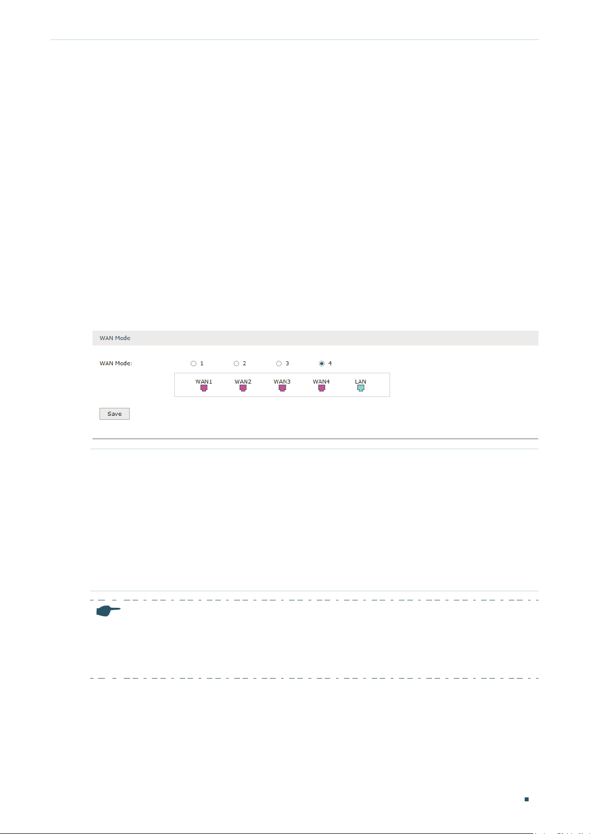
2.1 Configuring the Number of WAN Ports
Choose the menu Network > WAN > WAN Mode to load the following page.
Figure 2-1 Configuring the WAN Mode
WAN Mode Specify the number of WAN ports.
1: Configure physical interface 1 as WAN1.
2: Configure physical interface 1 and interface 2 as WAN1 and WAN2 respectively.
3: Configure physical interface 1, interface 2 and interface3 as WAN1, WAN2 and
WAN3 respectively.
4: Configure physical interface 1, interface 2, interface 3 and interface 4 as WAN1,
WAN2, WAN3 and WAN4 respectively.
Note:
When a WAN port is added, a port-related tab is automatically added; when a WAN port is de-
•
leted, the port-related tab is automatically deleted.
The router will reboot after switching the WAN mode.
•
2.2 Configuring the WAN Connection
The router supports six connection types: Static IP, Dynamic IP, PPPoE, L2TP, PPTP and
BigPond Cable, you can choose one according to the service provided by your ISP.
Configuration Guide
9
Page 17
Configuring Network WAN Configuration
Static IP: If your ISP provides you with a fixed IP address and the corresponding
parameters, choose Static IP.
Dynamic IP: If your ISP automatically assigns the IP address and the corresponding
parameters, choose Dynamic IP.
PPPoE: If your ISP provides you with a PPPoE account, choose PPPoE.
L2TP: If your ISP provides you with an L2TP account, choose L2TP.
PPTP: If your ISP provides you with a PPTP account, choose PPTP.
BigPond Cable: If your ISP provides you with a BigPond Cable account, choose BigPond
Cable. BigPond Cable is only available for Australian users.
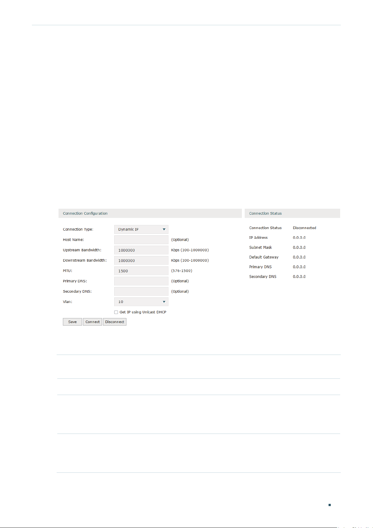
Configuring the Dynamic IP
Choose the menu Network > WAN > WAN to load the following page.
Figure 2-2 Configuring the Dynamic IP
In the Connection Configuration section, select the connection type as Dynamic IP. Enter
the corresponding parameters and click Save.
Connection Type Choose the connection type as Dynamic IP if your ISP automatically assigns the IP
address.
Host Name Optional. Enter a name for the router. It is null by default.
Upstream
Bandwidth
Downstream
Bandwidth
Specify the upstream bandwidth of the WAN port. The value configured here is the
upper limit of the “Maximum Upstream Bandwidth” on Transmission > Bandwidth
Control > Bandwidth Control page, to make “Bandwidth Control” take effect, please
ensure this parameter is set correctly.
Specify the downstream bandwidth of the WAN port. The value configured here is the
lower limit of the “Maximum Downstream Bandwidth” on Transmission > Bandwidth
Control > Bandwidth Control page, to make “Bandwidth Control” take effect, please
ensure this parameter is set correctly.
Configuration Guide 10
Page 18
Configuring Network WAN Configuration
MTU Specify the MTU (Maximum Transmission Unit) of the WAN port.
MTU is the maximum data unit transmitted in the physical network. When Dynamic
IP is selected, MTU can be set in the range of 576-1500 bytes. The default value is
1500.
Primary/
Secondary DNS
VLAN Add the WAN port to a VLAN. Generally, you don’t need to manually configure it
Get IP using
Unicast DHCP
Connect/
Disconnect
Optional. Enter the IP address of the DNS server provided by your ISP.
unless required by your ISP.
By default, the WAN port is automatically assigned to a VLAN, and the egress rule of
the VLAN is UNTAG, so the packets are transmitted by the WAN port without VLAN
tags. If you want the WAN port to transmit packets with VLAN tag, you need to create
the corresponding VLAN first and configure its egress rule as TAG, then manually
add the WAN port to that VLAN. To create VLANs, go to Network > VLAN > VLAN.
Note: When using the IPTV function, either in Bridge mode or Custom mode,
the router will automatically create corresponding VLANs after you finished the
configuration, and add port 1 (WAN 1) to the VLANs. Users cannot then manually
select the VLAN that WAN 1 belongs to.
The broadcasting requirement may not be supported by a few ISPs. Select this
option if you can not get the IP address from your ISP even with a normal network
connection. This option is not required generally.
Click the button to active/terminate the connection.
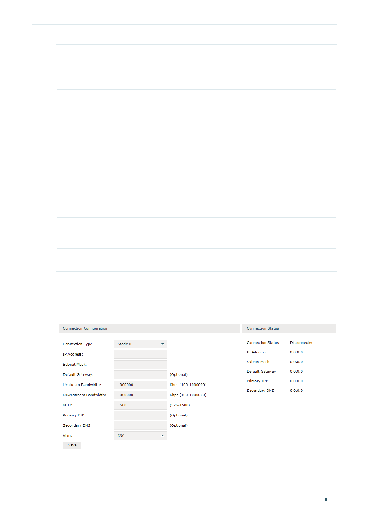
Configuring the Static IP
Choose the menu Network > WAN > WAN to load the following page.
Figure 2-3 Configuring the Static IP
In Connection Configuration section, select the connection type as Static IP. Enter the
corresponding parameters and click Save.
Configuration Guide
11
Page 19

Configuring Network WAN Configuration
Connection Type Choose the connection type as Static IP if your ISP has offered you a fixed IP
address.
IP Address Enter the IP address provided by your ISP.
Subnet Mask Enter the subnet mask provided by your ISP.
Default Gateway Enter the default gateway provided by your ISP.
Upstream
Bandwidth
Downstream
Bandwidth
MTU Specify the MTU (Maximum Transmission Unit) of the WAN port.
Primary/
Secondary DNS
VLAN Add the WAN port to a VLAN. Generally, you don’t need to manually configure it
Specify the downstream bandwidth of the WAN port. The value configured here is the
lower limit of the “Maximum Downstream Bandwidth” on Transmission > Bandwidth
Control > Bandwidth Control page, to make “Bandwidth Control” take effect, please
ensure this parameter is set correctly.
Specify the downstream bandwidth of the WAN port. The value configured here is the
lower limit of the “Maximum Downstream Bandwidth” on Transmission > Bandwidth
Control > Bandwidth Control page, to make “Bandwidth Control” take effect, please
ensure this parameter is set correctly.
MTU is the maximum data unit transmitted in the physical network. When Static IP is
selected, MTU can be set in the range of 576-1500 bytes. The default value is 1500.
Optional. Enter the IP address of the DNS server provided by your ISP.
unless required by your ISP.
By default, the WAN port is automatically assigned to a VLAN, and the egress rule of
the VLAN is UNTAG, so the packets are transmitted by the WAN port without VLAN
tags. If you want the WAN port to transmit packets with VLAN tag, you need to create
the corresponding VLAN first and configure its egress rule as TAG, then manually
add the WAN port to that VLAN. To create VLANs, go to Network > VLAN > VLAN.
Note: When using the IPTV function, either in Bridge mode or Custom mode,
the router will automatically create corresponding VLANs after you finished the
configuration, and add port 1 (WAN1) to the VLANs. Users cannot then manually
select the VLAN that WAN 1 belongs to.
Configuration Guide 12
Page 20
Configuring Network WAN Configuration
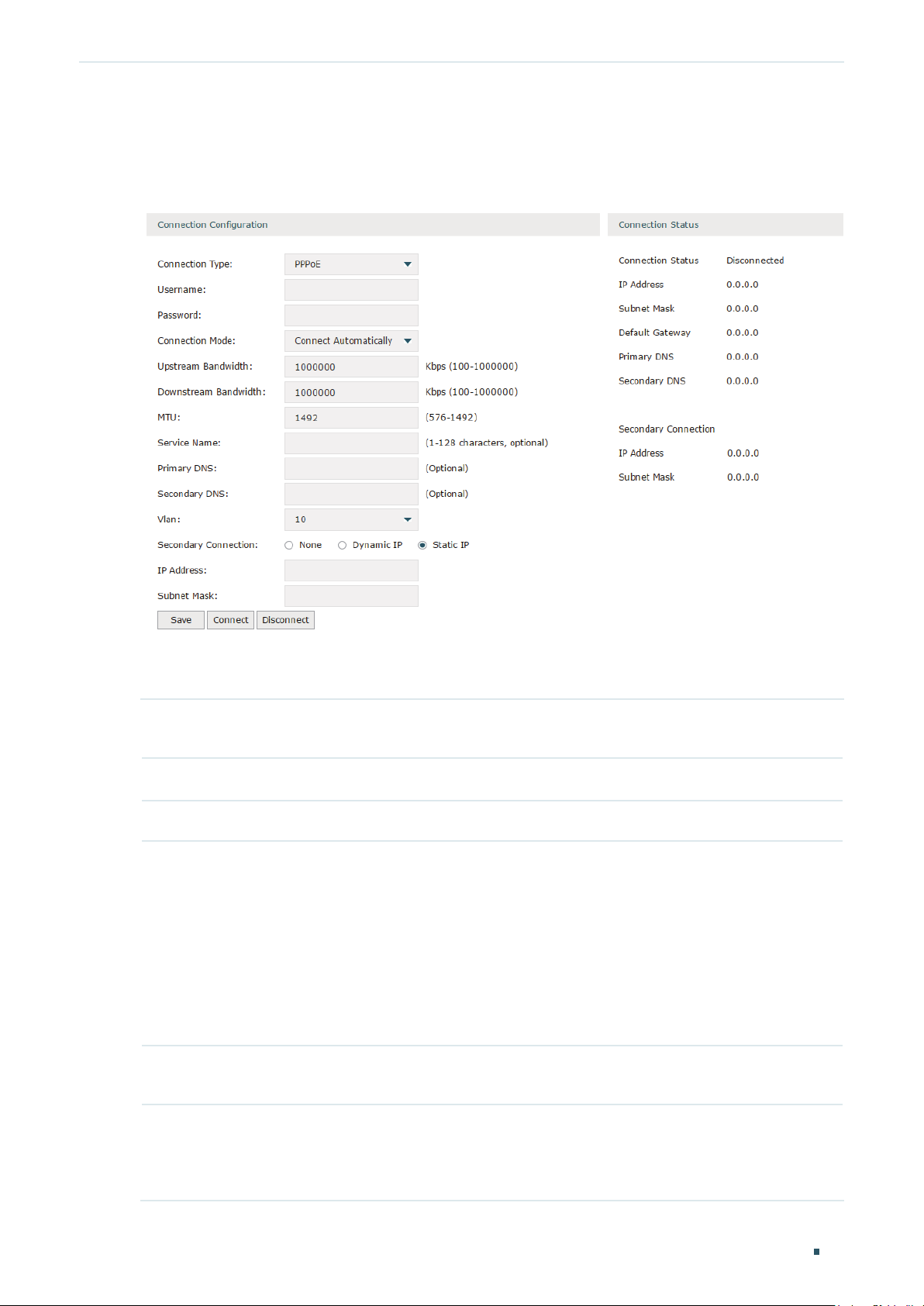
Configuring the PPPoE
Choose the menu Network > WAN > WAN to load the following page.
Figure 2-4 Configuring the PPPoE
In the Connection Configuration section, select the connection type as PPPoE. Enter the
corresponding parameters and click Save.
Connection Type Choose the connection type as PPPoE if your ISP provides you with a PPPoE
account.
Username Enter the PPPoE username provided by your ISP.
Password Enter the PPPoE password provided by your ISP.
Connection
Mode
Time Choose the effective time range when the Connection Mode is chosen as Time-
Choose the connection mode, including Connect Automatically, Connect Manually
and Time-Based.
Connect Automatically: The router will activate the connection automatically when
the router reboots or the connection is down.
Connect Manually: You can manually activate or terminate the connection.
Time-Based: During the specified period, the router will automatically activate the
connection.
Based. To create the time range, go to Preferences > Time Range > Time Range.
Upstream
Bandwidth
Specify the upstream bandwidth of the WAN port. The value configured here is the
upper limit of the “Maximum Upstream Bandwidth” on Transmission > Bandwidth
Control > Bandwidth Control page, to make “Bandwidth Control” take effect, please
ensure this parameter is set correctly.
Configuration Guide
13
Page 21

Configuring Network WAN Configuration
Downstream
Bandwidth
MTU Specify the MTU (Maximum Transmission Unit) of the WAN port.
Service Name Optional. Enter the service name. This parameter is not required unless provided by
Primary/
Secondary DNS
VLAN Add the WAN port to a VLAN. Generally, you don’t need to manually configure it
Specify the downstream bandwidth of the WAN port. The value configured here is the
lower limit of the “Maximum Downstream Bandwidth” on Transmission > Bandwidth
Control > Bandwidth Control page, to make “Bandwidth Control” take effect, please
ensure this parameter is set correctly.
MTU is the maximum data unit transmitted in the physical network. When PPPoE is
selected, MTU can be set in the range of 576-1492 bytes. The default value is 1492.
your ISP. It is null by default.
Optional. Enter the IP address of the DNS server provided by your ISP.
unless required by your ISP.
By default, the WAN port is automatically assigned to a VLAN, and the egress rule of
the VLAN is UNTAG, so the packets are transmitted by the WAN port without VLAN
tags. If you want the WAN port to transmit packets with VLAN tag, you need to create
the corresponding VLAN first and configure its egress rule as TAG, then manually
add the WAN port to that VLAN. To create VLANs, go to Network > VLAN > VLAN.
Secondary
Connection
Connect/
Disconnect
Note: When using the IPTV function, either in Bridge mode or Custom mode,
the router will automatically create corresponding VLANs after you finished the
configuration, and add port 1 (WAN 1) to the VLANs. Users cannot then manually
select the VLAN that WAN 1 belongs to.
Secondary connection is required by some ISPs. Select the connection type required
by your ISP.
None: Select this if the secondary connection is not required by your ISP.
Dynamic IP: Select this if your ISP automatically assigns the IP address and subnet
mask for the secondary connection.
Static IP: Select this if your ISP provides you with a fixed IP address and subnet mask
for the secondary connection.
Click the button to active/terminate the connection.
Configuration Guide 14
Page 22

Configuring Network WAN Configuration
Configuring the L2TP
Choose the menu Network > WAN > WAN to load the following page.
Figure 2-5 Configuring the L2TP
In the Connection Configuration section, select the connection type as L2TP. Enter the
corresponding parameters and click Save.
Connection Type Choose the connection type as L2TP if your ISP provides you with an L2TP account.
Username Enter the L2TP username provided by your ISP.
Password Enter the L2TP password provided by your ISP.
Connection
Mode
Time Choose the effective time range when the Connection Mode is chosen as Time-
Choose the connection mode, including Connect Automatically, Connect Manually
and Time-Based.
Connect Automatically: The router will activate the connection automatically when
the router reboots or the connection is down.
Connect Manually: You can manually activate or terminate the connection.
Time-Based: During the specified period, the router will automatically activate the
connection.
Based. To create the time range, go to Preferences > Time Range > Time Range.
Configuration Guide
15
Page 23

Configuring Network WAN Configuration
Upstream
Bandwidth
Downstream
Bandwidth
MTU Specify the MTU (Maximum Transmission Unit) of the WAN port.
Primary/
Secondary DNS
VLAN Add the WAN port to a VLAN. Generally, you don’t need to manually configure it
Specify the upstream bandwidth of the WAN port. The value configured here is the
upper limit of the “Maximum Upstream Bandwidth” on Transmission > Bandwidth
Control > Bandwidth Control page, to make “Bandwidth Control” take effect, please
ensure this parameter is set correctly.
Specify the downstream bandwidth of the WAN port. The value configured here is the
lower limit of the “Maximum Downstream Bandwidth” on Transmission > Bandwidth
Control > Bandwidth Control page, to make “Bandwidth Control” take effect, please
ensure this parameter is set correctly.
MTU is the maximum data unit transmitted in the physical network. When L2TP is
selected, MTU can be set in the range of 576-1460 bytes. The default value is 1460.
Optional. Enter the IP address of the DNS server provided by your ISP.
unless required by your ISP.
By default, the WAN port is automatically assigned to a VLAN, and the egress rule of
the VLAN is UNTAG, so the packets are transmitted by the WAN port without VLAN
tags. If you want the WAN port to transmit packets with VLAN tag, you need to create
the corresponding VLAN first and configure its egress rule as TAG, then manually
add the WAN port to that VLAN. To create VLANs, go to Network > VLAN > VLAN.
Note: When using the IPTV function, either in Bridge mode or Custom mode,
the router will automatically create corresponding VLANs after you finished the
configuration, and add port 1 (WAN 1) to the VLANs. Users cannot then manually
select the VLAN that WAN 1 belongs to.
Secondary
Connection
VPN Server/
Domain Name
IP Address Enter the IP address provided by your ISP for the secondary connection.
Subnet Mask Enter the subnet mask provided by your ISP for the secondary connection.
Default Gateway Enter the default gateway provided by your ISP for the secondary connection.
Primary/
Secondary DNS
Connect/
Disconnect
Select the secondary connection type provided by your ISP
The secondary connection is required for L2TP connection. The router will get
some necessary information after the secondary connection succeeded. These
information will be used in the L2TP connection process.
Enter the VPN Server/Domain Name provided by your ISP.
Enter the primary/secondary DNS provided by your ISP for the secondary
connection.
Click the button to active/terminate the connection.
Configuration Guide 16
Page 24
Configuring Network WAN Configuration
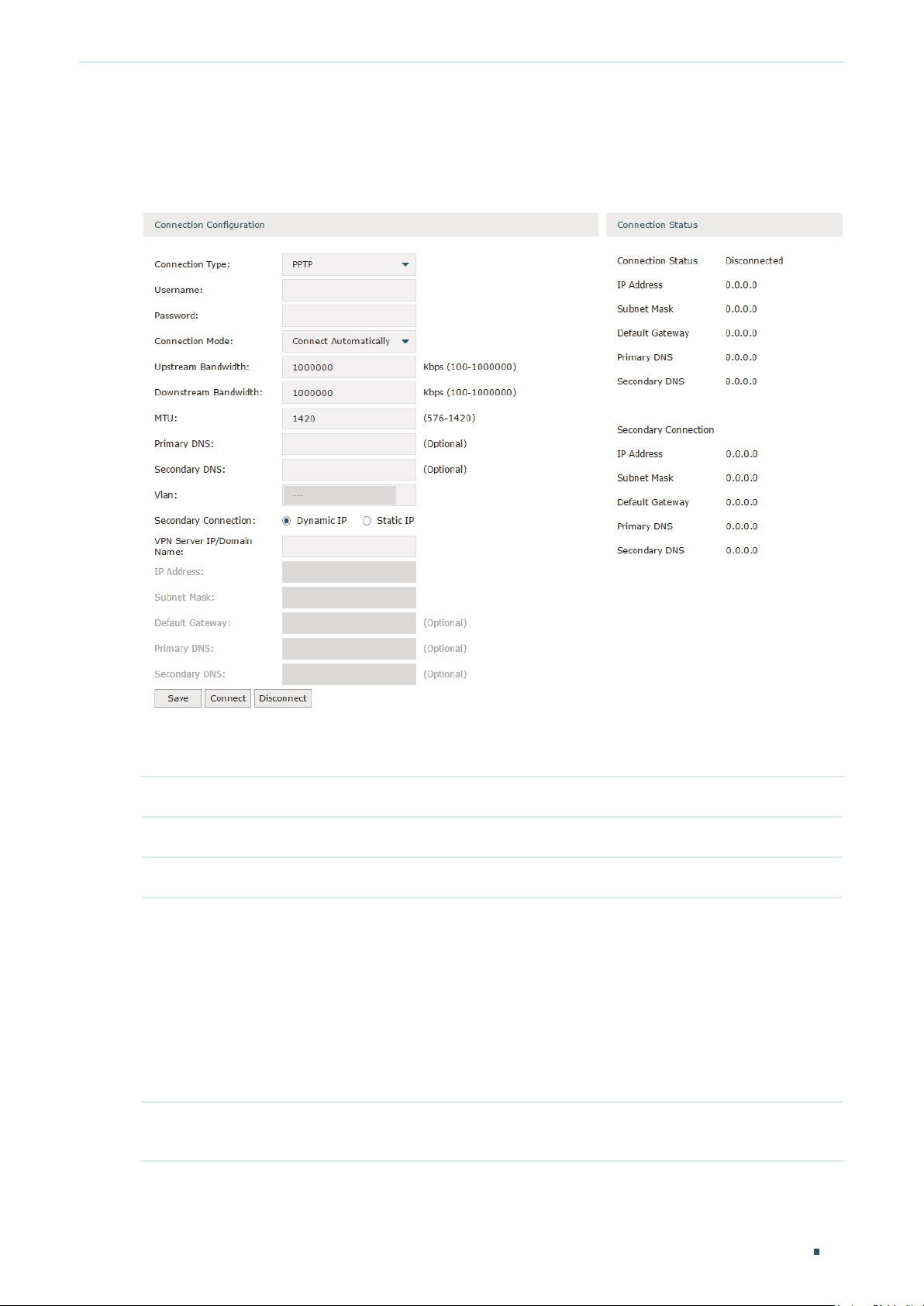
Configuring the PPTP
Choose the menu Network > WAN > WAN to load the following page.
Figure 2-6 Configuring the PPTP
In Connection Configuration section, select the connection type as PPTP. Enter the
corresponding parameters and click Save.
Connection Type Choose the connection type as PPTP if your ISP provides you with a PPTP account.
Username Enter the PPTP username provided by your ISP.
Password Enter the PPTP password provided by your ISP.
Connection
Mode
Time Choose the effective time range when the Connection Mode is chosen as Time-
Choose the connection mode, including Connect Automatically, Connect Manually
and Time-Based.
Connect Automatically: The router will activate the connection automatically when
the router reboots or the connection is down.
Connect Manually: You can manually activate or terminate the connection.
Time-Based: During the specified period, the router will automatically activate the
connection.
Based. To create the time range, go to Preferences > Time Range > Time Range.
Configuration Guide
17
Page 25

Configuring Network WAN Configuration
Upstream
Bandwidth
Downstream
Bandwidth
MTU Specify the MTU (Maximum Transmission Unit) of the WAN port.
Primary/
Secondary DNS
VLAN Add the WAN port to a VLAN. Generally, you don’t need to manually configure it
Specify the upstream bandwidth of the WAN port. The value configured here is the
upper limit of the “Maximum Upstream Bandwidth” on Transmission > Bandwidth
Control > Bandwidth Control page, to make “Bandwidth Control” take effect, please
ensure this parameter is set correctly.
Specify the downstream bandwidth of the WAN port. The value configured here is the
lower limit of the “Maximum Downstream Bandwidth” on Transmission > Bandwidth
Control > Bandwidth Control page, to make “Bandwidth Control” take effect, please
ensure this parameter is set correctly.
MTU is the maximum data unit transmitted in the physical network. When PPTP is
selected, MTU can be set in the range of 576-1420 bytes. The default value is 1420.
Optional. Enter the IP address of the DNS server provided by your ISP.
unless required by your ISP.
By default, the WAN port is automatically assigned to a VLAN by default, and the
egress rule of the VLAN is UNTAG, so the packets are transmitted by the WAN port
without VLAN tags. If you want the WAN port to transmit packets with VLAN tag, you
need to create the corresponding VLAN first and configure its egress rule as TAG,
then manually add the WAN port to that VLAN. To create VLANs, go to Network >
VLAN > VLAN.
Note: When using the IPTV function, either in Bridge mode or Custom mode,
the router will automatically create corresponding VLANs after you finished the
configuration, and add port 1 (WAN 1) to the VLANs. Users cannot then manually
select the VLAN that WAN 1 belongs to.
Secondary
Connection
VPN Server/
Domain Name
IP Address Enter the IP address provided by your ISP for the secondary connection.
Subnet Mask Enter the subnet mask provided by your ISP for the secondary connection.
Default Gateway Enter the default gateway provided by your ISP for the secondary connection.
Primary/
Secondary DNS
Connect/
Disconnect
Select the secondary connection type provided by your ISP
The secondary connection is required for PPTP connection. The router will get
some necessary information after the secondary connection succeeded. These
information will be used in the PPTP connection process.
Enter the VPN Server/Domain Name provided by your ISP.
Enter the primary/secondary DNS provided by your ISP for the secondary
connection.
Click the button to active/terminate the connection.
Configuration Guide 18
Page 26
Configuring Network WAN Configuration
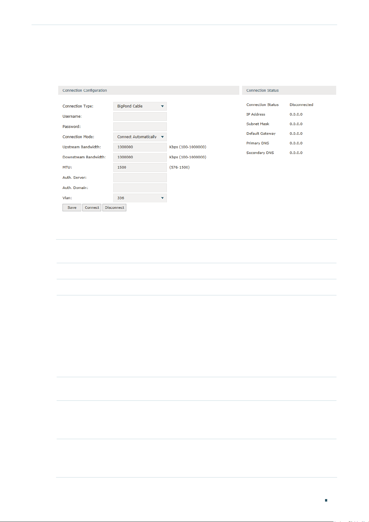
Configuring the BigPond Cable
Choose the menu Network > WAN > WAN to load the following page.
Figure 2-7 Configuring the BigPond Cable
In Connection Configuration section, select the connection type as BigPond Cable. Enter
the corresponding parameters and click Save.
Connection Type Choose the connection type as BigPond if your ISP provides you with a BigPond
account.
Username Enter the BigPond username provided by your ISP.
Password Enter the BigPond password provided by your ISP.
Connection
Mode
Time Choose the effective time range when the Connection Mode is chosen as Time-
Choose the connection mode, including Connect Automatically, Connect Manually
and Time-Based.
Connect Automatically: The router will activate the connection automatically when
the router reboots or the connection is down.
Connect Manually: You can manually activate or terminate the connection.
Time-Based: During the specified period, the router will automatically activate the
connection.
Based. To create the time range, go to Preferences > Time Range > Time Range.
Upstream
Bandwidth
Downstream
Bandwidth
Specify the upstream bandwidth of the WAN port. The value configured here is the
upper limit of the “Maximum Upstream Bandwidth” on Transmission > Bandwidth
Control > Bandwidth Control page, to make “Bandwidth Control” take effect, please
ensure this parameter is set correctly.
Specify the downstream bandwidth of the WAN port. The value configured here is the
lower limit of the “Maximum Downstream Bandwidth” on Transmission > Bandwidth
Control > Bandwidth Control page, to make “Bandwidth Control” take effect, please
ensure this parameter is set correctly.
Configuration Guide
19
Page 27

Configuring Network WAN Configuration
MTU Specify the MTU (Maximum Transmission Unit) of the WAN port.
MTU is the maximum data unit transmitted in the physical network. When BigPond
Cable is selected, MTU can be set in the range of 576-1500 bytes. The default value
is 1500.
Auth.Server Enter the authenticating server’s IP address or hostname.
Auth.Domain Enter the server's domain name suffix (based on your location). For example, nsw.
bigpond.net.au for NSW/ACT, vic.bigpond.net.au for VIC/TAS/WA/SA/NT, or qld.
bigpond.net.au for QLD.
VLAN Add the WAN port to a VLAN. Generally, you don’t need to manually configure it
unless required by your ISP.
By default, the WAN port is automatically assigned to a VLAN, and the egress rule of
the VLAN is UNTAG, so the packets are transmitted by the WAN port without VLAN
tags. If you want the WAN port to transmit packets with VLAN tag, you need to create
the corresponding VLAN first and configure its egress rule as TAG, then manually
add the WAN port to that VLAN. To create VLANs, go to Network > VLAN > VLAN.
Connect/
Disconnect
Note: When using the IPTV function, either in Bridge mode or Custom mode,
the router will automatically create corresponding VLANs after you finished the
configuration, and add port 1 (WAN 1) to the VLANs. Users cannot then manually
select the VLAN that WAN 1 belongs to.
Click the button to active/terminate the connection.
Configuration Guide 20
Page 28
Configuring Network LAN Configuration
3
LAN Configuration
The LAN port is used to connect to the LAN clients, and works as the default gateway
for these clients. You can configure the DHCP server for the LAN clients, and clients will
automatically be assigned to IP addresses if the method of obtaining IP addresses is set as
“Obtain IP address automatically”.
For LAN configuration, you can:
Configure the IP address of the LAN port.
Configure the DHCP server.
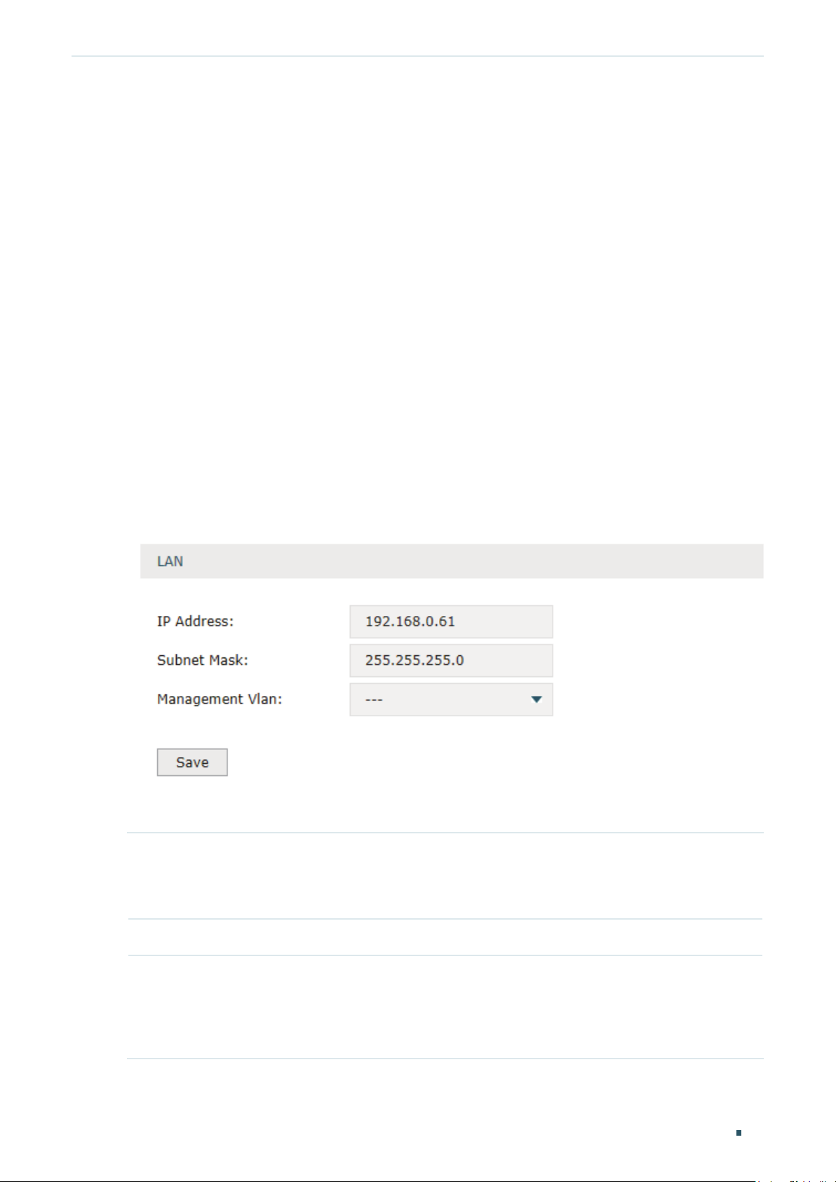
3.1 Configuring the IP Address of the LAN Port
Choose the menu Network > LAN > LAN to load the following page.
Figure 3-1 Configuring the LAN IP Address
Enter the IP address of the LAN port, and click Save.
IP Address Enter the IP address of the LAN port.
This IP address is the default gateway of the LAN clients, and the IP addresses of all
the LAN clients should be in the same subnet with this LAN IP address.
Subnet Mask Enter the subnet mask of the LAN port.
Management
Vlan
Specify the management VLAN.
If you set a management VLAN here, then only the clients in the specified VLAN can
access and manage the router. The default value is “---“, which means no VLAN is
selected, and any client in the LAN can access and manage the router.
Configuration Guide
21
Page 29
Configuring Network LAN Configuration
Note:
Changing the IP address of LAN port will automatically redirect the browser to the new man-
•
agement page. If the redirecting failed, please try to reconnect your PC to the router to automatically get a new IP address, or configure a proper static IP address manually.
Changing the IP address of the LAN port may affect some related functions, like the IP pool of
•
the DHCP server.
3.2 Configuring the DHCP Server
You can configure an IP address pool for the DHCP server to assign IP addresses. When
clients send requests to the DHCP server, the server will automatically assign IP addresses
and the corresponding parameters to the clients. Moreover, if you want to reserve an IP
address for a certain client, you can use Address Reservation to bind the IP address with
the client’s MAC address, and the bound IP address will always be assigned to that client.
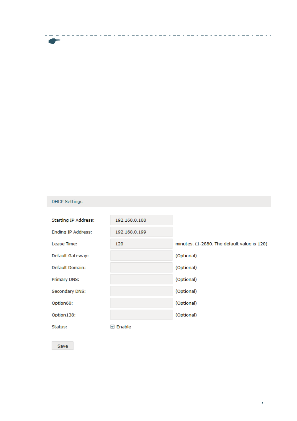
Configuring the DHCP Server
Choose the menu Network > LAN > DHCP Server to load the following page.
Figure 3-2 Configuring the DHCP Server
Configure the parameters of the DHCP server, then click Save.
Configuration Guide 22
Page 30

Configuring Network LAN Configuration
Starting IP
Address
Ending IP
Address
Lease Time Specify the lease time for DHCP clients.
Default Gateway Optional. It is recommended to enter the IP address of the LAN port.
Default Domain Optional. Enter the domain name of your network.
Enter the starting IP address of the DHCP server’s IP pool. The IP pool defines the IP
range that can be assigned to the clients in the LAN.
Note: The starting IP address should be in the same subnet with the IP address of the
LAN port.
Enter the ending IP address of the DHCP server’s IP pool. The ending IP address
should be greater than the starting IP address.
Note: The ending IP address should be in the same subnet with the IP address of the
LAN port.
Lease time defines how long the clients can use the IP address assigned by the DHCP
server. Generally, the client will automatically request the DHCP server for extending
the lease time before the lease expired. If the request failed, the client will have to stop
using that IP address when the lease finally expired, and try to get a new IP address
from the other DHCP servers.
Primary
Secondary DNS
Option60 Optional. Specify the option 60 for device identification. Mostly it is used under the
Option 138 Optional. Specify the option 138, which can be configured as the management IP
Status Check the box to enable the DHCP server.
/
Configuring the Address Reservation
Optional. Enter the DNS server address provided by your ISP. If you are not clear,
please consult your ISP.
scenario where the clients apply for different IP addresses from different servers
according to the needs. By default, it is TP-LINK.
If a client requests option 60, the server will respond a packet containing the option
60 configured here. And then the client will compare the received option 60 with its
own. If they are the same, the client will accept the IP address assigned by the server,
otherwise the assigned IP address will not be accepted.
address of an AC (Access Controller) device. If the APs in the local network request
this option, the server will respond a packet containing this option to inform the APs
of the AC’s IP address.
Choose the menu Network > LAN > Address Reservation and click Add to load the
following page.
Configuration Guide
23
Page 31

Configuring Network LAN Configuration
Figure 3-3 Configuring the Address Reservation
Enter the MAC address of the client and the IP address to be reserved, then click OK.
MAC Address Enter the MAC address of the client.
IP Address Enter the IP address to be reserved.
Description Optional. Enter a brief description for the entry. Up to 32 characters can be entered.
Export to IPMAC Binding
Status Check the box to enable this entry.
Optional. Check the box to export this binding entry to IP-MAC Binding List on Firewall
> Anti ARP Spoofing > IP-MAC Binding page.
3.3 Viewing the DHCP Client List
Choose the menu Network > LAN > DHCP Client List to load the following page.
Figure 3-4 Viewing the DHCP Client List
Here you can view the DHCP client list.
Client Name Displays the name of the client.
MAC Address Displays the MAC address of the client.
Assigned IP
Address
Lease Time Displays the remaining lease time of the assigned IP address. After the lease expires,
Displays the IP address assigned to the client.
the IP address will be re-assigned.
Configuration Guide 24
Page 32

Configuring Network IPTV Configuration
4
IPTV Configuration
You can configure IPTV according to the type of IPTV service provided by your ISP:
Configure IPTV based on IGMP.
Configure IPTV in Bridge mode.
Configure IPTV in Custom mode.
4.1 Configuring IPTV Based on IGMP
Some ISPs provide IPTV service based on IGMP technology. In this scenario, you can just
enable IGMP snooping and IGMP proxy, and connect your STB (Set-Top Box) to any LAN
port of the router. The IPTV stream will then be transmitted to the corresponding LAN port.
Choose the menu Network > IPTV> IPTV to load the following page.
Figure 4-1 Configuring IPTV Based on IGMP
Enable IGMP Snooping and IGMP Proxy, and choose the IGMP version, then click Save.
IGMP Snooping Check the box to enable IGMP Snooping.
Without IGMP Snooping, the router will broadcast multicast stream to all LAN ports,
even though some LAN ports are not connected to any multicast member.
With IGMP Snooping enabled, the LAN ports listen IGMP packets transmitted between
the router and the clients and build a multicast table. The multicast table records the
multicast members and the corresponding connected LAN port. So the multicast
stream will be transmitted to only the ports that connected to multicast members.
IGMP Proxy Check the box to enable IGMP Proxy.
IGMP Proxy sends IGMP querier packets to the LAN ports to detect if there is any
multicast member connected to the LAN ports.
IGMP Version Choose the IGMP version as V2 or V3. The default is IGMP V2.
Configuration Guide
25
Page 33

Configuring Network IPTV Configuration
4.2 Configuring IPTV in Bridge Mode
If your ISP doesn’t provide any parameters and the IPTV service is not based on IGMP
technology, you can enable IPTV function and choose the Bridge mode, then specify a port
to connect IPTV set-top box.
Choose the menu Network > IPTV> IPTV to load the following page.
Figure 4-2 Configuring the Bridge Mode
Enable IPTV function, choose the mode as Bridge, and choose a LAN port to connect to the
IPTV set-top box, then click Save.
IPTV Check the box to enable IPTV function.
Mode Choose the mode as Bridge.
In Bridge mode, the LAN port chosen to connect to the IPTV becomes a dedicated
port for IPTV service.
Port Mode Specify the service to be supported by the LAN port.
Internet: Specify the port to support only internet service. If you want to access the
internet, you should connect your host to this port.
IPTV: Specify the port to only support IPTV service. If you want to use IPTV, you
should connnect your IPTV set-top box to this port.
4.3 Configuring IPTV in Custom Mode
If your ISP supports Triple-Play service, i.e., providing internet, VoIP and IPTV services over
one single broadband connection, you can configure IPTV in Custom mode.
In Triple-Play, services are labeled with different VLAN tags specified by the ISP. When
the WAN port receives packets, it will forward the packets to the corresponding LAN port
according to the VLAN tag.
Choose the menu Network > IPTV> IPTV to load the following page.
Configuration Guide 26
Page 34

Configuring Network IPTV Configuration
Figure 4-3 Configuring the Custom Mode
Follow these steps to configure IPTV in Custom mode:
1) Enable IPTV function and choose the mode as Custom.
IPTV Check the box to enable IPTV function.
Mode Choose the mode as Custom.
In Custom mode, the services are labeled with different VLAN tags, which is
specified by the ISP. The WAN port will forward the packets to its corresponding
LAN port.
2) Enter the parameters provided by your ISP, including the VLAN IDs and priorities of
different services.
Internet VLAN ID Enter the VLAN ID of the internet service. It is provided by your ISP.
Internet VLAN
Priority
802.1Q Tag Optional. Check the box and the egress internet packets of WAN 1 port will be
Enter the VLAN priority of the internet service. It is provided by your ISP.
tagged.
IP-Phone VLAN IDEnter the VLAN ID of the IP-Phone service. It is provided by your ISP.
IP-Phone VLAN
Priority
IPTV VLAN ID Enter the VLAN ID of the IPTV service. It is provided by your ISP.
Enter the VLAN priority of the IP-Phone service. It is provided by your ISP.
Configuration Guide
27
Page 35

Configuring Network IPTV Configuration
IPTV VLAN
Priority
IPTV Multicast
VLAN ID
IPTV Multicast
VLAN Priority
Enter the VLAN priority of the IPTV service. It is provided by your ISP.
Enter the VLAN ID of the IPTV multicast service. It is provided by your ISP.
Enter the VLAN priority of the IPTV multicast service. It is provided by your ISP.
3) Specify the service to support for the LAN port.
Port Mode Specify the service to be supported by the LAN port.
Internet: Specify the port to support only Internet service. If you want to surf the
internet, you should connect your host to this port.
IP-Phone: Specify the port to support only IP-Phone service. If you want to make
an IP-Phone call, you should connect your IP-Phone to this port.
IPTV: Specify the port to only support IPTV service. If you want to use IPTV, you
should connnect your IPTV set-top box to this port.
Note:
Among the WAN ports, only WAN 1 supports IPTV service. So if you want to use IPTV function,
•
connect your ISP network to WAN 1.
In Bridge mode, after you have saved the configuration, the router will automatically and ran-
•
domly create some VLANs for WAN 1 and the LAN ports. These VLANs will be displayed on the
VLAN page.
In Custom mode, after you configured the VLAN IDs of different services, these VLANs will
•
automatically be created, and port 1 (WAN 1) will automatically be added to the IPTV VLAN and
Internet VLAN. These VLANs will be displayed on the VLAN page.
Configuration Guide 28
Page 36

Configuring Network MAC Configuration
5
MAC Configuration
Generally, the MAC address does not need to be changed. However, in some particular
situations, you may need to change the MAC address of the WAN port or LAN port.
Configure the MAC Address of the WAN port
In the condition that your ISP has bound the account to the MAC address of the dial-up
device, if you want to replace the dial-up device with this router, you can just set the MAC
address of this router’s WAN port as the same as that of the previous dial-up device for a
normal internet connection.
Configure the MAC Address of the LAN port
In a complex network with all the devices are ARP bound , if you want to replace the current
router with this router, you can just set the MAC address of this router’s LAN port as the
same as that of the previous router, which can avoid all the devices under this network
node to update their ARP binding tables.
5.1 Configuring MAC Address
Choose the menu Network > MAC > MAC to load the following page.
Figure 5-1 Configuring MAC Address
Configure the MAC address of the WAN port or LAN port according to your need, then click
Save.
Interface Name Displays the WAN port and LAN port.
Current MAC
Address
Configure the MAC address of the WAN port or LAN port.
Configuration Guide
29
Page 37

Configuring Network MAC Configuration
MAC Clone Restore Factory MAC: Click this button to restore the MAC address to the factory
default value.
Clone Current PC’s MAC: Click this button to clone the MAC address of the PC you
are currently using to configure the router. It’s only available for the WAN ports.
Note:
To avoid a MAC address conflict in the LAN, it is not permitted to set the MAC address of the router’s
LAN port as the MAC address of the current management PC.
Configuration Guide 30
Page 38

Configuring Network Switch Configuration
6
Switch Configuration
The router provides some basic switch port management function, including Port Config
and Port Status.
6.1 Configuring Port Config
You can configure the flow control and negotiation mode for the port.
Choose the menu Network > Switch > Port Config to load the following page.
Figure 6-1 Configuring Flow Control and Negotiation
Configure the flow control and negotiation mode for a port.
Flow Control Check the box to enable the flow control function.
Flow Control is the process of managing the data transmission of the sender to avoid
the receiver getting overloaded.
Negotiation
Mode
Select the negotiation mode for the port. You can set the mode as Auto, or manually
set the speed and duplex mode for the port. It is recommended to configure both
devices of a link to work in Auto-Negotiation mode or manually configure them to work
in the same speed and duplex mode.
If the two devices at both sides work in Auto mode, they will advertise their speed and
duplex abilities to each other, and negotiate the optimal speed and duplex mode.
If the local device works in Auto mode while the peer device does not, the local device
will automatically detect and match the speed with the peer device. The local device
will work in half-duplex mode, no matter what duplex mode the peer device is in.
6.2 Viewing Port Status
Choose the menu Network > Switch > Port Status to load the following page.
Configuration Guide
31
Page 39

Configuring Network Switch Configuration
Figure 6-2 Viewing Port Status
Status Displays the port status.
Link Down: The port is not connected.
Link Up: The port is working normally.
Speed (Mbps) Displays the port speed.
Duplex Mode Displays the duplex mode of the port.
Flow Control Displays if the Flow Control is enabled.
Configuration Guide 32
Page 40

Configuring Network VLAN Configuration
7
VLAN Configuration
The router supports 802.1Q VLAN, which can divide a LAN into multiple logical LANs.
Each logical LAN is a VLAN. Hosts in the same VLAN can communicate with each other.
However, hosts in different VLANs cannot communicate directly. Therefore, broadcast
packets can be limited to within the VLAN.
7.1 Creating a VLAN
Choose the menu Network > VLAN > VLAN to load the following page.
Figure 7-1 Creating a VLAN
Create a VLAN and add the port(s) to the VLAN, then click OK.
VLAN ID Enter a VLAN ID. The value ranges from 1 to 4094.
Name Specify the name of the VLAN for easy identification.
Ports Check the box to select the port and specify the port type in the specified VLAN. The
port can be divided into two types: TAG or UNTAG.
TAG: The egress rule of the packets transmitted by the port is Tagged.
UNTAG: The egress rule of the packets transmitted by the port is Untagged.
Description Optional. Enter a brief description for easy management and searching.
Configuration Guide
33
Page 41

Configuring Network VLAN Configuration
Viewing the VLANs
Choose the menu Network > VLAN > VLAN to load the following page.
Figure 7-2 Viewing the VLAN
In the VLAN list you can view all the VLANs existing in the router.
VLAN ID Displays the VLAN ID.
Name Displays the VLAN name.
Ports Displays the ports which belongs to the corresponding VLAN.
Description Displays the description of the VLAN.
Note:
The VLAN list contains all the VLANs existing in the router. Some of them are manually created by
the user, and can be edited or deleted. Some are automatically created and referenced by the router
for some special scenarios like IPTV or management VLAN, and you cannot edit or delete these
VLANs.
7.2 Configuring the PVID of a Port
Choose the menu Network > VLAN > Port to load the following page.
Configuration Guide 34
Page 42

Configuring Network VLAN Configuration
Figure 7-3 Configuring the PVID
Configure the PVID of the port, then click Save.
Port Displays the port.
PVID
VLAN Displays the VLAN(s) the port belongs to.
Specify the PVID for the port.
port.
VID indicates the default VLAN for the corresponding
P
Configuration Guide
35
Page 43

Configuring Network IPv6 Configuration
8
IPv6 Configuration
To complete IPv6 configuration, follow these steps:
1) Configure the LAN to specify the type of assigning IPv6 address to the client.
2) Configure the WAN connection.
8.1 Configuring the LAN
Configure the type of assigning IPv6 address to the LAN clients.
Choose the menu Network > IPv6 > LAN to load the following page.
Figure 8-1 Configuring the LAN
1) In the Global section, enable IPv6 function and click Save.
IPv6 Check the box to enable IPv6 function for the LAN.
2) In the LAN section, configure the Assigned Type and Address prefix, then click Save.
Configuration Guide 36
Page 44

Configuring Network IPv6 Configuration
Assigned Type Select the appropriate type of assigning the IPv6 address according to your ISP.
DHCPv6: The DHCP server automatically assigns the IPv6 address and DNS
information to the clients.
SLAAC+Stateless DHCP: The DHCP server advertises the IPv6 prefix to the
client, the client then dynamically form a host identifier that is 64 bits long and will
be suffixed to the end of the advertised prefix to form an IPv6 address. Generally,
the host identifier was formed using the EUI-64. The DHCP server can also offer
the DNS information to the client when the client requests.
SLAAC+RDNSS: The DHCP server advertises the IPv6 prefix to the client, the
client then dynamically form a host identifier that is 64 bits long and will be
suffixed to the end of the advertised prefix to form an IPv6 address. Generally,
the host identifier was formed using the EUI-64. The DHCP server will also
automatically advertise the DNS information to the client.
Address Prefix Enter the LAN address prefix provided by your ISP.
Note: If the “Prefix Delegation” in WAN configuration is enabled, the LAN prefix will
be automatically assigned by the ISP, and you do not need to manually configure
it here.
Release Time The duration time in seconds when the assigned IPv6 address remains valid when
you choose the Assigned Type as DHCPv6. The default value is 86400 seconds .
Address Displays the IPv6 address of the LAN port.
8.2 Configuring the WAN
You can configure at most four WAN ports. Each WAN port can have its own IPv6 WAN
connection, providing link backup and expanding the bandwidth.
To complete WAN configuration, follow these steps:
1) Configure the number of WAN ports.
2) Configure the WAN connection.
8.2.1 Configuring the Number of WAN Ports
Choose the menu Network > WAN > WAN Mode to load the following page.
Figure 8-1 Configuring the WAN Mode
Configuration Guide
37
Page 45

Configuring Network IPv6 Configuration
WAN Mode Specify the number of WAN ports.
1: Configure physical interface 1 as WAN1.
2: Configure physical interface 1 and interface 2 as WAN1 and WAN2 respectively.
3: Configure physical interface 1, interface 2 and interface3 as WAN1, WAN2 and
WAN3 respectively.
4: Configure physical interface 1, interface 2, interface 3 and interface 4 as WAN1,
WAN2, WAN3 and WAN4 respectively.
Note:
When a WAN port is added, the port-related entries are automatically added; when a WAN port
•
is deleted, the port-related entries are automatically deleted.
The router will reboot after switching the WAN mode.
•
8.2.2 Configuring the WAN Connection
The router supports five IPv6 connection types: Static IP, Dynamic IP (SLAAC/DHCPv6),
PPPoE, 6to4 Tunnel and Pass-Through (Bridge), you can choose one according to the
information provided by your ISP.
Static IP: Select this if your ISP provides you with a fixed IPv6 address, default gateway and
DNS address.
Dynamic IP (SLAAC/DHCPv6): Select this if your ISP automatically assigns the IPv6
address and the corresponding parameters.
PPPoE: Select this if your ISP provides you with a PPPoE account.
6to4 Tunnel: Select this if your ISP uses 6to4 deployment for assigning address.
Pass-Through (Bridge): Select this if your ISP uses Pass-Through (Bridge) network
deployment. No parameters are required for this type of connection.
Configuration Guide 38
Page 46

Configuring Network IPv6 Configuration
Choose the menu Network > IPv6 > WAN to load the following page.
Configuring the Dynamic IP (SLAAC/DHCPv6)
Figure 8-2 Configuring the Dynamic IP (SLAAC/DHCPv6)
Follow these steps to configure Dynamic IP connection:
1) In the General section, check the box to enable IPv6 function, then click Save.
IPv6 Check the box to enable IPv6 function.
2) In the Internet section, choose the Internet Connection type as Dynamic IP (SLAAC/
DHCPv6), and configure the corresponding parameters. Then click Save.
Internet
Connection Type
IPv6 Address/
Primary DNS/
Secondary DNS
Renew Click this button to get new IPv6 parameters assigned by the DHCPv6 server
Release Click this button to release the IPv6 parameters assigned by DHCPv6 server
Choose Dynamic IP (SLAAC/DHCPv6) as the connection type.
Displays the IPv6 address/Primary DNS/Secondary DNS of the WAN port. These
parameters are automatically assigned by the DHCPv6 server from your ISP.
from the ISP.
from the ISP.
Configuration Guide
39
Page 47

Configuring Network IPv6 Configuration
3) In the Internet section, click Advanced to configure the way of getting the IPv6 address
and DNS address, and configure the Prefix Delegation. Then click Save.
Get IPv6 Address Choose the method by which the IPv6 address is obtained from the ISP.
DHCPv6: The DHCP server automatically assigns the IPv6 address.
SLAAC+Stateless DHCP: The DHCP server advertises the IPv6 prefix to the
WAN port, the WAN port then dynamically form a host identifier that is 64 bits
long and will be suffixed to the end of the advertised prefix to form an IPv6
address. Generally, the host identifier was formed using the EUI-64.
Prefix Delegation Enable or disable prefix delegation. The prefix will be assigned to the LAN clients.
Enable: The prefix of the IPv6 address will automatically be assigned by the ISP,
and you do not need to configure the prefix on the LAN page.
Disable: You need to enter a prefix manually on the LAN page.
Note: If more than one WAN port is enabled with Prefix Delegation, the LAN port
will assign the prefix of the latest enabled WAN port to the LAN clients.
DNS Address Choose the way of getting DNS address from the ISP.
Get dynamically from ISP: The DNS address will automatically assigned by the
ISP.
Use the following DNS address: You need to manually enter the DNS address
provided by the ISP.
Primary DNS/
Secondary DNS
Configuring the Static IP
Figure 8-3 Configuring the Static IP
Enter the DNS address provided by the ISP.
Configuration Guide 40
Page 48

Configuring Network IPv6 Configuration
Follow these steps to configure static IP connection:
1) In the General section, check the box to enable IPv6 function, then click Save.
IPv6 Check the box to enable IPv6 function.
2) In the Internet section, choose the Internet Connection type as Static IP, and configure
the corresponding parameters. Then click Save.
Internet
Connection Type
IPv6 Address Enter the IPv6 address provided by your ISP.
Default Gateway Enter the default gateway provided by your ISP.
Primary DNS/
Secondary DNS
Choose Static IP as the connection type.
Enter the DNS address provided by your ISP.
Configuration Guide
41
Page 49

Configuring Network IPv6 Configuration
Configuring the PPPoE
Figure 8-4 Configuring the PPPoE
Follow these steps to configure PPPoE connection:
1) In the General section, check the box to enable IPv6 function, then click Save.
IPv6 Check the box to enable IPv6 function.
2) In the Internet section, choose the Internet Connection type as PPPoE, and configure
the corresponding parameters. Then click Save.
Configuration Guide 42
Page 50

Configuring Network IPv6 Configuration
Internet
Connection Type
Username Enter the PPPoE username provided by your ISP.
Password Enter the PPPoE password provided by your ISP.
IPv6 Address Displays the IPv6 address of the WAN port.
Choose PPPoE as the connection type.
Note:
If your ISP provides only one PPPoE account for both IPv4 and IPv6 con-
•
nections, and you have already established an IPv4 connection on this WAN
port, you can check PPPoE same session with IPv4 connection, then the
WAN port will use the PPP session of IPv4 PPPoE connection to get the IPv6
address. In this case, you do not need to enter the username and password
of the PPPoE account on this page.
If your ISP provides two separate PPPoE accounts for the IPv4 and IPv6
•
connections, or the IPv4 connection of this WAN port is not based on PPPoE, please don’t check PPPoE same session with IPv4 connection and
manually enter the username and password for the IPv6 connection.
3) In the Internet section, click Advanced to configure the way of getting the IPv6 address
and DNS address, and configure the Prefix Delegation. Then click Save.
Get IPv6 Address Choose the method by which the IPv6 address is obtained from the ISP.
DHCPv6: The DHCP server automatically assigns the IPv6 address.
SLAAC+Stateless DHCP: The DHCP server advertises the IPv6 prefix to the
WAN port, the WAN port then dynamically forms a host identifier that is 64
bits long and will be suffixed to the end of the advertised prefix to form an IPv6
address. Generally, the host identifier is formed using the EUI-64.
Prefix Delegation Enable or disable prefix delegation. The prefix will be assigned to the LAN clients.
Enable: The prefix of the IPv6 address will automatically be assigned by the ISP,
and you do not need to configure the prefix in the LAN page.
Disable: You need to enter a prefix manually on the LAN page.
Note: If more than one WAN port is enabled with Prefix Delegation, the LAN port
will assign the prefix of the latest enabled WAN port to the LAN clients.
DNS Address Choose the way of getting DNS address from the ISP.
Get dynamically from ISP: The DNS address will automatically assigned by the
ISP.
Use the following DNS address: The user needs to manually enter the DNS
address provided by the ISP.
Primary DNS/
Secondary DNS
Enter the DNS address provided by the ISP.
Configuration Guide
43
Page 51

Configuring Network IPv6 Configuration
Configuring the 6to4 Tunnel
6to4 is an internet transition mechanism for migrating from IPv4 to IPv6, a system that
allows IPv6 packets to be transmitted over an IPv4 network. The IPv6 packet will be
encapsulated in the IPv4 packet and transmitted to the IPv6 destination through IPv4
network.
Figure 8-5 Configuring the 6to4 Tunnel
Follow these steps to configure 6to4 Tunnel connection:
1) In the General section, check the box to enable IPv6 function, then click Save.
IPv6 Check the box to enable IPv6 function.
2) In the Internet section, choose the Internet Connection type as 6to4 Tunnel, and
configure the corresponding parameters. Then click Save.
Internet
Connection Type
IPv4 Address/
IPv4 Subnet
Mask/IPv4
Default Gateway
Tunnel Address Displays the tunnel address of the WAN port.
Choose the connection type as PPPoE.
These parameters will be dynamically generated by the IPv4 information of WAN
port after you click Connect.
Configuration Guide 44
Page 52

Configuring Network IPv6 Configuration
3) (Optional) In Internet section, click Advanced to configure the DNS server. Then click
Save.
Use the following
DNS Server
Primary DNS/
Secondary DNS
Configuring the Pass-Through (Bridge)
Check the box to manually enter the IP address DNS server provided by your
ISP.
Note: If this option is not enabled, the router will use the default DNS servers with
the IPv6 addresses as 2001:4860:4860::8888 and 2001:4860:4860::8844.
Enter the IPv6 address of the DNS server provided by your ISP.
In Pass-Through (Bridge) mode, the router works as a transparent bridge. The IPv6 packets
received from the WAN port will be transparently forwarded to the LAN port and vice versa.
No extra parameter is required.
Figure 8-6 Configuring the Pass-Through (Bridge)
Follow these steps to configure Pass-Through (Bridge) connection:
1) In the General section, check the box to enable IPv6 function, then click Save.
IPv6 Check the box to enable IPv6 function.
2) In the Internet section, choose the Internet Connection type as Pass-Through (Bridge),
then click Save.
Internet
Connection Type
Choose the connection type as Pass-Through (Bridge).
Note:
If the Internet Connection Type of any WAN port is Pass-Through (Bridge), the IPv6 parameters of
the LAN port and the other WAN ports cannot be configured.
Configuration Guide
45
Page 53

Part 3
Configuring Preferences
CHAPTERS
1. Overview
2. IP Group Configuration
3. Time Range Configuration
4. Service Type Configuration
Page 54

Configuring Preferences Overview
1
Overview
You can preset certain preferences, such as IP groups, time ranges, IP Pools and
service types. These preferences will appear as options for you to choose when you are
configuring the corresponding parameters for some functions. For example, the IP groups
configured here will appear as options when you are configuring the effective IP addresses
for functions like Bandwidth Control, Session Limit , Policy Routing and so on.
Once you configure a preference here, it can be applied to multiple functions, saving time
during the configuration. For example, after configuring a time range in the Preferences
> Time Range > Time Range page, you can use this time range as the effective time of
Bandwidth Control rules, Link Backup rules, Policy Routing rules, and so on.
Configuration Guide
47
Page 55

Configuring Preferences IP Group Configuration
2
IP Group Configuration
IP groups configured here can be used as effective IP addresses for multiple functions like
Bandwidth Control, Session Limit , Policy Routing and so on.
To complete IP Group configuration, follow these steps:
1) Add IP address entries.
2) Add IP address entries to an IP group.
2.1 Adding IP Address Entries
Choose the menu Preferences > IP Group > IP Address and click Add to load the following
page.
Figure 2-1 Add an IP Address Entry
Follow these steps to add an IP address entry:
1) Enter a name and specify the IP address range.
Name Enter a name for the IP address entry. Only letters, digits or underscores are
allowed.
IP Address Type Choose a type and enter the IP address in the corresponding format. Two types
are provided:
IP Address Range: Specify a starting IP address and an ending IP address.
IP Address/Mask: Specify a network address and the subnet mask.
Description (Optional) Enter an brief description of this IP address entry to make identifying it
easier.
2) Click OK.
Configuration Guide 48
Page 56

Configuring Preferences IP Group Configuration
2.2 Grouping IP Address Entries
Choose the menu Preferences > IP Group > IP Group and click Add to load the following
page.
Figure 2-2 Create an IP Group
Follow these steps to create an IP group and add IP address entries to the group:
1) Specify a name and configure the range to add an IP address range.
Group Name Enter a name for the IP group. Only letters, digits or underscores are allowed.
Address Name Select the IP address entries as the members of the group from the drop-down
list. It is multi-optional.
If no IP address entries are selected, the rule that references this IP group will
have no effect on any IP addresses.
Description (Optional) Enter an brief description of this IP group to make identifying it easier.
2) Click OK.
You can also choose an existing IP group and click
to add or remove the IP address
members.
Note:
An IP group that is being referenced by a rule cannot be deleted.
Configuration Guide
49
Page 57

Configuring Preferences Time Range Configuration
3
Time Range Configuration
Time range configuration allows you to define time ranges by specifying the period in a day
and days in a week. The time range configured here can be used as the effective time for
multiple functions like Bandwidth Control, Link Backup, Policy Routing and so on.
Choose the menu Preferences > Time Range > Time Range and click Add to load the
following page.
Figure 3-1 Add a Time Range Entry
Follow these steps to add a time range entry:
1) Enter a name for the time range entry.
Time Range
Name
2) Choose a mode to set the time range. Two modes are provided: Working Calendar and
Manually.
Working Calendar
Working Calendar mode allows you to set the time range on a calendar. In this mode,
the effective time can be accurate to the hour.
Choose Working Calendar mode and click
Enter a name for the time range entry. Only letters, digits or underscores are
allowed.
to load the following page.
Configuration Guide 50
Page 58

Configuring Preferences Time Range Configuration
Figure 3-2 Working Calendar Mode
Select the time slices and click OK to set the time range. You can click the time slices,
or alternatively drag the areas to select or deselect the time slices.
Manually
Manually mode allows you to enter the time range and select the effective days in a
week manually. In this mode, effective time can be accurate to the minute.
Choose Manually mode to load the following page.
Figure 3-3 Manually Mode
Week Select the effective days in a week.
Time Range
Enter a start and end time. If the effective time is discontinuous, click
another time range.
to add
3) (Optional) Enter an brief description of this time range to make identifying it easier.
4) Click OK.
Note:
A time range entry that is being referenced by a rule cannot be deleted.
Configuration Guide
51
Page 59

Configuring Preferences Service Type Configuration
4
Service Type Configuration
The service type entries configured here can be used as part of the matching conditions
when configuring the Access Control rules in Firewall.
Choose the menu Preferences > Service Type > Service Type to load the following page.
Figure 4-1 Service Type List
The entries in gray are system predefined service types. You can add other entries if your
service type is not in the list.
Configuration Guide 52
Page 60

Configuring Preferences Service Type Configuration
Click Add to load the following page.
Figure 4-2 Add an Service Type Entry
Follow these steps to add a service type entry:
1) Enter a name for the service type.
Service Type Name Enter a name for the service type. Only letters, digits or underscores are
allowed.
2) Select the protocol for the service type. The predefined protocols include TCP, UDP,
TCP/UDP and ICMP. For other protocols, select the option Other.
When TCP, UDP, or TCP/UDP is selected, the following page will appear.
Figure 4-3 TCP/UDP Protocol
Source Port Range/
Destination Port Range
Specify range of the source port and destination port of the TCP or UDP
packets. Packets whose source port and destination port are both in the
range are considered as the target packets.
When ICMP is selected, the following page will appear.
Figure 4-4 ICMP Protocol
Type/Code Specify the type and code of the ICMP packets. ICMP packets with both
the type and code fields matched are considered as the target packets.
Configuration Guide
53
Page 61

Configuring Preferences Service Type Configuration
When Other is selected, the following page will appear.
Figure 4-5 Other Protocols
Protocol Number Specify the protocol number of the packets. Packets with the protocol
number field matched are considered as the target packets.
3) (Optional) Enter a brief description of this service type to make identifying it easier.
4) Click OK.
Note:
A service type entry that is being referenced by a rule cannot be deleted.
Configuration Guide 54
Page 62

Part 4
Configuring Transmission
CHAPTERS
1. Transmission
2. NAT Configurations
3. Bandwidth Control Configuration
4. Session Limit Configurations
5. Load Balancing Configurations
6. Routing Configurations
7. Configuration Examples
Page 63

Configuring Transmission Transmission
1
Transmission
1.1 Overview
Transmission function provides multiple traffic control measures for the network. You can
configure the transmission function according to your actual needs.
1.2 Supported Features
The transmission module includes NAT, Bandwidth Control, Session Limit, Load Balancing
and Routing.
NAT
NAT (Network Address Translation) is the translation between private IP and public IP.
NAT provides a way to allow multiple private hosts to access the public network using one
public IP at the same time, which alleviates the shortage of IP addresses. Furthermore, NAT
strengthens the LAN (Local Area Network) security since the address of LAN host never
appears on the internet. The router supports following NAT features:
Multi-Nets NAT
Multi-Nets NAT function can help the router provide NAT translation for multiple subnets.
One-to-One NAT
One-to-One NAT creates a relationship between a private IP address and a public IP
address. A device with a private IP address can be accessed through the corresponding
valid public IP address.
Virtual Servers
When you build up a server in the local network and want to share it on the internet, Virtual
Servers can realize the service and provide it to the internet users. At the same time
Virtual Servers can keep the local network safe as other services are still invisible from the
internet.
Port Triggering
Port Triggering is a feature used to dynamically forward traffic on a certain port to a
specific server on the local network. When a host in the local network initiates a connection
to the triggering port, all the external ports will be opened for subsequent connections. The
router can record the IP address of the host, when the data from the internet returns to the
Configuration Guide 56
Page 64

Configuring Transmission Transmission
external ports, the router can forward them to the corresponding host. Port Triggering is
mainly applied to online games, VoIPs, video players and so on.
NAT-DMZ
When a PC is set to be a DMZ (Demilitarized Zone) host in the local network, it is totally
exposed to the internet, which can realize the unlimited bidirectional communication
between internal hosts and external hosts. The DMZ host becomes a virtual server with
all ports opened. When you are not clear about which ports to open in some special
applications, such as IP camera and database software, you can set the PC to be a DMZ
host.
ALG
Some special protocols such as FTP, H.323, SIP, IPSec and PPTP will work properly only
when ALG (Application Layer Gateway) service is enabled.
Bandwidth Control
You can control the bandwidth by configuring bandwidth control rules for limiting various
data flows. In this way, the network bandwidth can be reasonably distributed and utilized.
Session Limit
The amount of TCP and UDP sessions supported by the router is finite. If some local hosts
transmit too many TCP and UDP sessions to the public network, the communication quality
of the other local hosts will be affected, thus it is necessary to limit the sessions of those
hosts.
Load Balancing
You can configure the traffic sharing mode of the WAN ports to optimize the resource
utilization.
Routing
You can configure policy routing rules and static routing.
Policy routing provides a more accurate way to control the routing based on the policy
defined by the network administrator.
Static routing is a form of routing that is configured manually by adding non-aging entries
into a routing table. The manually-configured routing information guides the router in
forwarding data packets to the specific destination.
Configuration Guide
57
Page 65

Configuring Transmission NAT Configurations
2
NAT Configurations
With NAT configurations, you can:
Configure the Multi-Nets NAT.
Configure the One-to-One NAT.
Configure the Virtual Servers.
Configure the Port Triggering.
Configure the NAT-DMZ.
Configure the ALG.
2.1 Configuring the Multi-Nets NAT
Note:
TL-R470T+ does not support Multi-Nets NAT.
Choose the menu Transmission > NAT > Multi-Nets NAT and click Add to load the
following page.
Figure 2-1 Configuring the Multi-Nets NAT
Follow these steps to configure the Multi-Nets NAT:
1) Specify the name of the Multi-Nets NAT rule and configure other related parameters.
Configuration Guide 58
Page 66

Configuring Transmission NAT Configurations
Interface Specify the effective interface for the rule.
Source IP Range Specify the source IP range for the rule.
Status Check the box to enable the rule.
Description Give a description for the rule entry to facilitate your management.
2) Click OK.
2.2 Configuring the One-to-One NAT
Note:
TL-R470T+ does not support One-to-One NAT.
Choose the menu Transmission > NAT > One-to-One NAT and click Add to load the
following page.
Figure 2-2 Configuring the One-to-One NAT
Follow these steps to configure the One-to-One NAT:
1) Specify the name of the One-to-One NAT rule and configure other related parameters.
Interface Specify the effective interface for the rule.
Original IP Specify the original IP address for the rule. The original IP address cannot be the
broadcast address, network address or IP address of the interface.
Translated IP Specify the translated IP address for the rule. The translated IP address cannot be
the broadcast address, network address or IP address of the interface.
DMZ Forwarding Check the box to enable DMZ Forwarding. The packets transmitted to the
translated IP address will be forwarded to the host of original IP address if DMZ
Forwarding is enabled.
Configuration Guide
59
Page 67

Configuring Transmission NAT Configurations
Description Give a description for the rule entry to facilitate your management.
Status Check the box to enable the rule.
2) Click OK.
Note:
One-to-One NAT take effects only when the connection type of WAN is Static IP.
2.3 Configuring the Virtual Servers
Choose the menu Transmission > NAT > Virtual Servers and click Add to load the
following page.
Figure 2-3 Configuring the Virtual Servers
Follow these steps to configure the Virtual Servers:
1) Specify the name of the Virtual Server rule and configure other related parameters.
Interface Specify the effective interface for the rule.
External Port Enter the service port or port range the router provided for accessing external
network. The ports or port ranges cannot overlap with those of other virtual
server rules.
Internal Port Specify the service port or port range of the LAN host as virtual server.
Internal Server
IP
Protocol Specify the protocol used for the entry.
Status Check the box to enable the rule.
Enter the IP address of the specified internal server for the entry. All the requests
from the internet to the specified LAN port will be redirected to this host.
2) Click OK.
Configuration Guide 60
Page 68

Configuring Transmission NAT Configurations
2.4 Configuring the Port Triggering
Choose the menu Transmission > NAT > Port Triggering and click Add to load the
following page.
Figure 2-4 Configuring the Port Triggering
Follow these steps to configure the Port Triggering:
1) Specify the name of the Port Triggering rule and configure other related parameters.
Interface Specify the effective interface for the rule.
Trigger Port Enter the trigger port or port range. Each entry supports at most 5 groups of
trigger ports. For example, you can enter 1-2, 3-4, 5-6, 7-8, 8-9. Note that the
ports or port ranges cannot overlap with those of other port triggering rules.
Trigger Protocol Specify the trigger protocol for the trigger port.
Incoming Port Enter the incoming port or port range. Each entry supports at most 5 groups of
incoming ports. For example, you can enter 1-2, 3-4, 5-6, 7-8, 8-9. Note that the
ports or port ranges cannot overlap with those of other port triggering rules.
Incoming
Protocol
Status Check the box to enable the rule.
Specify the incoming protocol for the incoming port.
2) Click OK.
Configuration Guide
61
Page 69

Configuring Transmission NAT Configurations
2.5 Configuring the NAT-DMZ
Choose the menu Transmission > NAT > NAT-DMZ and click Add to load the following
page.
Figure 2-5 Configuring the NAT-DMZ
Follow these steps to configure the NAT-DMZ:
1) Specify the name of the NAT-DMZ rule and configure other related parameters.
Interface Specify the effective interface for the rule.
Host IP Address Specify the host IP address for NAT-DMZ..
Status Check the box to enable the rule.
2) Click OK.
2.6 Configuring the ALG
Choose the menu Transmission > NAT > ALG to load the following page.
Figure 2-6 Configuring the ALG
Enable related ALG according to your needs and click Save.
Configuration Guide 62
Page 70

Configuring Transmission Bandwidth Control Configuration
3
Bandwidth Control Configuration
Bandwidth Control functions to control the bandwidth by configuring rules for limiting
various data flows. In this way, the network bandwidth can be reasonably distributed and
utilized.
Choose the menu Transmission> Bandwidth Control to load the following page.
Figure 3-1 Configuring the Bandwidth Control
Follow these steps to configure the Bandwidth Control rule:
1) In the Bandwidth Control Config Section, enable Bandwidth Control function globally.
Enable
Bandwidth
Control
Enable
Bandwidth
Control When
2) In the Bandwidth Control Rule List section, click Add to load the following page.
Check the box to enable Bandwidth Control globally.
With “Enable Bandwidth Control” selected, you can specify a percentage, and the
Bandwidth Control will take effect only when the bandwidth usage reaches the
percentage you specified.
Configuration Guide
63
Page 71

Configuring Transmission Bandwidth Control Configuration
Figure 3-2 Add Bandwidth Control rules
Specify the name of the Bandwidth Control rule and configure other related parameters.
Then click OK.
Direction Specify the data stream direction for the rule.
Group Specify the address group for the rule to define the controlled users. The IP group
referenced here can be created on the Preferences > IP Group > IP Group page.
Maximum
Upstream
Bandwidth
Maximum
Downstream
Bandwidth
Mode Specify the bandwidth control mode for the address group.
Specify the Maximum Upstream Bandwidth in Kbps for the rule.
Specify the Maximum Downstream Bandwidth in Kbps for the rule.
Individual means the bandwidth of each user is equal to the current bandwidth of
this entry.
Shared means the total bandwidth of all controlled IP addresses is equal to the
current bandwidth of this entry.
Effective Time Specify the time for the rule to take effect. Any means it always takes effect. The
time range referenced here can be created on the Preference > Time Range >
Time Range page.
Description Enter a brief description for the rule.
ID Append the rule to the right position to give a priority for the rule.
Status Check the box to enable the rule.
Configuration Guide 64
Page 72

Configuring Transmission Session Limit Configurations
4
Session Limit Configurations
To complete Session Limit configuration, follow these steps:
1) Configure session limit.
2) View the session limit information.
4.1 Configuring Session Limit
Choose the menu Transmission> Session Limit > Session Limit to load the following
page.
Figure 4-1 Configuring the Session Limit
Follow these steps to configure the Session Limit rule:
1) In the General Section, enable Session Limit function globally.
2) In the Session Limit Rule List section, click Add to load the following page.
Figure 4-2 Add Session Limit rules
Specify the name of the Session Limit rule and configure other related parameters.
Then click OK.
Configuration Guide
65
Page 73

Configuring Transmission Session Limit Configurations
Group Specify the address group to which the rule will be applied. The IP group
referenced here can be created on the Preferences > IP Group > IP Group page.
Max Sessions Specify the max sessions for the controlled users.
Status Check the box to enable the rule.
4.2 Viewing the Session Limit Information
Choose the menu Transmission> Session Limit > Session Monitor to load the following
page.
Figure 4-3 Viewing the Session Limit Information
View the Session Limit information of hosts configured with Session Limit. Click the
Refresh button to get the latest information.
Configuration Guide 66
Page 74

Configuring Transmission Load Balancing Configurations
5
Load Balancing Configurations
With load balancing configurations, you can:
Configure the load balancing
Configure the link backup
Configure the online detection
5.1 Configuring the Load Balancing
Choose the menu Transmission> Load Balancing > Basic Settings to load the following
page.
Figure 5-1 Configuring the Load Balancing
Follow these steps to configure the load balancing:
1) In the General Section, enable load balancing function globally and click Save.
2) In the Basic Settings section, select the appropriate method for load balancing and
click Save.
Enable Application
Optimized Routing
Enable Bandwidth Based
Balance Routing on port(s)
With Application Optimized Routing enabled, the router will consider
the source IP address and destination IP address (or destination port)
of the packets as a whole and record the WAN port they pass through.
Then the packets with the same source IP address and destination IP
address (or destination port) will be forwarded to the recorded WAN
port. This feature ensures that multi-connected applications work
properly.
Select the WAN port from the drop-down list to enable Bandwidth
Based Balance Routing.
Configuration Guide
67
Page 75

Configuring Transmission Load Balancing Configurations
5.2 Configuring the Link Backup
With Link Backup function, the router will switch all the new sessions from dropped line
automatically to another to keep an always on-line network.
Choose the menu Transmission> Load Balancing > Link Backup and click Add to load the
following page.
Figure 5-2 Configuring the Link Backup Rule
Configure the following parameters on this page and click OK.
Primary WAN Specify the primary WAN port.
Backup WAN Specify the backup WAN port to back up the traffic for the primary WAN port under
the specified condition.
Mode Specify the mode as Timing or Failover.
Timing: Link Backup will be enabled if the specified effective time is reached. All the
traffic on the primary WAN will switch to the backup WAN at the beginning of the
effective time; the traffic on the backup WAN will switch to the primary WAN at the
ending of the effective time.
Failover: Enable backup link when primary WAN failed.
Effective Time Specify the time for the rule to take effect. Always means it always take effect. The
time range referenced here can be created on the Preferences > Time Range > Time
Range page.
Status Check the box to enable the rule.
Configuration Guide 68
Page 76

Configuring Transmission Load Balancing Configurations
5.3 Configuring the Online Detection
With Online Detection function, you can detect the online status of the WAN port.
Choose the menu Transmission> Load Balancing > Online Detection and click
the following page.
Figure 5-3 Configuring the Online Detection
Configure the following parameters on this page and click OK.
Port Displays the name of WAN Port.
to load
Mode Select the online detection mode.
Auto: In Auto Mode, the DNS server of the WAN port will be selected as the destination
for DNS Lookup to detect whether the WAN is online.
Manual: In Manual Mode, you can configure the destination IP address for PING and
DNS Lookup manually to detect whether the WAN is online.
Always Online: In Always Online Mode, the status of the port will always be online.
Ping With “Manual Mode” selected, specify the destination IP for Ping. The correspoding
port will ping the IP address to detect whether the WAN port is online. 0.0.0.0 means
Ping detection is disabled.
DNS Lookup With “Manual Mode” selected, specify the IP address of DNS server. The correspoding
port will perform the DNS lookup using default domain name to detect whether the
WAN port is online. 0.0.0.0 means DNS Lookup is disabled.
Configuration Guide
69
Page 77

Configuring Transmission Routing Configurations
6
Routing Configurations
With routing configurations, you can:
Configure the static routing
Configure the policy routing rule
View the routing table
6.1 Configuring the Static Routing
Choose the menu Transmission> Routing > Static Route and click Add to load the
following page.
Figure 6-1 Configuring the Static Routing
Specify the name of the static route entry and configure other related parameters. Then
click OK.
Name Enter a name for the static route entry.
Destination IP Specify the destination IP address the route leads to.
Subnet Mask Specify the subnet mask of the destination network.
Next Hop Specify the IP address to which the packet should be sent next.
Interface Specify the physical network interface through which this route is accessible.
Configuration Guide 70
Page 78

Configuring Transmission Routing Configurations
Metric Define the priority of the route. A smaller value means a higher priority. The default
value is 0. It is recommended to keep the default value.
Description Enter a brief description for the rule.
Status Check the box to enable the rule.
6.2 Configuring the Policy Routing
Choose the menu Transmission> Routing > Policy Routing and click Add to load the
following page.
Figure 6-2 Configuring the Policy Routing
Specify the name of the policy routing entry and configure other related parameters. Then
click OK.
Name Enter a name for the policy routing entry.
Service Type Specify the service type for the rule.
Source IP Enter the source IP range for the rule. 0.0.0.0 - 0.0.0.0 means any IP is acceptable.
Destination IP Enter the destination IP range for the rule. 0.0.0.0 - 0.0.0.0 means any IP is acceptable.
WAN Specify the effective port for the rule.
Effective Time Specify the effective time for the rule.
Description Enter a brief description for the rule.
Status Check the box to enable the rule.
Configuration Guide
71
Page 79

Configuring Transmission Routing Configurations
6.3 Viewing the Routing Table
Choose the menu Transmission> Routing > Routing Table to load the following page.
Figure 6-3 Routing Table
The Routing Table shows the information of the current route entries.
Destination IP Displays the destination IP address the route leads to.
Subnet Mask Displays the subnet mask of the destination network.
Next Hop Displays the gateway IP address to which the packet should be sent next.
Interface Displays the physical network interface through which this route is accessible.
Metric Displays the metric to reach the destination IP address.
Configuration Guide 72
Page 80

Configuring Transmission Configuration Examples
7
Configuration Examples
7.1 Example for Configuring NAT
Note:
This example for configuring NAT is only suitable for TL-R480T+.
7.1.1 Network Requirements
A company has two departments: Market Department and RD department. Each
department is assigned to an individual subnet. The company has the following
requirements:
1) The two departments need to access the internet via the same gateway router.
2) The company has a web server which needs to be accessed by the users on the
internet.
7.1.2 Network Topology
Figure 7-1 Network Topology
RD Department
172.16.10.0/24
Market Department
172.16.20.0/24
Web Server
192.168.0.20
L3 Switch
LAN
Gateway Router
192.168.0.10
WAN1
123.1.1.3
Internet
7.1.3 Configuration Scheme
To meet the first requirement, add Multi-nets NAT entries for the two departments
respectively on the gateway router, thus the router can translate and deliver packets
whose source IP addresses are in different subnets from the router’s LAN IP segment.
Configuration Guide
73
Page 81

Configuring Transmission Configuration Examples
Then configure static routing on the gateway router to make sure the router know where to
deliver the packets to IP addresses in different subnets (172.16.10.0/24, 172.16.20.0/24).
To meet the second requirement, add One-to-One NAT entry for the Web Server on
the gateway router, thus the web server with a private IP address can be accessed at a
corresponding valid public IP address. Note that One-to-One NAT take effects only when
the connection type of WAN port is Static IP.
7.1.4 Configuration Procedure
Follow the steps below to configure NAT on the gateway router:
Configuring the Multi-Nets NAT
1) Choose the menu Transmission > NAT > Multi-Nets NAT to load the configuration
page, and click Add.
2) Add Multi-nets NAT entries for the two departments respectively: Specify the entry
name as RD/Market, choose the interface as WAN1, and enter the network address
of the RD/Market department as source IP range. Keep Status of this entry as Enable.
Click OK.
Figure 7-2 Adding a Multi-Nets Entry for RD Department
Figure 7-3 Adding a Multi-Nets Entry for Market Department
Configuration Guide 74
Page 82

Configuring Transmission Configuration Examples
Configuring the static routing
1) Choose the menu Transmission > Routing > Static Route to load the configuration
page, and click Add.
2) Add static routes for the two departments respectively: Specify the entry name as RD/
Market, enter 172.16.10.0/172.16.20.0 as the destination IP, and specify the VLAN 1
interface IP of L3 switch as next hop, then choose the interface as WAN1. Keep Status
of this entry as Enable. Click OK.
Figure 7-4 Configuring the Static Routing for RD Department
Figure 7-5 Configuring the Static Routing for Market Department
Configuring the One-to-One NAT
1) Choose the menu Transmission > NAT > One-to-One NAT to load the configuration
page, and click Add.
2) Add a One-to-One NAT entry for the web server: Specify the entry name as web,
choose the interface as WAN1, and enter the orignal IP as 192.168.0.20, the translated
IP as 123.1.1.3. Enable DMZ Forwarding, then keep Status of this entry as Enable. Click
OK.
Configuration Guide
75
Page 83

Configuring Transmission Configuration Examples
Figure 7-6 Adding a Multi-Nets Entry for RD Department
7.2 Example for Configuring Load Balancing
7.2.1 Network Requirements
To make good use of bandwidth, the network administrator decides to bind two WAN links
using load balancing.
7.2.2 Network Topology
Figure 7-7 Network Topology
Internet
PPPoE 8Mbps
WAN1
Internet
Router
WAN2
Dynamic IP 12Mbps
7.2.3 Configuration Scheme
To meet the requirement, configure WAN parameters on the router in order that the
two WAN links can work properly and have access to the internet, then configure load
balancing on the router to aggregate two WAN links.
PC
Configuration Guide 76
Page 84

Configuring Transmission Configuration Examples
7.2.4 Configuration Procedure
Follow the steps below to configure load balancing on the router:
Configuring the WAN parameters
For WAN1 port, configure the connection type as PPPoE, and specify Upstream and
Downstream bandwidth for this link based on your ADSL bandwidth (You could consult
your internet Service Provider for the bandwidth information).
For WAN2 port, configure the connection type as Dynamic IP, and specify Upstream
and Downstream bandwidth for this link according to data that ISP provides.
Make sure two WAN links can work properly and have access to the internet.
Configuring the Load Balancing
Choose the menu Transmission> Load Balancing > Basic Settings to load the
configuration page. Enable Load Balancing globally, and click Save. Enable Application
Optimized Routing, and enable Bandwidth Based Balancing Routing on WAN1 port and
WAN2 port. Click Save.
Figure 7-8 Configuring the Load Balancing
7.3 Example for Configuring Virtual Server
7.3.1 Network Requirements
The network administrator builds up a FTP server on the local network and wants to share it
on the internet.
Configuration Guide
77
Page 85

Configuring Transmission Configuration Examples
7.3.2 Network Topology
Figure 7-9 Network Topology
LAN
FTP Server
IP:192.168.0.100
Router
7.3.3 Configuration Scheme
In this scenario, both virtual server and DMZ host can be configured to meet the
requirement. Here we take configuring Virtual Server as an example, owing to that for a
DMZ host all ports are open which may result in unsafety. Configure the FTP server as a
virtual server on the router so that the FTP server can be accessed by the internet user.
7.3.4 Configuration Procedure
Follow the steps below to configure virtual server on the router:
1) Choose the menu Transmission > NAT > Virtual Servers to load the configuration
page, and click Add.
2) Specify the entry name as ftp, choose the interface as WAN1, and specify the internal/
external port as 21, enter the IP address of FTP server (192.168.0.100) as the internal
server IP. Select the protocol as All, then keep Status of this entry as Enable. Click OK.
WAN1
Internet
PC
Figure 7-10 Configuring the Virtual Server
Configuration Guide 78
Page 86

Configuring Transmission Configuration Examples
7.4 Example for Configuring Policy Routing
7.4.1 Network Requirements
The network administrator has a router with 3 computers (192.168.0.2-192.168.0.4)
connected to the LAN side, all computers are routed to internet by WAN1 port and WAN2
port, the requirements are as follows:
WAN2 link is used to backup WAN1 link to keep an always on-line network.
The two computers with IP addresses 192.168.0.2 and 192.168.0.3 are required to use
WAN1 for web surfing, WAN2 for other internet activities.
7.4.1 Network Topology
Figure 7-11 Network Topology
Internet
WAN1
PC
192.168.0.2
Router
PC
192.168.0.3
Internet
WAN2
PC
192.168.0.4
7.4.2 Configuration Scheme
To meet the first requirement, configure link backup on the router. To meet the second
requirement, configure policy routing rules for two computers which use 192.168.0.2 and
192.168.0.3. Note that link backup rule has a higher priority than policy routing rule.
7.4.3 Configuration Procedure
Follow the steps below to configure link backup and policy routing on the router:
Configuring the Link Backup
1) Choose the menu Transmission > Load Balancing > Link Backup to load the
configuration page, and click Add.
Configuration Guide
79
Page 87

Configuring Transmission Configuration Examples
2) Specify the primary WAN as WAN1, the backup WAN as WAN2 and the mode as Failover
so that the backup link will be enabled when the primary WAN failed. Keep Status of this
entry as Enable. Click OK.
Figure 7-12 Configuring the Link Backup
Configuring the Policy Routing Rules
1) Choose the menu Preferences > IP Group > IP Address to load the configuration page,
and click Add. Specify the IP address name as tp, the IP address type as IP Address
Range (192.168.0.2-192.168.0.3). Click OK.
Figure 7-13 Configuring the IP Address
2) Choose the menu Preferences > IP Group > IP Address to load the configuration
page and click Add. Specify the IP group name as group1, the IP address name as tp to
reference the IP address you have created. Click OK.
Figure 7-14 Configuring the IP Group
Configuration Guide 80
Page 88

Configuring Transmission Configuration Examples
3) Choose the menu Transmission > Routing > Policy routing to load the configuration
page, and click Add.
Specify the policy routing rule name as policy1, the service type as HTTP, the source IP
as group1, the destination IP as IPGROUP_ANY which means no limit. Choose WAN1,
and keep Status of this entry as Enable. Click OK.
Figure 7-15 Configuring the Policy Routing Rule 1
Specify the policy routing rule name as policy2, the service type as ALL, the source IP
as group1, the destination IP as IPGROUP_ANY which means no limit. Choose WAN2,
and keep Status of this entry as Enable. Click OK.
Figure 7-16 Configuring the Policy Routing Rule 2
Configuration Guide
81
Page 89

Part 5
Configuring Firewall
CHAPTERS
1. Firewall
2. Firewall Configuration
3. Configuration Examples
Page 90

Configuring Firewall Firewall
1
Firewall
1.1 Overview
Firewall is used to enhance the network security. It can prevent external network threats from
spreading to the internal network, protect the internal hosts from ARP attacks, and control the
internal users’ access to the external network.
1.2 Supported Features
The Firewall module supports four functions: Anti ARP Spoofing, Attack Defense, MAC Filtering
and Access Control.
Anti ARP Spoofing
ARP (Address Resolution Protocol) is used to map IP addresses to the corresponding MAC
addresses so that packets can be delivered to their destinations. However, since ARP is
implemented with the premise that all the hosts and gateways are trusted, there are high
security risks on real, complex networks. If attackers send ARP spoofing packets with false IP
address-to-MAC address mapping entries, the device will update the ARP table based on the
false ARP packets and record wrong mapping entries, which results in a breakdown of normal
communication.
Anti ARP Spoofing can protect the network from ARP spoofing attacks. It works based on the
IP-MAC Binding entries. These entries record the correct one-to-one relationships between IP
addresses and MAC addresses. When receiving an ARP packet, the router checks whether it
matches any of the IP-MAC Binding entries. If not, the router will ignore the ARP packets. In this
way, the router maintains the correct ARP table.
In addition, the router provides the following two sub functions:
Permitting the packets matching the IP-MAC Binding entries only and discarding other
packets.
Sending GARP packets to the hosts when it detects ARP attacks. The GARP packets can
inform hosts of the correct ARP table, preventing their ARP tables from being falsified by
ARP spoofing packets.
Attack Defense
Attacks on a network device can cause device or network paralysis. With the Attack Defense
feature, the router can identify and discard various attack packets which are sent to the CPU,
and limit the packet receiving rate. In this way, the router can protect itself and the connected
network against malicious attacks.
Configuration Guide
83
Page 91

Configuring Firewall Firewall
The router provides two types of Attack Defense: Flood Defense and Packet Anomaly Defense.
Flood Defense limits the receiving rate of the specific types of packets, and Packet Anomaly
Defense discards the illegal packets directly.
MAC Filtering
MAC Filtering can flexibly control the access to the network of the specific hosts. You can
simply add the MAC addresses of the hosts to the MAC Filtering List and specify the filtering
rule for these hosts. Two rules are provided: allow the packets with the MAC addresses in the
MAC Filtering List and deny other packets, or deny the packets with the MAC addresses in the
MAC Filtering List and allow other packets.
Access Control
Access Control can filter the packets passing through the router based on the Access Control
rules. An Access Control rule includes a filter policy and some conditions, such as service
type, receiving interface and effective time. The router will apply the filter policy to the packets
matching these conditions, and thus to limit network traffic, manage network access behaviors
and more.
Access Control can prevent various network attacks, such as attacks on TCP (Transmission
Control Protocol) and ICMP (Internet Control Message Protocol) packets, and can also manage
network access behaviors, such as controlling access to the internet.
Configuration Guide 84
Page 92

Configuring Firewall Firewall Configuration
2
Firewall Configuration
In Firewall module, you can configure the following features:
Anti ARP Spoofing
Attack Defense
MAC Filtering
Access Control
2.1 Anti ARP Spoofing
To complete Anti ARP Spoofing configuration, there are two steps. First, add IP-MAC Binding
entries to the IP-MAC Binding List. Then enable Anti ARP Spoofing for these entries.
Note:
In case Anti ARP Spoofing causes access problems to the currently connected devices, we
recommend that you add and verify the IP-MAC Binding entries first before enabling Anti ARP
Spoofing.
2.1.1 Adding IP-MAC Binding Entries
You can add IP-MAC Binding entries in two ways: manually and via ARP scanning.
Adding IP-MAC Binding Entries Manually
You can manually bind the IP address, MAC address and interface together on the condition
that you have got the related information of the hosts on the network.
Adding IP-MAC Binding Entries via ARP Scanning
With ARP Scanning, the router sends the ARP request packets with the specific IP field to the
hosts. Upon receiving the ARP reply packet, the router can get the IP address, MAC address
and connected interface of the host.
The following sections introduce these two methods in detail.
Configuration Guide
85
Page 93

Configuring Firewall Firewall Configuration
Adding IP-MAC Binding Entries Manually
Before adding entries manually, get the IP addresses and MAC addresses of the hosts on
the network and make sure of their accuracy.
Choose the menu Firewall > Anti ARP Spoofing > IP-MAC Binding to load the following
page.
Figure 2-1 IP-MAC Binding Page
Follow the steps below to add IP-MAC Binding entries manually.
1) In the IP-MAC Binding List section, click Add to load the following page.
Figure 2-2 Add IP-MAC Binding Entries Manually
2) Configure the following parameters on this page.
IP Address Enter an IP address to be bound.
MAC Address Enter a MAC address to be bound.
Configuration Guide 86
Page 94

Configuring Firewall Firewall Configuration
Interface Select an interface on which the binding rule takes effect.
Description Give a description for identification.
Export to DHCP
Address Reservation
Status Enable this entry. Only when the status is Enable will this entry be effective.
Choose to whether export the entry to the DHCP Address Reservation list.
3) Click OK and the added entry will be displayed in the list.
Adding IP-MAC Binding Entries via ARP Scanning
If you want to get the IP addresses and MAC addresses of the hosts quickly, you can use
ARP Scanning to facilitate your operation.
Note:
Before using this feature, make sure that your network is safe and the hosts are not suffering from
ARP attacks at present; otherwise, you may obtain incorrect IP-MAC Binding entries. If your network
is being attacked, it’s recommended to bind the entries manually.
Choose the menu Firewall > Anti ARP Spoofing > ARP Scanning to load the following
page.
Figure 2-3 Add IP-MAC Binding Etries via ARP Scanning
Follow the steps below to add IP-MAC Binding entries via ARP Scanning.
1) Click Scan and the following window will pop up.
Figure 2-4 ARP Scanning Process
Configuration Guide
87
Page 95

Configuring Firewall Firewall Configuration
2) Wait for a moment without any operation. The scanning result will be displayed in the
following table. Click
Figure 2-5 ARP Scanning Result
to export the entry to the IP-MAC Binding table.
Also, you can go to Firewall > Anti ARP Spoofing > ARP List to view and bind the ARP
Scanning entries. The ARP Scanning list displays all the historical scanned entries. You
can click
Figure 2-6 ARP List
to export the entry to the IP-MAC Binding table.
2.1.2 Enable Anti ARP Spoofing
Choose the menu Firewall > Anti ARP Spoofing > IP-MAC Binding to load the following
page.
Figure 2-1 IP-MAC Binding-General Config
Configuration Guide 88
Page 96

Configuring Firewall Firewall Configuration
Follow the steps below to configure Anti ARP Spoofing rule:
1) In the General section, enable ARP Spoofing Defense globally. With this option enabled, the
router can protect its ARP table from being falsified by ARP spoofing packets.
2) Choose whether to enable the two sub functions.
Permit the packets matching
the IP-MAC Binding entries only
Send GARP packets when ARP
attack is detected
Interval If the Send GARP packets when ARP attack is detected is
With this option enabled, when receiving a packet, the router
will check whether the IP address, MAC address and receiving
interface match any of the IP-MAC Binding entries. Only the
matched packets will be forwarded.
With this option enabled, the router will send GARP packets to the
hosts if it detects ARP spoofing packets on the network. The GARP
packets will inform the hosts of the correct ARP information, which
is used to replace the wrong ARP information in the hosts.
enabled, configure the time interval for sending GARP packets. The
valid values are from 1 to 10000 milliseconds.
3) Click Save.
Note:
Before enabling “Permit the packets matching the IP-MAC Binding entries only”, you should make
sure that your management host is in the IP-MAC Binding list. Otherwise, you cannot log in to the Web
management page of the router. If this happens, restore your router to factory defaults and then log in
using the default login credentials.
Configuration Guide
89
Page 97

Configuring Firewall Firewall Configuration
2.2 Configuring Attack Defense
Choose the menu Firewall > Attack Defense > Attack Defense to load the following page.
Figure 2-2 Attack Defense
Follow the steps below to configure Attack Defense.
1) In the Flood Defense section, check the box and configure the corresponding parameters
to enable your desired feature. By default, all the options are disabled. For details, refer to
the following table:
Multi-connections TCP
SYN Flood
Multi-connections UDP
Flood
With this feature enabled, the router will filter the subsequent TCP SYN
packets if the number of this kind of packets reaches the specified
threshold. The valid threshold ranges from 100 to 99999.
With this feature enabled, the router will filter the subsequent UDP packets
if the number of this kind of packets reaches the specified threshold. The
valid threshold ranges from 100 to 99999.
Configuration Guide 90
Page 98

Configuring Firewall Firewall Configuration
Multi-connections
ICMP Flood
Stationary source TCP
SYN Flood
Stationary source UDP
Flood
Stationary source ICMP
Flood
With this feature enabled, the router will filter the subsequent ICMP
packets if the number of this kind of packets reaches the specified
threshold. The valid threshold ranges from 100 to 99999.
With this feature enabled, the router will filter the subsequent stationary
source TCP SYN packets if the number of this kind of packets reaches the
specified threshold. The valid threshold ranges from 100 to 99999.
With this feature enabled, the router will filter the subsequent stationary
source UDP SYN packets if the number of this kind of packets reaches the
specified threshold. The valid threshold ranges from 100 to 99999.
With this feature enabled, the router will filter the subsequent stationary
source ICMP SYN packets if the number of this kind of packets reaches
the specified threshold. The valid threshold ranges from 100 to 99999.
2) In the Packet Anomaly Defense section, directly check the box to enable your desired
feature. By default, all the options are enabled. For details, refer to the following table:
Block Fragment Traffic With this option enabled, the router will filter the fragment packets.
Block TCP Scan (Stealth
FIN/Xmas/Null)
With this option enabled, the router will filter the TCP scan packets of
Stealth FIN, Xmas and Null.
Block Ping of Death With this option enabled, the router will block Ping of Death attack. Ping of
Death attack means that the attacker sends abnormal ping packets larger
than 65535 bytes to cause system crash on the target computer.
Block Large Ping With this option enabled, the router will block Large Ping attacks. Large
Ping attack means that the attacker sends multiple ping packets larger
than 1500 bytes to cause the system crash on the target computer.
Block Ping from WAN With this option enabled, the router will block the ICMP request from WAN.
Block WinNuke attack With this option enabled, the router will block WinNuke attacks. WinNuke
attack refers to a remote denial-of-service attack (DoS) that affects some
Windows operating systems, such as the Windows 95 and Windows N. The
attacker sends a string of OOB (Out of Band) data to the target computer
on TCP port 137, 138 or 139, causing system crash or Blue Screen of
Death.
Block TCP packets with
SYN and FIN Bits set
Block TCP packets with
FIN Bit set but no ACK
Bit set
With this option enabled, the router will filter the TCP packets with both
SYN Bit and FIN Bit set.
With this option enabled, the router will filter the TCP packets with FIN Bit
set but without ACK Bit set.
Block packets with
specified IP options
With this option enabled, the router will filter the packets with specified IP
options. You can choose the options according to your needs.
3) Click Save to save the settings.
Configuration Guide
91
Page 99

Configuring Firewall Firewall Configuration
2.3 Configuring MAC Filtering
To complete MAC Filtering configuration, there are two steps. First, add MAC Filtering entries
to the MAC Filtering List. Then configure the filtering rule for these entries.
Note:
In case MAC Filtering causes access problems to the currently connected devices, it’s recommended
to add and verify the MAC Filtering entries first before configuring the filtering rule.
Choose the menu Firewall > MAC Filtering > MAC Filtering to load the following page.
Figure 2-3 MAC Filtering
Follow the steps below to configure MAC Filtering:
1) In the MAC Filtering List section, click Add to add MAC Filtering entries to the MAC Filtering
list. Specify a name and enter the MAC address in the format xx-xx-xx-xx-xx-xx. Click OK.
Figure 2-4 MAC Filtering
2) In the General section, enable MAC Filtering and select the filtering rule. Click Save, and the
filtering rule will be applied to all entries in this list.
Enable MAC Filtering Check the box to enable MAC Filtering.
Configuration Guide 92
Page 100

Configuring Firewall Firewall Configuration
Allow packets with the
MAC addresses listed
below and deny the rest
Deny packets with the
MAC addresses listed
below and allow the
rest
Choose whether to select this filtering rule. With this rule selected, the
router will allow the packets with the MAC addresses in the MAC Filtering
List and deny other packets.
Choose whether to select this filtering rule. With this rule selected, the
router will deny the packets with the MAC addresses in the MAC Filtering
List and allow other packets.
Note:
MAC Filtering rules take effect on the LAN interface instead of the WAN interface.
2.4 Configuring Access Control
Choose the menu Firewall > Access Control > Access Control and click Add to load the
following page.
Figure 2-5 Access Control
This table displays the Access Control entries. Follow the steps below to add a new Access
Control entry.
1) Click Add and the following page will appear.
Figure 2-6 Access Control
Configuration Guide
93
 Loading...