

Page 1
TD-VG3631
300Mbps Wireless N VoIP ADSL2+ Modem Router
Rev: 1.0.1
1910010643
Page 2

COPYRIGHT & TRADEMARKS
Specifications are subject to change without notice.
TP-LINK TECHNOLOGIES CO., LTD. Other brands and product names are trademarks or
registered trademarks of their respective holders.
No part of the specifications may be reproduced in any form or by any means or used to make any
derivative such as translation, transformation, or adaptation without permission from TP-LINK
TECHNOLOGIES CO., LTD. Copyright © 2012 TP-LINK TECHNOLOGIES CO., LTD. All rights
reserved.
http://www.tp-link.com
is a registered trademark of
Page 3

FCC STATEMENT
This equipment has been tested and found to comply with the limits for a Class B digital device,
pursuant to part 15 of the FCC Rules. These limits are designed to provide reasonable protection
against harmful interference in a residential installation. This equipment generates, uses and can
radiate radio frequency energy and, if not installed and used in accordance with the instructions,
may cause harmful interference to radio communications. However, there is no guarantee that
interference will not occur in a particular installation. If this equipment does cause harmful
interference to radio or television reception, which can be determined by turning the equipment off
and on, the user is encouraged to try to correct the interference by one or more of the following
measures:
• Reorient or relocate the receiving antenna.
• Increase the separation between the equipment and receiver.
• Connect the equipment into an outlet on a circuit different from that to which the receiver
is connected.
• Consult the dealer or an experienced radio/ TV technician for help.
This device complies with part 15 of the FCC Rules. Operation is subject to the following two
conditions:
1) This device may not cause harmful interference.
2) This device must accept any interference received, including interference that may cause
undesired operation.
Any changes or modifications not expressly approved by the party responsible for compliance
could void the user’s authority to operate the equipment.
Note: The manufacturer is not responsible for any radio or tv interference caused by unauthorized
modifications to this equipment. Such modifications could void the user’s authority to operate the
equipment.
FCC RF Radiation Exposure Statement
This equipment complies with FCC RF radiation exposure limits set forth for an uncontrolled
environment. This device and its antenna must not be co-located or operating in conjunction with
any other antenna or transmitter.
“To comply with FCC RF exposure compliance requirements, this grant is applicable to only
Mobile Configurations. The antennas used for this transmitter must be installed to provide a
separation distance of at least 20 cm from all persons and must not be co-located or operating in
conjunction with any other antenna or transmitter.”
CE Mark Warning
This is a class B product. In a domestic environment, this product may cause radio interference, in
which case the user may be required to take adequate measures.
Page 4

National Restrictions
This device is intended for home and office use in all EU countries (and other countries following
the EU directive 1999/5/EC) without any limitation except for the countries mentioned below:
Country Restriction Reason/remark
Bulgaria None
Outdoor use limited to 10
France
Italy None
Luxembourg None
Norway Implemented
Russian Federation None Only for indoor applications
Note: Please don’t use the product outdoors in France.
mW e.i.r.p. within the band
2454-2483.5 MHz
General authorization required for outdoor use and
public service
Military Radiolocation use. Refarming of the 2.4 GHz
band has been ongoing in recent years to allow current
relaxed regulation. Full implementation planned 2012
If used outside of own premises, general authorization is
required
General authorization required for network and service
supply(not for spectrum)
This subsection does not apply for the geographical area
within a radius of 20 km from the centre of Ny-Ålesund
This device has been designed to operate with the antennas listed below, and having a maximum
gain of 3 dBi. Antennas not included in this list or having a gain greater than 3 dBi are strictly
prohibited for use with this device. The required antenna impedance is 50 ohms.
To reduce potential radio interference to other users, the antenna type and its gain should be so
chosen that the equivalent isotropically radiated power (e.i.r.p.) is not more than that permitted for
successful communication.
Page 5

Industry Canada Statement:
This device complies with RSS-210 of the Industry Canada Rules. Operation is subject to the
following two conditions:
(1)This device may not cause harmful interference, and
(2)This device must accept any interference received, including interference that may cause
undesired operation.
IMPORTANT NOTE:
Radiation Exposure Statement:
This equipment complies with Canada radiation exposure limits set forth for an uncontrolled
environment. This equipment should be installed and operated with minimum distance 20cm
between the radiator & your body.
Ce dispositif est conforme à la norme CNR-210 d’Industrie Canada applicable aux appareils radio
exempts de licence. Son fonctionnement est sujet aux deux conditions suivantes:
(1) Le dispositif ne doit pas produire de brouillage préjudiciable, et
(2) Ce dispositif doit accepter tout brouillage reçu,y compris un brouillage susceptible de
provoquer un fonctionnement indésirable.
NOTE IMPORTANTE:
Déclaration d’exposition aux radiations:
Cet équipement est conforme aux limites d’exposition aux rayonnements IC établies pour un
environnement non contrôlé. Cet équipement doit être installé et utilisé avec un minimum de 20
cm de distance entre la source de rayonnement et votre corps.
Korea Warning Statements:
당해 무선설비는 운용중 전파혼신 가능성이 있음.
NCC Notice:
經型式認證合格之低功率射頻電機,非經許可,公司、商號或使用者均不得擅自變更頻率、加大功
率或變更原設計之特性及功能。
低功率射頻電機之使用不得影響飛航安全及干擾合法通信;經發現有干擾現象時,應立即停用,並
改善至無干擾時方得繼續使用。前項合法通信,指依電信法規定作業之無線電通信。低功率射頻電
機須忍受合法通信或工業、科學及醫療用電波輻射性電機設備之干擾。
Продукт сертифіковано згідно с правилами системи УкрСЕПРО на відповідність вимогам
нормативних документів та вимогам, що передбачені чинними законодавчими актами
України.
Page 6

TP-LINK TECHNOLOGIES CO., LTD
DECLARATION OF CONFORMITY
For the following equipment:
Product Description: 300Mbps Wireless N VoIP ADSL2+ Modem Router
Model No.: TD-VG3631
Trademark: TP-LINK
We declare under our own responsibility that the above products satisfy all the technical
regulations applicable to the product within the scope of Council Directives:
Directives 1999/5/EC, Directives 2004/108/EC, Directives 2006/95/EC, Directives 1999/519/EC,
Directives 2011/65/EU
The above product is in conformity with the following standards or other normative documents
ETSI EN 300 328 V1.7.1: 2006
ETSI EN 301 489-1 V1.8.1:2008& ETSI EN 301 489-17 V2.1.1:2009
EN 55022:2010
EN 55024:2010
EN 61000-3-2:2006+A1:2009+A2:2009
EN 61000-3-3:2008
EN60950-1:2006+A11:2009+A1:2010+A12:2011
EN62311:2008
The product carries the CE Mark:
Person is responsible for marking this declaration:
Yang Hongliang
Product Manager of International Business
Date of issue: 2012
TP-LINK TECHNOLOGIES CO., LTD
Building 24 (floors 1, 3, 4, 5), and 28 (floors 1-4) Central Science and Technology Park,
Shennan Rd, Nanshan, Shenzhen, China
Page 7

CONTENTS
Package Contents ....................................................................................................1
Chapter 1. Product Overview...................................................................................2
1.1 Overview of the Modem Router...................................................................................... 2
1.2 Main Features................................................................................................................. 3
1.3 Panel Layout................................................................................................................... 4
1.3.1 The Front Panel ................................................................................................................... 4
1.3.2 The Back Panel.................................................................................................................... 6
Chapter 2. Connecting the Modem Router .............................................................8
2.1 System Requirements .................................................................................................... 8
2.2 Installation Environment Requirements.......................................................................... 8
2.3 Connecting the Modem Router.......................................................................................8
Chapter 3. Quick Installation Guide ......................................................................10
3.1 Configuring the PC ....................................................................................................... 10
3.2 Quick Installation Guide................................................................................................ 13
Chapter 4. Configuring the Modem Router ..........................................................19
4.1 Login............................................................................................................................. 19
4.2 Status............................................................................................................................19
4.3 Quick Setup .................................................................................................................. 20
4.4 Network.........................................................................................................................20
4.4.1 WAN Settings..................................................................................................................... 21
4.4.2 EWAN ................................................................................................................................30
4.4.3 Interface Grouping ............................................................................................................. 33
4.4.4 LAN Settings ...................................................................................................................... 34
4.4.5 MAC Clone......................................................................................................................... 36
4.4.6 ALG Settings...................................................................................................................... 36
4.4.7 DSL Settings ...................................................................................................................... 37
4.5 DHCP Server................................................................................................................ 38
4.5.1 DHCP Settings................................................................................................................... 38
4.5.2 Clients List.......................................................................................................................... 40
4.5.3 Address Reservation.......................................................................................................... 40
4.5.4 Conditional Pool................................................................................................................. 41
Page 8

4.6 Wireless........................................................................................................................ 43
4.6.1 Basic Settings .................................................................................................................... 43
4.6.2 WPS Settings..................................................................................................................... 45
4.6.3 Wireless Security ............................................................................................................... 47
4.6.4 Wireless MAC Filtering ...................................................................................................... 49
4.6.5 Wireless Advanced ............................................................................................................ 51
4.6.6 Wireless Status .................................................................................................................. 52
4.7 Voice............................................................................................................................. 52
4.7.1 SIP Account ....................................................................................................................... 53
4.7.2 Dial Plan............................................................................................................................. 55
4.7.3 Phone Setup ...................................................................................................................... 58
4.7.4 Advanced Setup................................................................................................................. 61
4.7.5 Speed Dial.......................................................................................................................... 63
4.7.6 Call Log .............................................................................................................................. 63
4.7.7 Call Firewall........................................................................................................................ 64
4.7.8 USB Voice Mail .................................................................................................................. 67
4.8 USB Settings ................................................................................................................ 69
4.8.1 USB Mass Storage ............................................................................................................ 69
4.8.2 User Accounts.................................................................................................................... 70
4.8.3 Storage Sharing ................................................................................................................. 71
4.8.4 FTP Server......................................................................................................................... 72
4.8.5 Media Server...................................................................................................................... 74
4.8.6 Print Server ........................................................................................................................ 75
4.9 Route Settings .............................................................................................................. 76
4.9.1 Default Gateway................................................................................................................. 76
4.9.2 Static Route........................................................................................................................ 76
4.9.3 RIP Settings ....................................................................................................................... 77
4.10 Forwarding.................................................................................................................... 78
4.10.1 Virtual Servers .................................................................................................................. 78
4.10.2 Port Triggering.................................................................................................................. 79
4.10.3 DMZ .................................................................................................................................. 81
4.10.4 UPnP ................................................................................................................................82
4.11 Parental Control............................................................................................................ 83
4.12 Firewall .........................................................................................................................84
4.12.1 Rule .................................................................................................................................. 84
4.12.2 LAN Host .......................................................................................................................... 85
Page 9

4.12.3 WAN Host ......................................................................................................................... 86
4.12.4 Schedule........................................................................................................................... 88
4.13 Traffic Control ............................................................................................................... 89
4.13.1 Control Settings ................................................................................................................ 89
4.13.2 Rules List .......................................................................................................................... 89
4.14 IP&MAC Binding........................................................................................................... 90
4.14.1 Binding Settings................................................................................................................ 91
4.14.2 ARP List............................................................................................................................ 92
4.15 Dynamic DNS ............................................................................................................... 92
4.16 Diagnostic..................................................................................................................... 93
4.17 System Tools................................................................................................................ 94
4.17.1 System Log....................................................................................................................... 94
4.17.2 Time Settings.................................................................................................................... 95
4.17.3 Manage Control ................................................................................................................ 96
4.17.4 CWMP Settings ................................................................................................................ 96
4.17.5 SNMP Settings ................................................................................................................. 97
4.17.6 Backup & Restore............................................................................................................. 98
4.17.7 Factory Defaults................................................................................................................ 98
4.17.8 Firmware Upgrade............................................................................................................ 99
4.17.9 Reboot ............................................................................................................................ 100
4.17.10 Statistics...................................................................................................................... 100
Appendix A: Specifications .................................................................................102
Appendix B: Troubleshooting .............................................................................103
Appendix C: Telephony Features........................................................................115
Appendix D: Telephone Operation...................................................................... 117
Appendix E: Technical Support ..........................................................................120
Page 10

TD-VG3631 300Mbps Wireless N VoIP ADSL2+ Modem Router User Guide
Package Contents
The following contents should be found in your package:
¾ One TD-VG3631 300Mbps Wireless N VoIP ADSL2+ Modem Router
¾ One Power Adapter for TD-VG3631 300Mbps Wireless N VoIP ADSL2+ Modem Router
¾ Quick Installation Guide
¾ One RJ45 cable
¾ Three RJ11 cables
¾ One ADSL splitter
¾ One Resource CD for TD-VG3631 300Mbps Wireless N VoIP ADSL2+ Modem Router,
including:
• This User Guide
• Other Helpful Information
Note:
)
Make sure that the package contains the above items. If any of the listed items are damaged or
missing, please contact your distributor.
1
Page 11

TD-VG3631 300Mbps Wireless N VoIP ADSL2+ Modem Router User Guide
Chapter 1. Product Overview
Thank you for choosing the TD-VG3631 300Mbps Wireless N VoIP ADSL2+ Modem Router.
1.1 Overview of the Modem Router
The TD-VG3631 300Mbps Wireless N VoIP ADSL2+ Modem Router integrates 4-port Switch,
Firewall, NAT-Router and Wireless AP. Powered by 2x2 MIMO technology, the Wireless N Router
delivers exceptional range and speed, which can fully meet the need of Small Office/Home Office
(SOHO) networks and the users demanding higher networking performance.
The TD-VG3631 300Mbps Wireless N VoIP ADSL2+ Modem Router utilizes integrated ADSL2+
transceiver and high speed MIPS CPU. The Router supports full-rate ADSL2+ connectivity
conforming to the ITU and ANSI specifications.
In addition to the basic DMT physical layer functions, the ADSL2+ PHY supports dual latency
ADSL2+ framing (fast and interleaved) and the I.432 ATM Physical Layer.
The router provides up to 300Mbps wireless connection with other 802.11n wireless clients. The
incredible speed makes it ideal for handling multiple data streams at the same time, which ensures
your network stable and smooth. The performance of this 802.11n wireless Router will give you the
unexpected networking experience at speed 650% faster than 802.11g. It is also compatible with all
IEEE 802.11g and IEEE 802.11b products.
With multiple protection measures, including SSID broadcast control and wireless LAN 64/128
WEP encryption, Wi-Fi protected Access (WPA2-PSK, WPA-PSK), as well as advanced Firewall
protections, the TD-VG3631 300Mbps Wireless N VoIP ADSL2+ Modem Router provides
complete data privacy.
The Router provides flexible access control, so that parents or network administrators can
establish restricted access policies for children or staff. It also supports Virtual Server and DMZ
host for Port Triggering, and then the network administrators can manage and monitor the network
in real time with the remote management function.
Since the Router is compatible with virtually all the major operating systems, it is very easy to
manage. Quick Setup Wizard is supported and detailed instructions are provided step by step in
this user guide. Before installing the Router, please look through this guide to know all the
Router’s functions.
2
Page 12

TD-VG3631 300Mbps Wireless N VoIP ADSL2+ Modem Router User Guide
1.2 Main Features
¾ Four 10/100Mbps Auto-Negotiation RJ45 LAN ports (Auto MDI/MDIX), four RJ11 ports, two
USB 2.0 ports
¾ Provides external splitter.
¾ Adopts Advanced DMT modulation and demodulation technology.
¾ Supports bridge mode and Router function.
¾ Multi-user sharing a high-speed Internet connection.
¾ Downstream data rates up to 24Mbps, upstream data rates up to 3.5Mbps (With Annex M
enabled).
¾ Supports long transfers, the max line length can reach to 6.5Km.
¾ Supporting both traditional land lines and VoIP network offers you a multiple choice when
making phone calls
¾ Various call features such as Multi-accounts, call waiting, call holding, call forwarding, 3-way
conference calls and USB voice mail
¾ Supports remote configuration and management through SNMP
¾ Supports PPPoE, it allows connecting the internet on demand and disconnecting from the
Internet when idle.
¾ Provides reliable ESD and surge-protect function with quick response semi-conductive surge
protection circuit.
¾ High speed and asymmetrical data transmit mode, provides safe and exclusive bandwidth.
¾ Supports All ADSL industrial standards.
¾ Compatible with all mainstreams DSLAM (CO).
¾ Provides integrated access of internet and route function which face to SOHO user.
¾ Real-time Configuration and device monitoring.
¾ Supports Multiple PVC (Permanent Virtual Circuit).
¾ Built-in DHCP server.
¾ Built-in firewall, supporting IP/MAC filter, Application filter and URL filter.
¾ Supports Virtual Server, DMZ host and IP Address Mapping.
¾ Supports Dynamic DNS, UPnP and Static Routing.
¾ Supports system log and flow Statistics.
and CWMP.
¾ Supports firmware upgrade and Web management.
¾ Provides WPA-PSK/WPA2-PSK data security, TKIP/AES encryption security.
¾ Provides 64/128-bit WEP encryption security and wireless LAN ACL (Access Control List).
¾ Supports USB Storage Sharing, Print Server, FTP Server, Media Server.
¾ Supports Ethernet WAN (EWAN).
¾ Supports Bandwidth Control.
3
Page 13
TD-VG3631 300Mbps Wireless N VoIP ADSL2+ Modem Router User Guide
1.3 Panel Layout
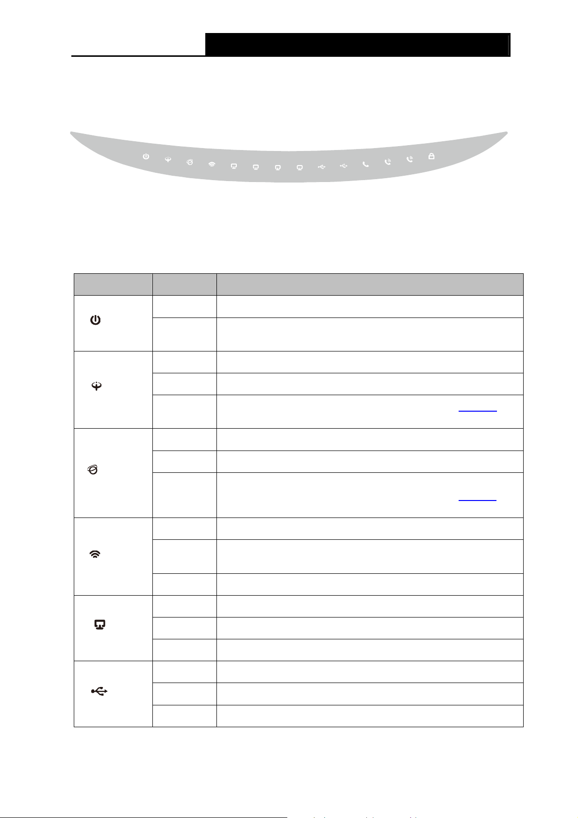
1.3.1 The Front Panel
Figure 1-1
The Router’s LEDs are located on the front panel (View from left to right). They indicate the
device’s working status. For details, please refer to LED Explanation.
LED Explanation:
Name Status Indication
On The modem router is powered on.
(Power)
Off
The modem router is off. Please ensure that the power adapter is
connected correctly.
(ADSL)
(Internet)
(WLAN)
(LAN1-4)
On ADSL line is synchronized and ready to use.
Flash The ADSL negotiation is in progress.
Off
On The network is available with a successful Internet connection.
Flash There is data being transmitted or received via the Internet.
Off
On Wireless is enabled but no data is being transmitted.
Flash
Off Wireless function is disabled.
On There is a device connected to this LAN port.
Flash The modem router is sending or receiving data over this LAN port.
ADSL synchronization fails. Please refer to Note 1
troubleshooting.
There is no successful Internet connection or the modem router is
operating in Bridge mode. Please refer to Note 2
troubleshooting.
The modem router is sending or receiving data over the wireless
network.
for
for
(USB)
Off There is no device connected to this LAN port.
On A storage device or printer has connected to the USB port.
Flash The modem router is sending or receiving data over this USB port.
Off No storage device or printer is plugged into the USB port.
4
Page 14

TD-VG3631 300Mbps Wireless N VoIP ADSL2+ Modem Router User Guide
On A valid PSTN connection.
(Line)
(Phone1-2)
(WPS)
Note:
)
1. If the ADSL LED is off, please check your Internet connection first. Refer to 2.3 Connecting
the Modem Router for more information about how to make Internet connection correctly. If
you have already made a right connection, please contact your ISP to make sure if your
Internet service is available now.
Flash
Off PSTN connection fails.
On The phone is off hook.
Flash The phone is ringing.
Off The phone is on hook.
On
Slow Flash
Quick Flash
Incoming calls and outgoing calls are transmitted trough PSTN
line.
A wireless device has been successfully added to the network by
WPS function.
WPS handshaking is in process and will continue for about 2
minutes. Please press the WPS button on other wireless devices
that you want to add to the network while the LED is flashing.
A wireless device has failed to be added to the network by WPS
function. Please refer to 4.6.2 WPS Settings
for more information.
2. If the Internet LED is off, please check your ADSL LED first. If your ADSL LED is also off,
please refer to Note 1
configuration. You may need to check this part of information with your ISP and make sure
everything have been input correctly.
. If your ADSL LED is GREEN ON, please check your Internet
5
Page 15
TD-VG3631 300Mbps Wireless N VoIP ADSL2+ Modem Router User Guide
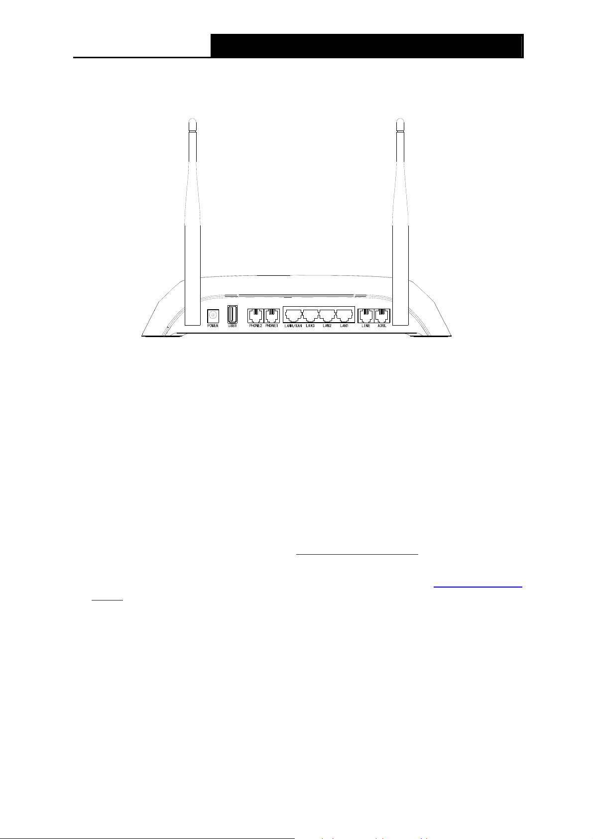
1.3.2 The Back Panel
The Router's ports, where the cables are connected, and RESET button are located on the front.
Figure 1-2
¾ POWER: The Power plug is where you will connect the power adapter.
¾ USB1/USB2: The USB port connects to a USB storage device or a USB printer.
¾ PHONE2/PHONE1:The phone port connects to a phone set.
Note:
)
Port PHONE 2 is designed to ensure power failure tolerance. The analog telephone connected to
it can still make and receive PSTN calls even when the device is powered off.
¾ LAN1, LAN2, LAN3, LAN4/WAN: Through these ports, you can connect the Router to your
PC or the other Ethernet network devices. Enable EWAN function and you will be able to
connect to Cable/FTTH/VDSL/ADSL device.
¾ LINE: Connect this port to PSTN phone cable. Or you can connect them by an external
separate splitter. For details, please refer to 2.3 Connecting the Router
¾ ADSL: Through the port, you can connect the Modem Router with the telephone. Or you can
connect them by an external separate splitter. For details, please refer to 2.3 Connecting the
Router.
¾ Antennas: Used for wireless operation and data transmit.
¾ RESET: There are two ways to reset the Router's factory defaults.
.
Method one: With the Router powered on, use a pin to press and hold the Reset button for at
least 5 seconds. And the Router will reboot to its factory default settings.
Method two: Restore the default setting from “Maintenance-SysRestart” of the Router's
Web-based Utility.
Ports and buttons located on the side
6
Page 16
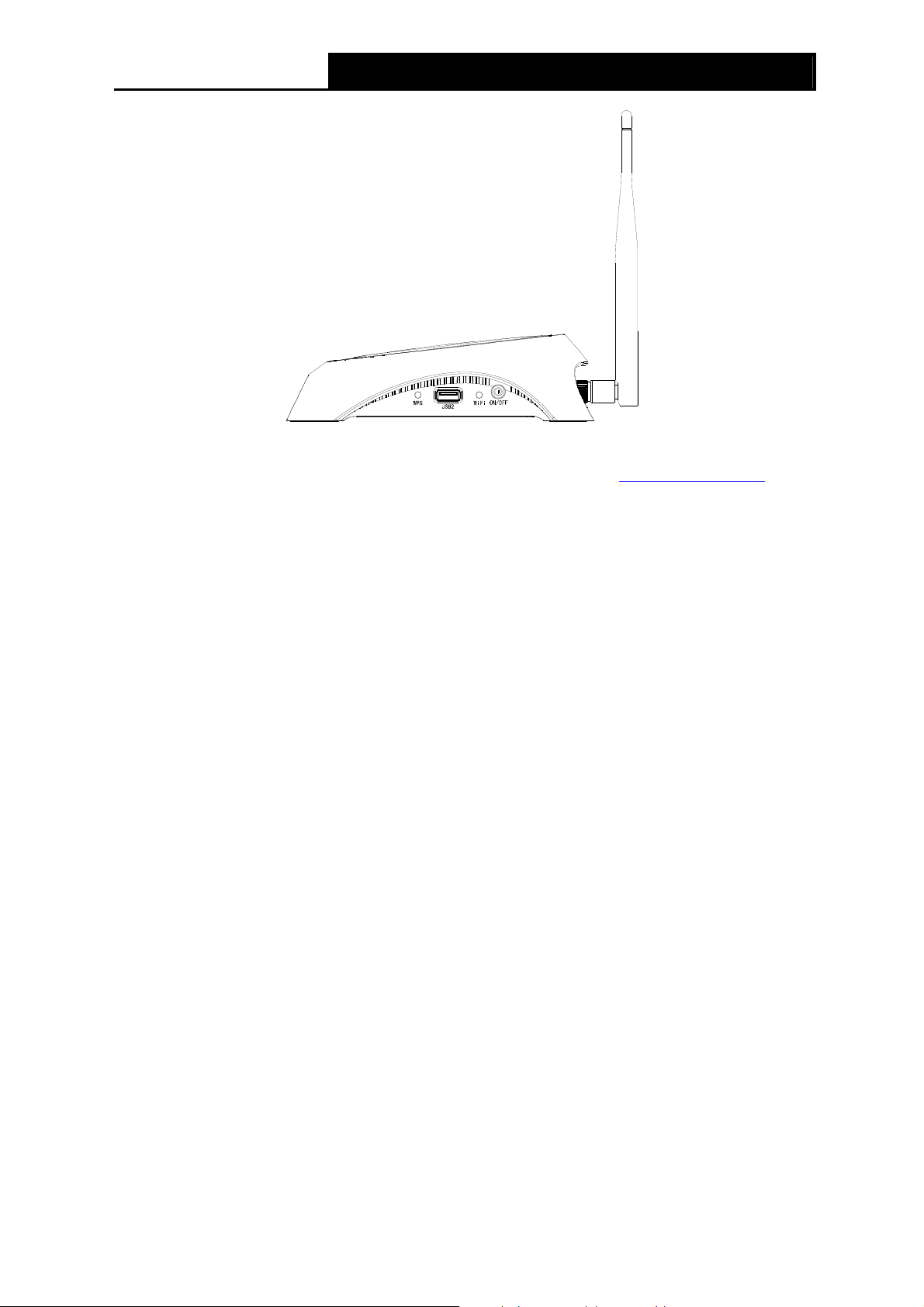
TD-VG3631 300Mbps Wireless N VoIP ADSL2+ Modem Router User Guide
Figure 1-3
¾ WPS: The switch for the WPS function. For details, please refer to 4.6.2 WPS Settings
¾ WiFi: The switch for the WiFi function.
¾ ON/OFF: The switch for the power.
.
7
Page 17

TD-VG3631 300Mbps Wireless N VoIP ADSL2+ Modem Router User Guide
Chapter 2. Connecting the Modem Router
2.1 System Requirements
¾ Broadband Internet Access Service (DSL/Cable/Ethernet).
¾ PCs with a working Ethernet Adapter and an Ethernet cable with RJ45 connectors.
¾ TCP/IP protocol on each PC.
¾ Web browser, such as Microsoft Internet Explorer, Mozilla Firefox or Apple Safari.
2.2 Installation Environment Requirements
¾ The Product should not be located where it will be exposed to moisture or excessive heat.
¾ Place the Router in a location where it can be connected to the various devices as well as to a
power source.
¾ Make sure the cables and power cord are safely placed out of the way so they do not create a
tripping hazard.
¾ The Router can be placed on a shelf or desktop.
¾ Keep away from the strong electromagnetic radiation and the device of electromagnetic
sensitive.
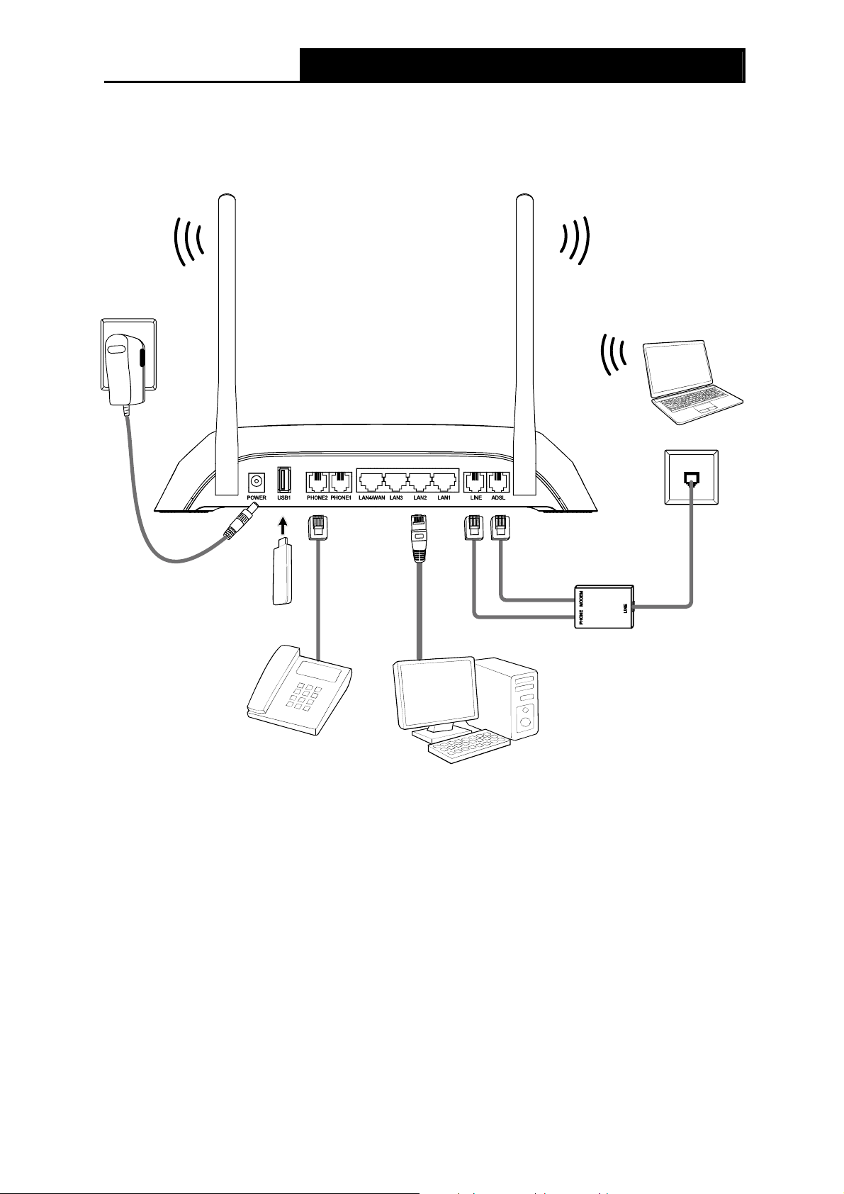
2.3 Connecting the Modem Router
Before installing the device, please make sure your broadband service provided by your ISP is
available. If there is any problem, please contact your ISP. Before cable connection, cut off the
power supply and keep your hands dry. You can follow the steps below to install it.
Step 1: Connect the ADSL Line. You can use a separate splitter. External splitter can divide the
data and voice, and then you can access the Internet and make calls at the same time.
The external splitter has three ports:
• LINE: Connect to the wall jack
• PHONE: Connect to the LINE port of the Modem Router
• MODEM: Connect to the ADSL port of the Modem Router
Step 2: Connect the Ethernet cable. Attach one end of a network cable to your computer’s
Ethernet port or a regular hub/switch port, and the other end to the LAN port on the
Modem Router.
Step 3: Connect your telephone to the Port labeled “PHONE 1/2” on the Modem Router with a
telephone line.
Step 4: Connect your USB device to the USB port labeled “USB 1/2” on the Modem Router.
If you want to share files or use the USB Voice Mail function, please plug an external USB hard
drive/USB flash disk into the USB port. To use the printer function, please connect a USB printer
to the USB port.
To use USB Voice Mail function, please make sure the free space of the plugged external USB
hard drive/USB flash disk is more than 4MB.
8
Page 18
TD-VG3631 300Mbps Wireless N VoIP ADSL2+ Modem Router User Guide
Step 5: Power on the computers and LAN devices.
Step 6: Attach the power adapter. Connect the power adapter to the power connector on the rear
of the device and plug in the adapter to an electrical outlet or power extension. The
electrical outlet shall be installed near the device and shall be easily accessible.
Figure 2-1
9
Page 19
TD-VG3631 300Mbps Wireless N VoIP ADSL2+ Modem Router User Guide
Chapter 3. Quick Installation Guide
3.1 Configuring the PC
After you directly connect your PC to the Modem Router or connect your adapter to a Hub/Switch
which has connected to the Modem Router, you need to configure your PC’s IP address. Follow
the steps below to configure it.
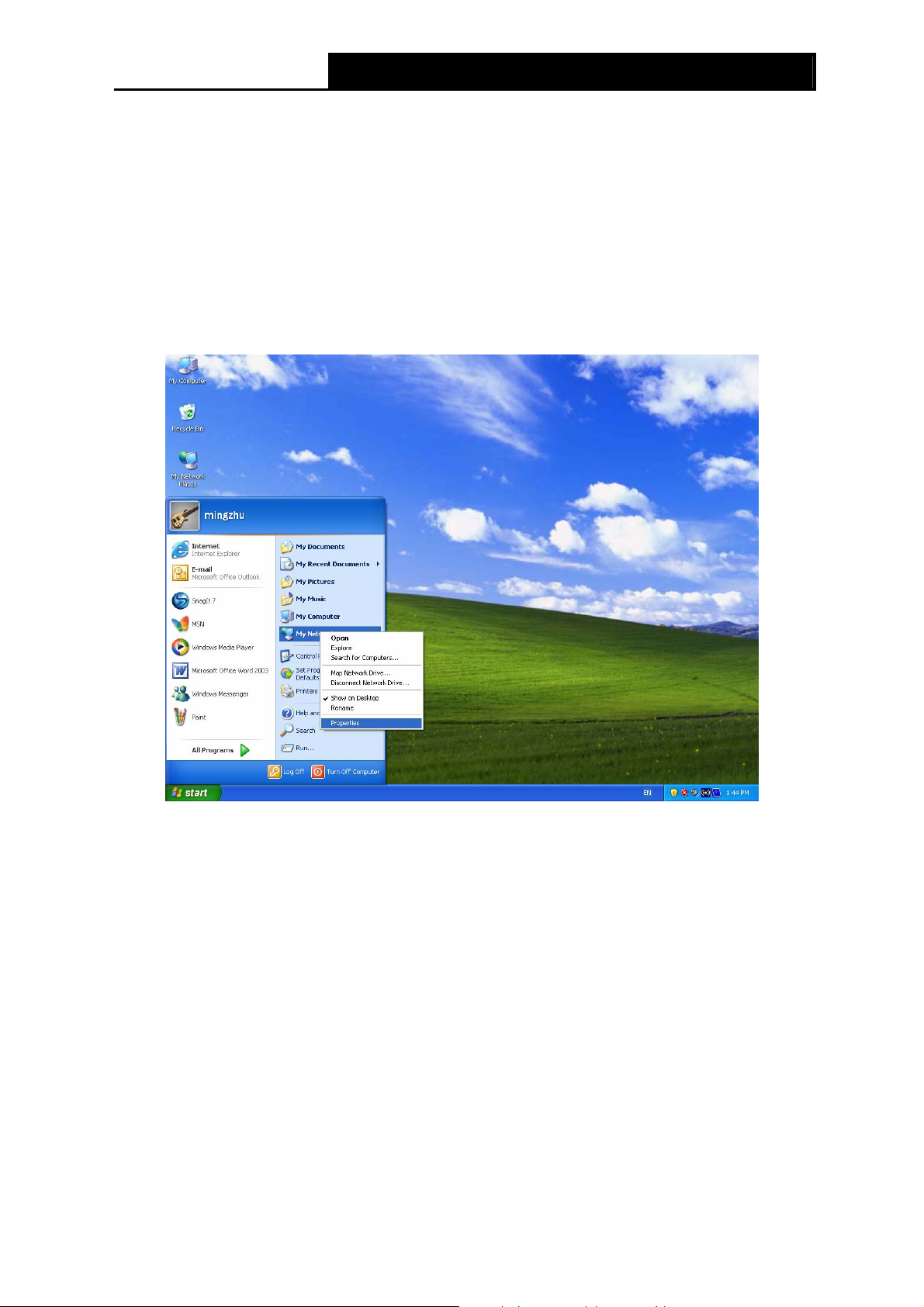
Step 1: Click the Start menu on your desktop, right click My Network Places, and then select
Properties (shown in Figure 3-1).
Figure 3-1
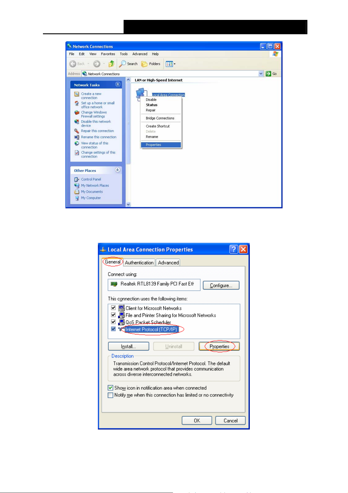
Step 2: Right click Local Area Connection (LAN), and then select Properties.
10
Page 20
TD-VG3631 300Mbps Wireless N VoIP ADSL2+ Modem Router User Guide
Figure 3-2
Step 3: Select General tab, highlight Internet Protocol (TCP/IP), and then click the Properties
button.
Figure 3-3
11
Page 21
TD-VG3631 300Mbps Wireless N VoIP ADSL2+ Modem Router User Guide
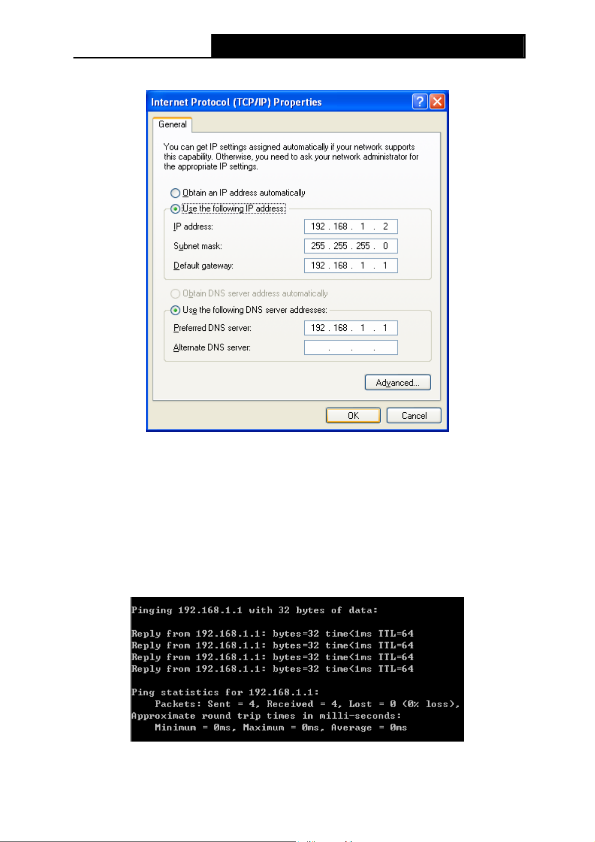
Step 4: Configure the IP address as Figure 3-4 shows. After that, click OK.
Figure 3-4
Note:
)
You can configure the PC to get an IP address automatically, select “Obtain an IP address
automatically” and “Obtain DNS server address automatically” in the screen above.
Now, you can run the Ping command in the command prompt to verify the network connection.
Please click the Start menu on your desktop, select run tab, type cmd or command in the field
and press Enter. Type ping 192.168.1.1 on the next screen, and then press Enter.
If the result displayed is similar to the screen below, the connection between your PC and the
Modem Router has been established.
Figure 3-5
12
Page 22
TD-VG3631 300Mbps Wireless N VoIP ADSL2+ Modem Router User Guide
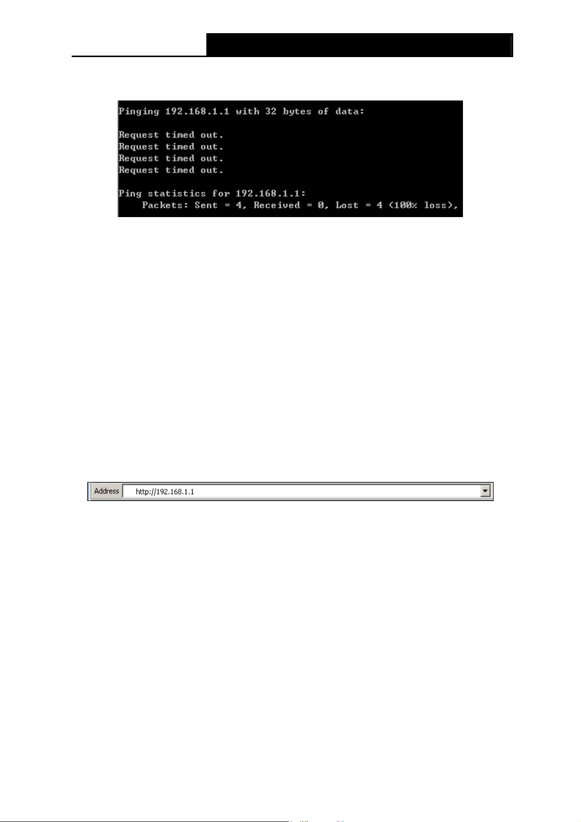
If the result displayed is similar to the screen shown below, it means that your PC has not
connected to the Modem Router.
Figure 3-6
You can check it following the steps below:
1) Is the connection between your PC and the Modem Router correct?
The LEDs of LAN port which you link to the device and the LEDs on your PC's adapter should
be lit.
2) Is the TCP/IP configuration for your PC correct?
If the Router's IP address is 192.168.1.1, your PC's IP address must be within the range of
192.168.1.2 ~ 192.168.1.254.
3.2 Quick Installation Guide
With a Web-based utility, it is easy to configure and manage the TD-VG3631 300Mbps Wireless N
VoIP ADSL2+ Modem Router. The Web-based utility can be used on any Windows, Macintosh or
UNIX OS with a Web browser, such as Microsoft Internet Explorer, Mozilla Firefox or Apple Safari.
1. To access the configuration utility, open a web-browser and type the default address
http://192.168.1.1 in the address field of the browser.
Figure 3-7
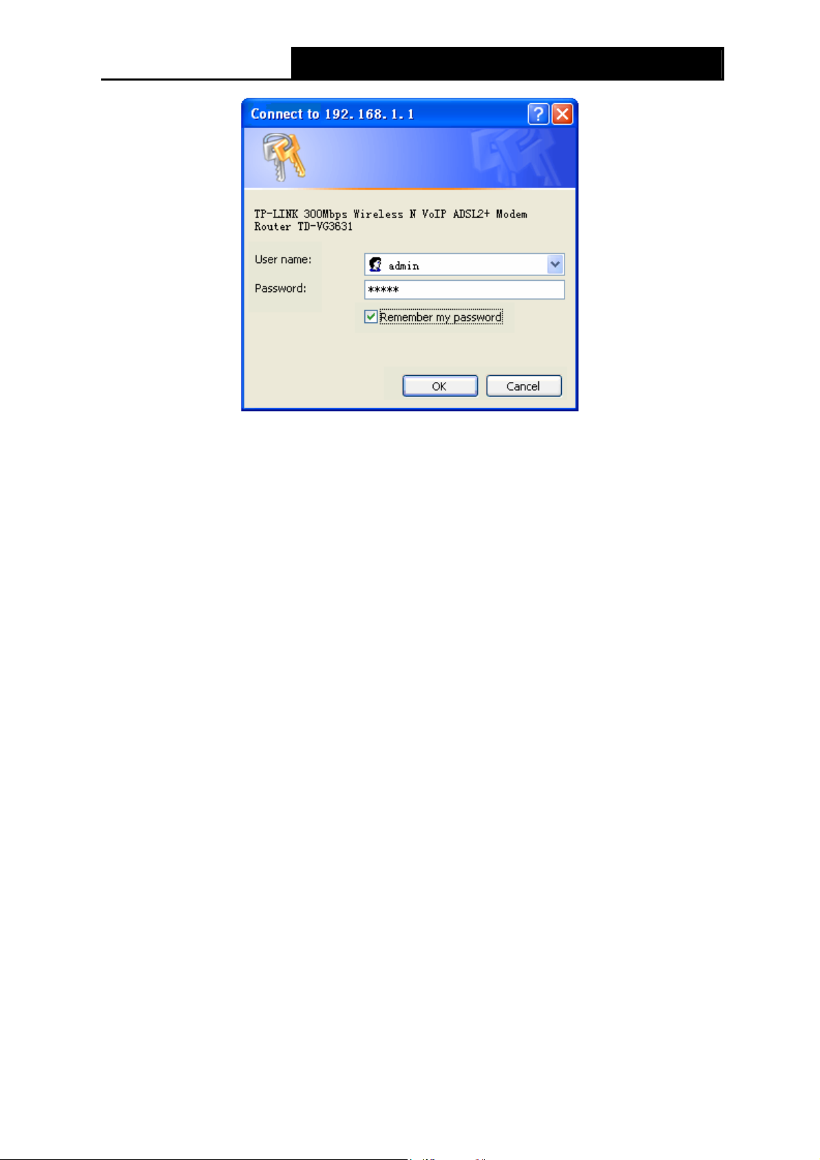
After a moment, a login window will appear, similar to the Figure 3-8. Enter admin for the
User Name and Password, both in lower case letters. Then click the OK button or press the
Enter key.
13
Page 23
TD-VG3631 300Mbps Wireless N VoIP ADSL2+ Modem Router User Guide
Figure 3-8
Note:
)
1) Do not mix up the user name and password with your ADSL account user name and password
which are needed for PPP connections.
2) If the above screen does not pop up, it means that your Web-browser has been set to a proxy.
Go to Tools menu→Network→LAN Settings, in the screen that appears, cancel the Using
Proxy checkbox, and click OK to finish it.
2. After your successful login, you will see the Login screen as shown in Figure 3-9. Click Quick
Setup menu to access Quick Setup Wizard.
14
Page 24
TD-VG3631 300Mbps Wireless N VoIP ADSL2+ Modem Router User Guide
Figure 3-9
3. Change the VPI or VCI values which are used to define a unique path for your connection. If
you have been given specific settings for this to configuration, type in the correct
values assigned by your ISP. Click Next.
15
Page 25
TD-VG3631 300Mbps Wireless N VoIP ADSL2+ Modem Router User Guide
Figure 3-10
4. Here we select PPPoE WAN Link Type for example, enter the Username, Password and
Confirm Password given by your ISP, and then click Next.
Figure 3-11
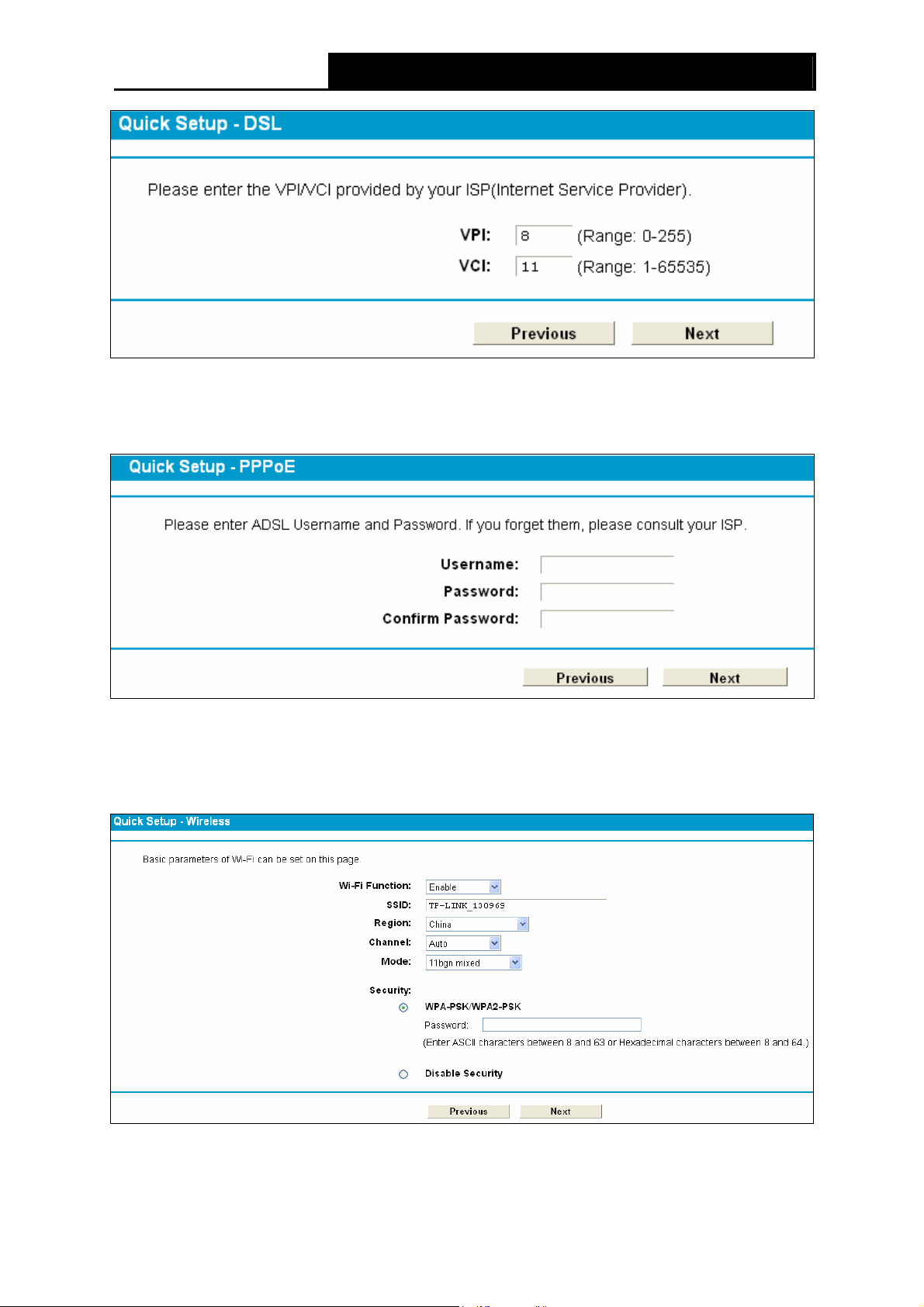
5. On the Wireless screen, we use the default SSID, select Region and Mode. Set a Password
or select Disable Security(Disable Security is not recommended.), and then click Next to
continue.
Figure 3-12
16
Page 26
TD-VG3631 300Mbps Wireless N VoIP ADSL2+ Modem Router User Guide
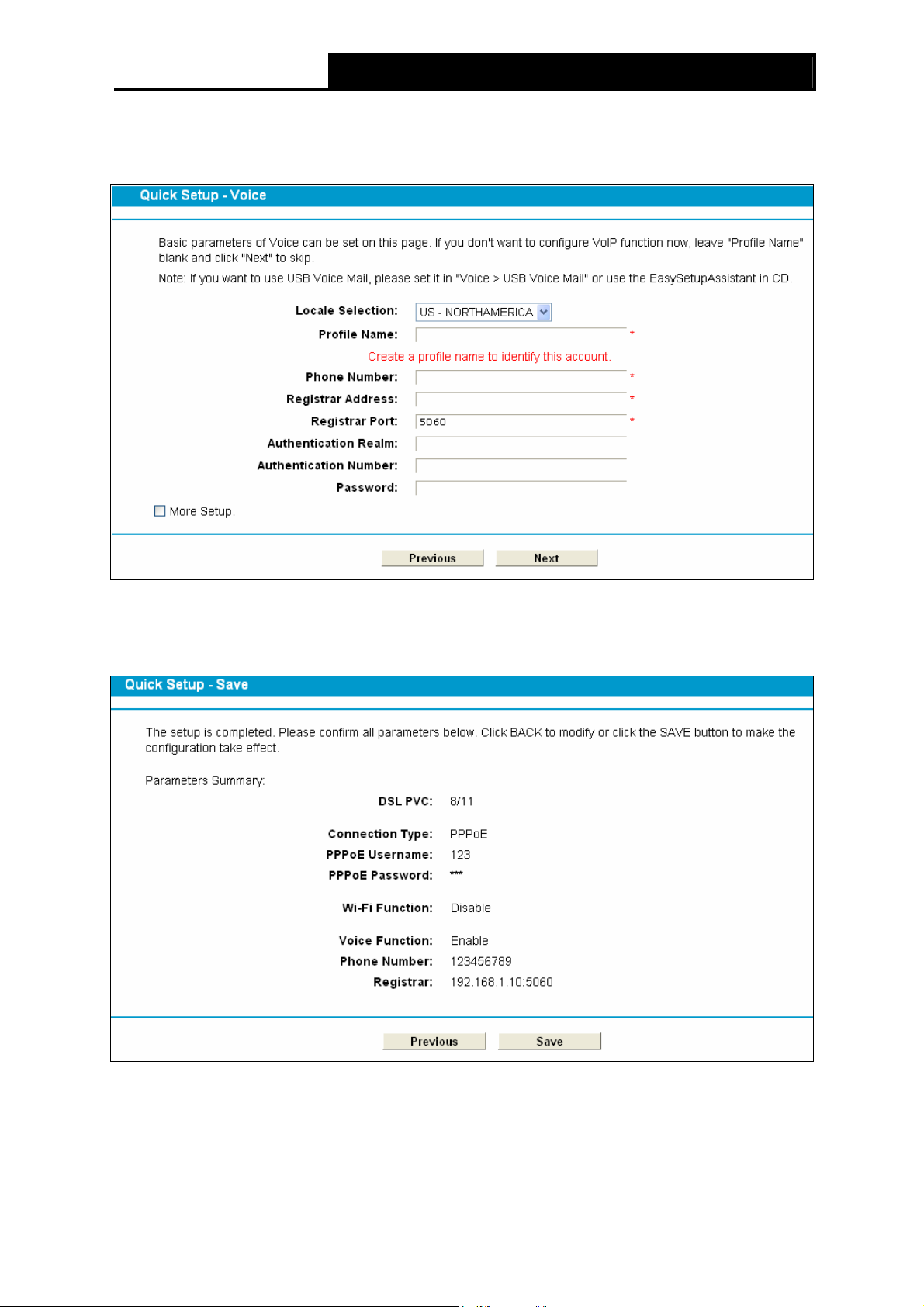
6. Basic parameters of Voice can be set on the Voice screen. Please enter a profile name to
identify this account and other parameters provided by your ISP. If you don’t want to configure
VoIP function now, leave "Profile Name" blank and click Next to skip.
Figure 3-13
7. On this page, please confirm all parameters. Click Previous to modify or click the Save
button to make the configuration take effect.
Figure 3-14
8. You will see the Complete screen below, click Finish to complete these settings.
17
Page 27
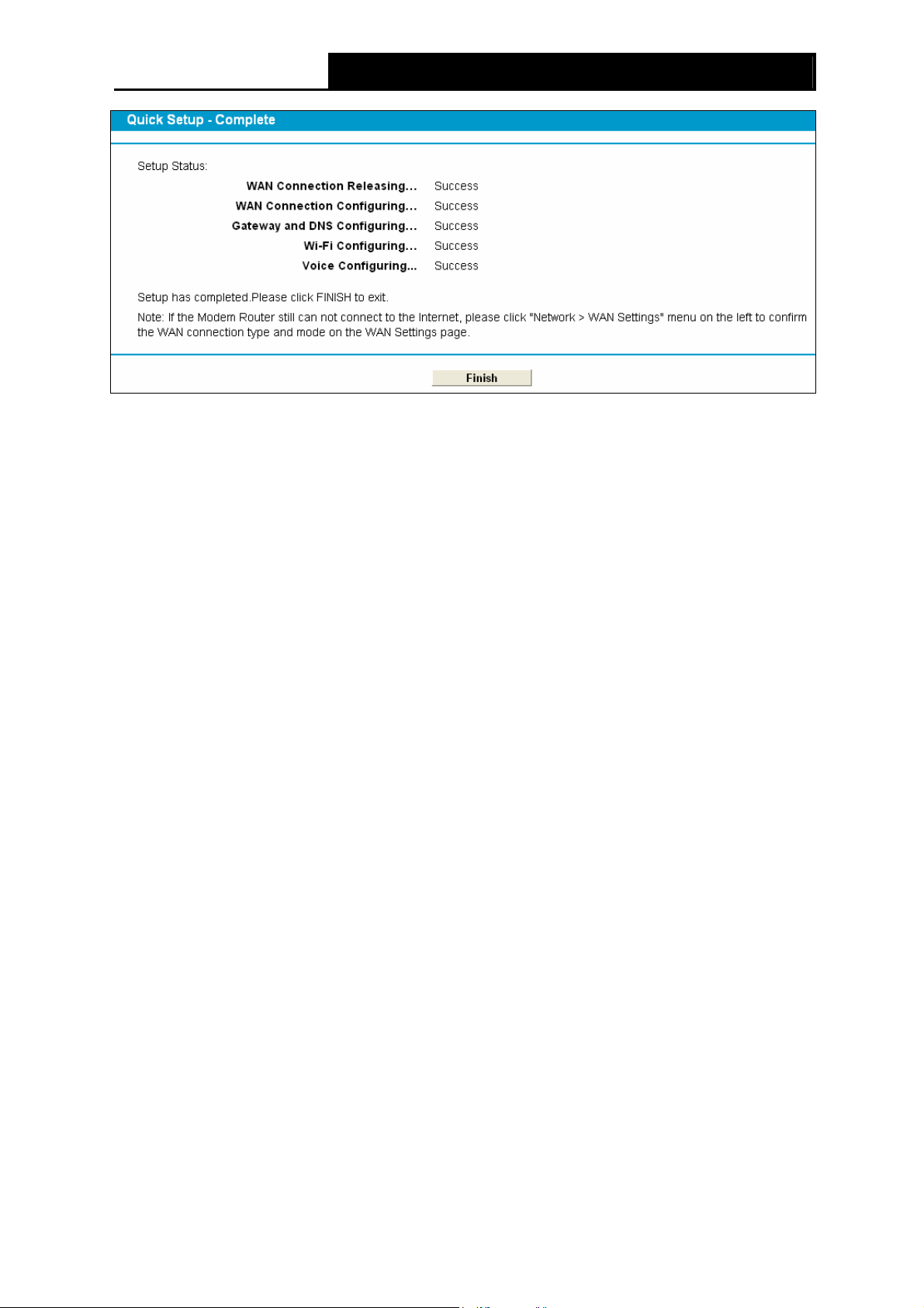
TD-VG3631 300Mbps Wireless N VoIP ADSL2+ Modem Router User Guide
Figure 3-15
18
Page 28
TD-VG3631 300Mbps Wireless N VoIP ADSL2+ Modem Router User Guide
Chapter 4. Configuring the Modem Router
This chapter will show each Web page's key function and the configuration way.
4.1 Login
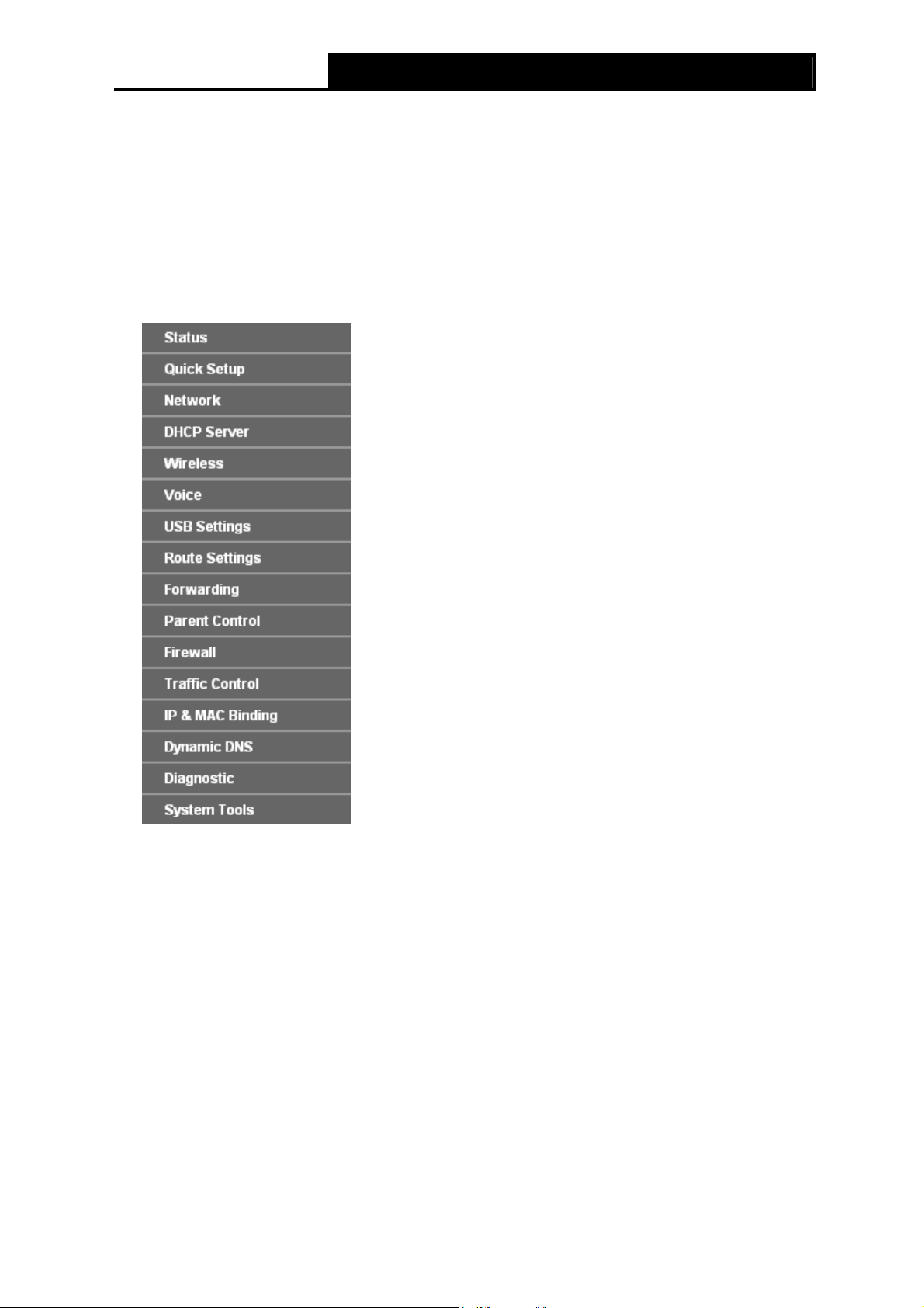
After your successful login, you will see the fifteen main menus on the left of the Web-based utility.
On the right, there are the corresponding explanations and instructions.
The detailed explanations for each Web page’s key function are listed below.
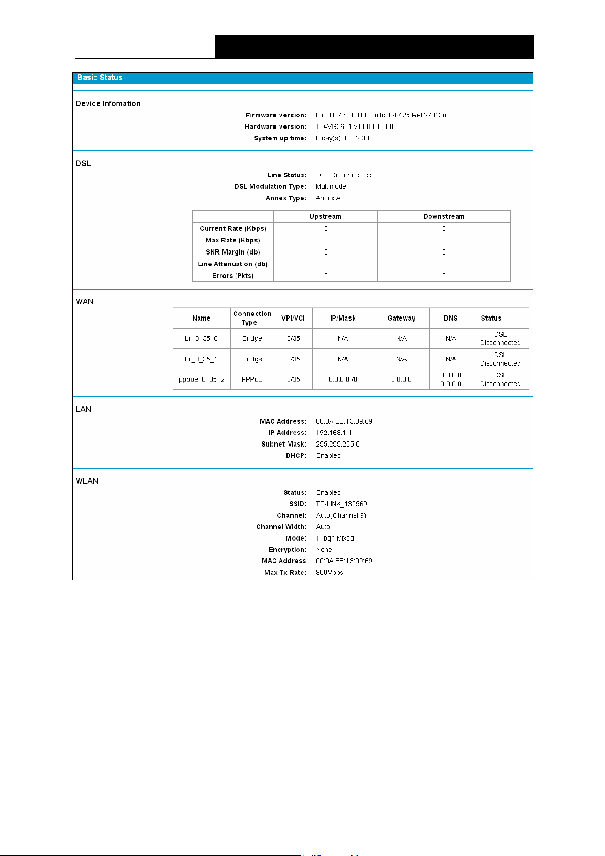
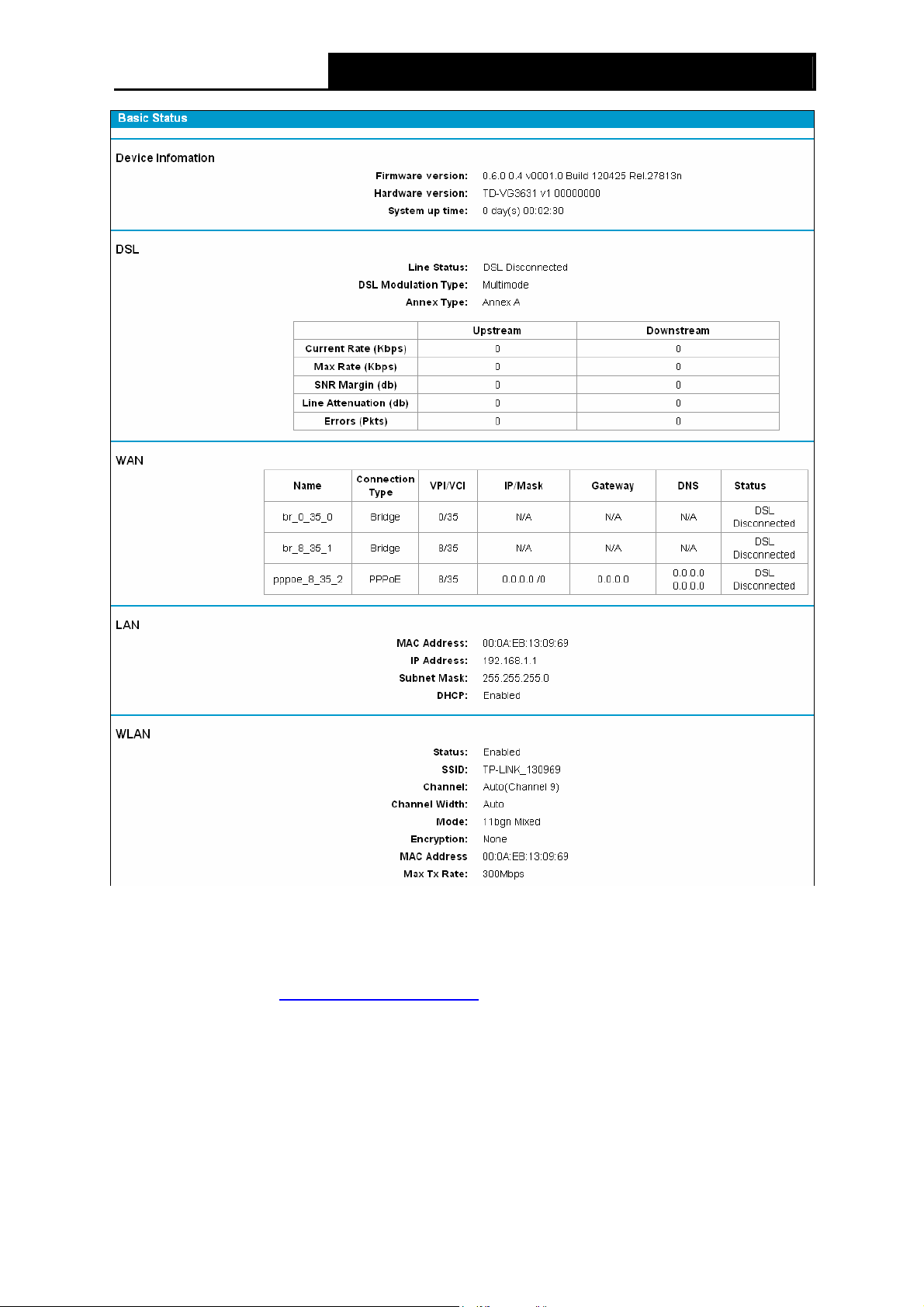
4.2 Status
Choose “Status”, you can see the corresponding information about Device Information, DSL,
WAN, LAN WLAN and Voice.
19
Page 29
TD-VG3631 300Mbps Wireless N VoIP ADSL2+ Modem Router User Guide
Figure 4-1
4.3 Quick Setup
Please refer to Section 3.2 Quick Installation Guide.
4.4 Network
Choose “Network”, there are many submenus under the main menu. Click any one of them, and
you will be able to configure the corresponding function.
20
Page 30
TD-VG3631 300Mbps Wireless N VoIP ADSL2+ Modem Router User Guide
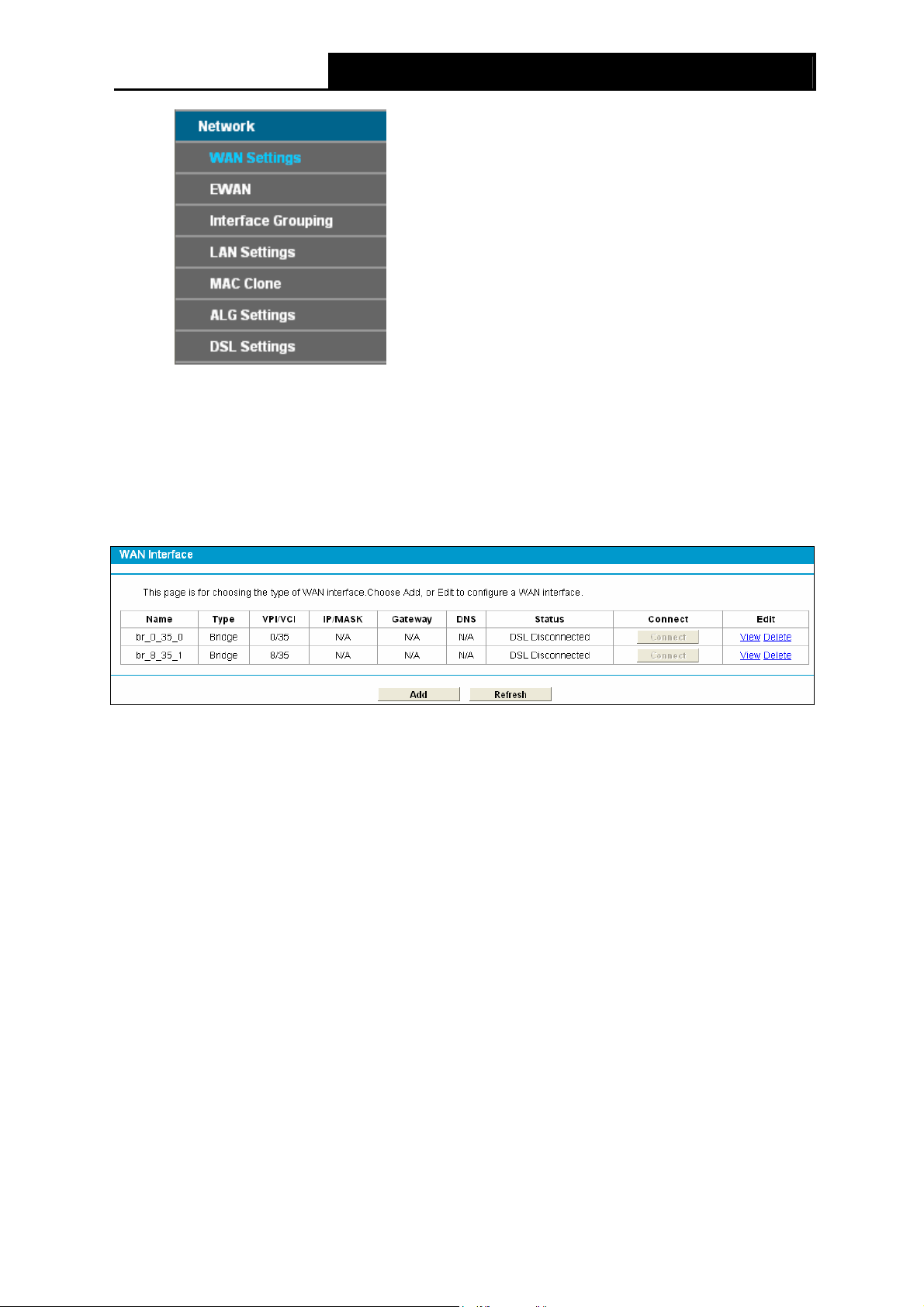
4.4.1 WAN Settings
Choose “Network”Æ“WAN Settings”, and you will see the WAN Port Information Table in the
screen similar to Figure 4-2, which describes the WAN port settings and the relevant manipulation
to each interface. There are five different configurations for the connection types, which are Static
IP, Dynamic IP, PPPoE, IPoA, and Bridge. You can select the corresponding types according to
your needs.
Figure 4-2
Click Add to add a new entry, you can configure the parameters for ATM and WAN Service in the
next screen (shown in Figure 4-3).
21
Page 31

TD-VG3631 300Mbps Wireless N VoIP ADSL2+ Modem Router User Guide
Figure 4-3
4.4.1.1 Static IP
Select this option if your ISP provides static IP information to you. You should set static IP address,
IP subnet mask, and gateway address in the screen below.
22
Page 32

TD-VG3631 300Mbps Wireless N VoIP ADSL2+ Modem Router User Guide
Figure 4-4
ATM Configuration:
¾ VPI (0~255): Identifies the virtual path between endpoints in an ATM network. The valid range
is from 0 to 255. Please input the value provided by your ISP.
¾ VCI (1~65535): Identifies the virtual channel endpoints in an ATM network. The valid range is
from 1 to 65535 (1 to 31 is reserved for well-known protocols). Please input the value
provided by your ISP.
Click Advanced, advanced selections of ATM Configuration can be shown.
¾ Encapsulation Mode: Select the encapsulation mode for the Static IP Address. Here you
can leave it default.
¾ ATM Qos Type: Select ATM Qos Type provided by ISP, and the type is UBR by default.
WAN Service Setup:
¾ IP Address: Enter the IP address in dotted-decimal notation provided by your ISP.
¾ Subnet Mask: Enter the subnet Mask in dotted-decimal notation provided by your ISP,
usually is 255.255.255.0.
¾ Default Gateway (Optional): Enter the gateway IP address in dotted-decimal notation
provided by your ISP.
23
Page 33

TD-VG3631 300Mbps Wireless N VoIP ADSL2+ Modem Router User Guide
¾ DNS Server/ Secondary DNS Server: Here you can set DNS Server (at least one) manually.
The Route will use this DNS Server for priority.
¾ Default Gateway: select a WAN Interface from the drop-down list as the IPv4 default
gateway.
¾ MTU (bytes): Maximum Transmission Unit Size. Check this box then you can change the MTU
size. The default MTU value is 1500 Bytes. It is not recommended that you change the default
value unless required by your ISP.
¾ Enable NAT: This technology translates the IP addresses of a local area network to a different
IP address for the Internet. If this Modem Router is hosting your network’s connection to the
Internet, please select the check box. If another Router exists in your network, you don’t need
to select the option.
¾ Enable Fullcone NAT: It is a type of NAT, if not enabled, the default NAT will act.
¾ Enable SPI Firewall: A SPI firewall enhances network’s security. Select the option to use a
firewall, or else without a firewall.
¾ Enable IGMP Proxy: IGMP (Internet Group Management Protocol) is used to manage
multicasting on TCP/IP networks. Some ISPs use IGMP to perform remote configuration for
client devices, such as the Modem Router. The default value is disabled, and if you are not
sure, please contact your ISP or just leave it.
Click the Save button to save the settings.
4.4.1.2 Dynamic IP
Select this option, the Modem Router will be able to obtain IP network information dynamically
from a DHCP server provided by your ISP.
24
Page 34

TD-VG3631 300Mbps Wireless N VoIP ADSL2+ Modem Router User Guide
Figure 4-5
Click Advanced, advanced selections for WAN Service Setup can be shown.
¾ MTU (bytes): Maximum Transmission Unit Size. Check this box then you can change the MTU
size. The default MTU value is 1500 Bytes. It is not recommended that you change the default
value unless required by your ISP.
¾ Enable NAT: This technology translates the IP addresses of a local area network to a different
IP address for the Internet. If this Modem Router is hosting your network’s connection to the
Internet, please select the check box. If another Router exists in your network, you don’t need
to select the option.
¾ Enable Fullcone NAT: It is a type of NAT, if not enabled, the default NAT will act.
¾ Enable SPI Firewall: A SPI firewall enhances network’s security. Select the option to use a
firewall, or else without a firewall.
¾ Enable IGMP Proxy: IGMP (Internet Group Management Protocol) is used to manage
multicasting on TCP/IP networks. Some ISPs use IGMP to perform remote configuration for
client devices, such as the Modem Router. The default value is enabled, and if you are not
sure, please contact your ISP or just leave it.
¾ Get IP Unicast: This is disabled by default. The minority of DHCP Server of ISP will not
support to enable this. When the Route is connected right but IP cannot get, you can select this
box.
25
Page 35

TD-VG3631 300Mbps Wireless N VoIP ADSL2+ Modem Router User Guide
¾ Primary DNS Server/ Secondary DNS Server: Choose “Set DNS Server manually”, you can
set DNS Server (at least one) manually here. The Route will use this DNS Server for priority.
Click the Save button to save the settings.
4.4.1.3 PPPoE
If your ISP provides a PPPoE connection and you need to use an ATM Interface, choose PPPoE
in the drop-down list, and then the screen will be displayed as below.
Figure 4-6
¾ PPP Username/Password/Confirm Password: Enter the User Name, Password and
Confirm Password provided by your ISP. These fields are case-sensitive.
26
Page 36

TD-VG3631 300Mbps Wireless N VoIP ADSL2+ Modem Router User Guide
¾ Authentication Method: Select the Authentication Method from the drop-down list, the
default method is AUTO_AUTH, and you can leave it as a default setting.
¾ Choose the right connection type according to your needs: For PPPoE connection, you
can select Connect on demand or Connect automatically or Connect manually. Connect
on demand is dependent on the traffic. If there is no traffic (or Idle) for a pre-specified period
of time), the connection will tear down automatically. And once there is traffic send or receive,
the connection will be automatically on.
Click Advanced, advanced selections for WAN Service Setup can be shown.
¾ Service Name/Server Name: Enter the Service Name and Server Name if it was provided by
your ISP. You can leave them blank, if the ISP doesn’t provide them.
4.4.1.4 PPPoA
If your ISP provides a PPPoA connection and you need to use an ATM Interface, choose PPPoA
in the drop-down list, and then the screen will be displayed as below.
The configuration is similar to PPPoE. Please refer to the section 4.4.14 PPPoE
part.
to configure this
27
Page 37

TD-VG3631 300Mbps Wireless N VoIP ADSL2+ Modem Router User Guide
Figure 4-7
4.4.1.5 IPoA
If your ISP provides an IPoA connection, select IPoA option for the WAN service type on the
screen.
28
Page 38

TD-VG3631 300Mbps Wireless N VoIP ADSL2+ Modem Router User Guide
Figure 4-8
¾ IP Address/Subnet Mask: Enter the IP Address and Subnet Mask provided by ISP. If you
forget, you can ask your ISP.
¾ DNS Server/Secondary DNS Server: Type in your preferred DNS server.
¾ Default Gateway: select a WAN Interface from the drop-down list as the IPv4 default
gateway.
4.4.1.6 Bridge
If you select this type of connection, the modem can be configured to act as a bridging device
between your LAN and your ISP. Bridges are devices that enable two or more networks to
communicate as if they are two segments of the same physical LAN.
29
Page 39

TD-VG3631 300Mbps Wireless N VoIP ADSL2+ Modem Router User Guide
Figure 4-9
Note:
)
After you finish the Internet configuration, please click Save to make the settings take effect.
4.4.2 EWAN
Choose “Network”Æ“EWAN”, and you will see the Ethernet WAN Interface screen similar to
Figure 4-10. There are three different configurations for the connection types, which are Dynamic
IP, Static IP and PPPoE. You can select the corresponding types according to your needs.
Note:
)
1) EWAN and DSL interface can not be used concurrently. If the EWAN Interface had configured,
you cannot configure any other WAN service over the DSL Interface until the EWAN Interface
is deleted.
2) If EWAN function is be enabled, LAN4/WAN port of the Modem Router changes to be WAN
port which can be connected to the cable, VDSL or Fiber modem.
30
Page 40

TD-VG3631 300Mbps Wireless N VoIP ADSL2+ Modem Router User Guide
Figure 4-10
4.4.2.1 Dynamic IP
Select this option, the Modem Router will be able to obtain IP network information dynamically
from a DHCP server provided by your ISP (as shown Figure 4-10). The next configuration is
similar to Dynamic IP over ATM interface (see section 4.4.1.2 Dynamic IP
)
4.4.2.2 Static IP
Select this option if your ISP provides static IP information to you and you want to use an Ethernet
Interface. You should set static IP address, IP subnet mask, gateway address, DNS Server and
Secondary DNS Server in the screen below. The next configuration is similar to Static IP for WAN
Settings (see section 4.4.1.1 Static IP
)
31
Page 41

TD-VG3631 300Mbps Wireless N VoIP ADSL2+ Modem Router User Guide
Figure 4-11
4.4.2.3 PPPoE
If your ISP provides a PPPoE connection and you need to use an Ethernet Interface, select
PPPoE option for the WAN service type on the screen. The following configuration is similar to
PPPoE over ATM interface (see section 4.4.1.3 PPPoE
).
32
Page 42

TD-VG3631 300Mbps Wireless N VoIP ADSL2+ Modem Router User Guide
Figure 4-12
4.4.3 Interface Grouping
Choose “Network”Æ“Interface Grouping”, you can view all the current groups on this page
(shown in Figure 4-13).
Figure 4-13
33
Page 43

TD-VG3631 300Mbps Wireless N VoIP ADSL2+ Modem Router User Guide
¾ VLAN: Enable or disable this function. Virtual LAN (VLAN) is a group of devices on one or
more LANs that are configured so that they can communicate as if they were attached to the
same LAN, when in fact they are located on a number of different LAN segments. Because
VLANs are based on logical instead of physical connections, it is very flexible for user/host
management, bandwidth allocation and resource optimization. If you want to active this
function, this function must be enabled.
Note:
)
It is not allowed to disable the VLAN with Ethernet Connection enabled.
To support this feature, you must create mapping groups with appropriate LAN and WAN
interfaces using the Add button. The Remove button will remove the grouping and add the
ungrouped interfaces to the Default group. Only the default group has IP interface.
Click the Add button. You can add a new interface group in the next screen. For example, you
want LAN1 and LAN3 to be a group called Group 1 over br_0_35_0 WAN interface, you can refer
to the following figure.
Figure 4-14
Click Save to make the entry effective immediately
4.4.4 LAN Settings
Choose “Network”Æ“LAN Settings” menu, and you will see the LAN screen (shown in Figure
4-15). Please configure the parameters for LAN ports according to the descriptions below.
34
Page 44

TD-VG3631 300Mbps Wireless N VoIP ADSL2+ Modem Router User Guide
Figure 4-15
¾ IP Address: You can configure the Modem Router’s IP Address and Subnet Mask for LAN
Interface.
• IP Address: Enter the Modem Router’s local IP Address, then you can access to the
Web-based Utility via the IP Address, the default value is 192.168.1.1.
• Subnet Mask: Enter the Modem Router’s Subnet Mask, the default value is
255.255.255.0.
¾ Enable IGMP Snooping: If you select the option, please choose the IGMP Mode: Standard
Mode or Blocking Mode.
¾ Enable Second IP: You can configure the Modem Router’s second IP Address and Subnet
Mask for LAN Interface through which you can also access to the Web-based Utility as the
default IP Address and Subnet Mask.
¾ DHCP Server: These settings allow you to configure the Modem Router‘s Dynamic Host
Configuration Protocol (DHCP) server function. The DHCP server is enabled by default for the
Modem Router’s Ethernet LAN interface. DHCP service will supply IP settings to computers
which are configured to automatically obtain IP settings that are connected to the Modem
Router though the Ethernet port. When the Modem Router is set for DHCP, it becomes the
default gateway for DHCP client connected to it. Keep in mind that if you change the IP
address of the Modem Router, you must change the range of IP addresses in the pool used
for DHCP on the LAN.
• Start IP Address: Enter a value for the DHCP server to start with when issuing IP
addresses. Because the default IP address for the Modem Router is 192.168.1.1, the
default Start IP Address is 192.168.1.100, and the Start IP Address must be 192.168.1.100
or greater, but smaller than 192.168.1.254.
• End IP Address: Enter a value for the DHCP server to end with when issuing IP
addresses. The End IP Address must be smaller than 192.168.1.254. The default End IP
Address is 192.168.1.254.
35
Page 45

TD-VG3631 300Mbps Wireless N VoIP ADSL2+ Modem Router User Guide
• Leased Time: The Leased Time is the amount of time in which a network user will be
allowed connection to the Modem Router with their current dynamic IP address. Enter the
amount of time, in hours, then the user will be “leased” this dynamic IP address. After the
dynamic IP address has expired, the user will be automatically assigned a new dynamic IP
address. The default is 1440 minutes.
The detailed configuration about DHCP server, please refer to section 4.5 DHCP Server
.
4.4.5 MAC Clone
Choose menu “Advanced Setup”Æ“MAC Clone”, you can configure the MAC address of the
WAN Interface as shown below.
The WAN Interface List displays the Lay2 Interfaces you have configured on the section 4.4.1
WAN Settings, 4.4.2 Ethernet WAN and its default MAC Address. You can select corresponding
WAN Interface from the drop-down list and click Clone button to clone your current PC MAC, and
then click Save.
Figure 4-16
Note:
)
Only the WAN Ports can use MAC Address Clone function. All the clone MAC addresses must not
be the same with each other.
4.4.6 ALG Settings
Choose menu “Advanced Setup”Æ“ALG Settings”, and then you can configure the basic
security in the screen as shown in Figure 4-17.
36
Page 46

TD-VG3631 300Mbps Wireless N VoIP ADSL2+ Modem Router User Guide
Figure 4-17
¾ Virtual Private Network (VPN) - VPN Passthrough must be enabled if you want to allow
VPN tunnels using VPN protocols to pass through the Modem Router.
• PPTP Passthrough - Point-to-Point Tunneling Protocol (PPTP) allows the
Point-to-Point Protocol (PPP) to be tunneled through an IP network. To allow PPTP
tunnels to pass through the Modem Router, click Enable.
• L2TP Passthrough - Layer Two Tunneling Protocol (L2TP) is the method used to
enable Point-to-Point sessions via the Internet on the Layer Two level. To allow L2TP
tunnels to pass through the Modem Router, click Enable.
• IPSec Passthrough - Internet Protocol security (IPSec) is a suite of protocols for
ensuring private, secure communications over Internet Protocol (IP) networks, through
the use of cryptographic security services. To allow IPSec tunnels to pass through the
Modem Router, click Enable.
¾ Application Layer Gateway (ALG) - It is recommended to enable Application Layer
Gateway (ALG) because ALG allows customized Network Address Translation (NAT)
traversal filters to be plugged into the gateway to support address and port translation for
certain application layer "control/data" protocols such as FTP, TFTP etc.
• FTP ALG - To allow FTP clients and servers to transfer data across NAT, click Enable.
• TFTP ALG - To allow TFTP clients and servers to transfer data across NAT, click
Enable.
Click the Save button to save your settings.
4.4.7 DSL Settings
Choose “Advanced Setup”Æ“DSL Settings”, you can select the DSL Modulation Type and
Annex Type in the next screen. The DSL feature can be selected when you meet the physical
connection problem. Please check the proper settings with your Internet service provider.
37
Page 47

TD-VG3631 300Mbps Wireless N VoIP ADSL2+ Modem Router User Guide
Figure 4-18
¾ DSL Modulation Type: Select the DSL operation Modulation Type which your DSL
connection uses.
¾ Annex Type: Select the DSL operation Annex Type which your DSL connection uses.
Click the Save button to save your settings.
4.5 DHCP Server
Choose “DHCP Server”, you can see the next submenus:
Click any of them, and you will be able to configure the corresponding function.
4.5.1 DHCP Settings
Choose menu “DHCP Server”Æ“DHCP Settings”, you can configure the DHCP Server on the
page as shown in Figure 4-19.The Modem Router is set up by default as a DHCP (Dynamic Host
Configuration Protocol) server, which provides the TCP/IP configuration for all the PC(s) that are
connected to the Modem Router on the LAN.
38
Page 48

TD-VG3631 300Mbps Wireless N VoIP ADSL2+ Modem Router User Guide
Figure 4-19
¾ Start IP Address: Enter a value for the DHCP server to start with when issuing IP addresses.
Because the default IP address for the Modem Router is 192.168.1.1, the default Start IP
Address is 192.168.1.100, and the Start IP Address must be 192.168.1.100 or greater, but
smaller than 192.168.1.254.
¾ End IP Address: Enter a value for the DHCP server to end with when issuing IP addresses.
The End IP Address must be smaller than 192.168.1.254. The default End IP Address is
192.168.1.254.
¾ Address Lease Time: The Leased Time is the amount of time in which a network user will be
allowed connection to the Modem Router with their current dynamic IP address. Enter the
amount of time, in hours, then the user will be “leased” this dynamic IP address. After the
dynamic IP address has expired, the user will be automatically assigned a new dynamic IP
address. The default is 24 hours.
¾ Default Gateway - (Optional): It is suggested to input the IP address of the LAN port of the
Modem Router. The default value is 192.168.1.1.
¾ Default Domain - (Optional): Input the domain name of your network.
¾ Primary DNS - (Optional): Input the DNS IP address provided by your ISP or consult your
ISP.
¾ Secondary DNS - (Optional): Input the IP address of another DNS server if your ISP
provides two DNS servers.
¾ DHCP Relay: Select Relay, then you will see the next screen, and the Modem Router will
work as a DHCP Relay. A DHCP relay is a computer that forwards DHCP data between
computers that request IP addresses and the DHCP server that assigns the addresses. Each
of the device's interfaces can be configured as a DHCP relay. If it is enabled, the DHCP
requests from local PCs will forward to the DHCP server runs on WAN side. To have this
function working properly, please run on router mode only, disable the DHCP server on the
LAN port, and make sure the routing table has the correct routing entry.
39
Page 49

TD-VG3631 300Mbps Wireless N VoIP ADSL2+ Modem Router User Guide
Note:
)
1) To use the DHCP server function of the Modem Router, you must configure all computers on
the LAN as "Obtain an IP Address automatically".
2) You have to disable NAT of the WAN connections, or the DHCP Relay may not take effect.
3) If you select Disabled, the DHCP function will not take effect.
Click the Save button to save your settings.
4.5.2 Clients List
Choose menu “DHCP Server”Æ“Clients List”, you can view the information about the clients
attached to the Modem Router in the screen as shown in Figure 4-20.
Figure 4-20
¾ Client Name: The name of the DHCP client
¾ MAC Address: The MAC address of the DHCP client
¾ IP Address: The IP address that the Modem Router has allocated to the DHCP client
¾ Valid Time: The time of the DHCP client leased. After the dynamic IP address has expired,
a new dynamic IP address will be automatically assigned to the user.
You cannot change any of the values on this page. To update this page and to show the current
attached devices, click the Refresh button.
4.5.3 Address Reservation
Choose menu “DHCP Server”Æ“Address Reservation”, you can view and add a reserved
address for clients via the next screen (shown in Figure 4-21).When you specify a reserved IP
address for a PC on the LAN, that PC will always receive the same IP address each time when it
accesses the DHCP server. Reserved IP addresses should be assigned to the servers that require
permanent IP settings.
40
Page 50

TD-VG3631 300Mbps Wireless N VoIP ADSL2+ Modem Router User Guide
Figure 4-21
¾ MAC Address: The MAC address of the PC for which you want to reserve an IP address.
¾ IP Address: The IP address reserved for the PC by the Modem Router.
¾ Status: The status of this entry either Enabled or Disabled.
To Reserve an IP address:
1. Click the Add New button. Then Figure 4-22 will pop up.
2. Enter the MAC address (in XX:XX:XX:XX:XX:XX format.) and IP address (in dotted-decimal
notation) of the computer for which you want to reserve an IP address.
3. Click the Save button.
Figure 4-22
To modify or delete an existing entry:
1. Click the Edit in the entry you want to modify. If you want to delete the entry, click the Delete.
2. Modify the information.
3. Click the Save button.
Click the Enable/Disable Selected button to make selected entries enabled/disabled.
Click the Delete Selected button to selected entries.
4.5.4 Conditional Pool
Choose menu “DHCP Server”Æ“Conditional Pool”, you can see the next screen (shown in
Figure 4-23). This page displays vendor class settings and allows you to set parameters for
vendor class by clicking corresponding buttons.
41
Page 51

TD-VG3631 300Mbps Wireless N VoIP ADSL2+ Modem Router User Guide
Figure 4-23
To add a vendor class:
1. Click the Add New button. Then Figure 4-24 will pop up.
2. Enter parameters for the vendor class.
Click the Save button.
Figure 4-24
To modify or delete an existing entry:
4. Click the Edit in the entry you want to modify. If you want to delete the entry, click the Delete.
5. Modify the information.
6. Click the Save button.
Click the Enable/Disable Selected button to make selected entries enabled/disabled.
Click the Delete Selected button to selected entries.
42
Page 52

TD-VG3631 300Mbps Wireless N VoIP ADSL2+ Modem Router User Guide
4.6 Wireless
Choose “Wireless”, there are six submenus to configure Wireless LAN settings. Click any of them,
and you will be able to configure the corresponding function. The detailed explanations for each
submenu are provided below.
4.6.1 Basic Settings
Choose “Wireless”Æ”Basic”, you will see the screen of Wireless--Basic settings shown as below.
The basic settings for wireless networking are set on this screen.
Figure 4-25
This page allows you to configure basic features of the wireless LAN interface. You can enable or
disable the wireless LAN interface, hide the network from active scans, set the wireless network
name (also known as SSID) and restrict the channel set based on Region requirements.
¾ SSID: Wireless network name shared among all points in a wireless network. The SSID must
be identical for all devices in the wireless network. It is case-sensitive and must not exceed 32
characters (use any of the characters on the keyboard). Make sure this setting is the same for
all stations in your wireless network. Type the desired SSID in the space provided.
¾ Mode: Select the desired mode.
11b only: Select if all of your wireless clients are 802.11b.
11g only: Select if all of your wireless clients are 802.11g.
11n only: Select only if all of your wireless clients are 802.11n.
43
Page 53

TD-VG3631 300Mbps Wireless N VoIP ADSL2+ Modem Router User Guide
11bg mixed: Select if you are using both 802.11b and 802.11g wireless clients.
11bgn mixed: Select if you are using a mix of 802.11b, 11g, and 11n wireless clients.
Select the desired wireless mode. When 802.11g mode is selected, only 802.11g wireless
stations can be connected to the Modem Router. When 802.11n mode is selected, only
802.11n wireless stations can connect to the Modem Router. It is strongly recommended that
you set the Mode to 802.11b&g&n, and all of 802.11b, 802.11g, and 802.11n wireless
stations can connect to the Modem Router.
¾ Channel: Select the channel you want to use from the drop-down List of Channel. This field
determines which operating frequency will be used. It is not necessary to change the wireless
channel unless you notice interference problems with another nearby access point.
¾ Channel Width: Select the channel width from the drop-down list
. The default setting is
automatic, which can adjust the channel width for your clients automatically.
Note:
)
If 11b only, 11g only, or 11bg mixed is selected in the Mode field, the Channel Width selecting
field will turn grey and the value will become 20M, which is unable to be changed.
¾ Enable Wireless Router Radio: If you want to use wireless features, you must select “Enable
Wireless Router Radio”. If you deselect “Enable Wireless Router Radio” option, all the Wireless
settings below will be disabled.
¾ Enable SSID Broadcast: When wireless clients survey the local area for wireless networks to
associate with, they will detect the SSID broadcast by the Modem Router. If you select the
Enable SSID Broadcast checkbox, the Wireless Router will broadcast its name (SSID) on the
air.
¾ Enable WDS: Check this box to enable WDS. With this function, the Modem Router can bridge
two or more Wlans. If this checkbox is selected, you will have to set the following parameters
as shown in the figure below. Make sure the following settings are correct.
¾ SSID (to be bridged): The SSID of the AP your Modem Router is going to connect to as a
client. You can also use the search function to select the SSID to join.
¾ BSSID (to be bridged): The BSSID of the AP your Modem Router is going to connect to as
a client. You can also use the search function to select the BSSID to join.
¾ Scan: Click this button, you can search the AP which runs in the current channel.
¾ Key type: This option should be chosen according to the AP's security configuration. It is
recommended that the security type is the same as your AP's security type
44
Page 54

TD-VG3631 300Mbps Wireless N VoIP ADSL2+ Modem Router User Guide
¾ WEP Index: This option should be chosen if the key type is WEP(ASCII) or WEP(HEX). It
indicates the index of the WEP key.
¾ Auth Type: This option should be chosen if the key type is WEP(ASCII) or WEP(HEX). It
indicates the authorization type of the Root AP.
¾ Password: If the AP your Modem Router is going to connect needs password, you need to
fill the password in this blank.
Click Save to save your settings.
4.6.2 WPS Settings
This section will guide you to add a new wireless device to an existing network quickly by WPS
(also called QSS) function.
a). Choose menu “WPS Settings”, and you will see the next screen (shown in Figure 4-26 ).
Figure 4-26
¾ WPS: Enable or disable the WPS function here.
¾ Current PIN: The current value of the Modem Router's PIN is displayed here. The default
PIN of the Modem Router can be found in the label or User Guide.
¾ Restore PIN: Restore the PIN of the Modem Router to its default.
¾ Gen New PIN: Click this button, and then you can get a new random value for the Modem
Router's PIN. You can ensure the network security by generating a new PIN.
¾ Add device: You can add a new device to the existing network manually by clicking this
button.
b). To add a new device:
If the wireless adapter supports Wi-Fi Protected Setup (WPS), you can establish a wireless
connection between wireless adapter and Modem Router using either Push Button Configuration
(PBC) method or PIN method.
Note:
)
To build a successful connection by WPS, you should also do the corresponding configuration of
the new device for WPS function meanwhile.
I. Use the Wi-Fi Protected Setup Button
Use this method if your client device has a Wi-Fi Protected Setup button.
Step 1: Press the WPS button on the side panel of the Modem Router, as shown in the following
figure.
45
Page 55

TD-VG3631 300Mbps Wireless N VoIP ADSL2+ Modem Router User Guide
You can also keep the default WPS Status as Enabled and click the Add device button in Figure
4-26, then Choose “Press the button of the new device in two minutes” and click Connect.
(Shown in the following figure)
Figure 4-27
Step 2: Press and hold the WPS button of the client device directly.
Step 3: The Wi-Fi Protected Setup LED flashes for two minutes during the Wi-Fi Protected Setup
process.
Step 4: When the WPS LED is on, the client device has successfully connected to the Modem
Router.
Refer back to your client device or its documentation for further instructions.
II. Enter the client device’s PIN on the Modem Router
Use this method if your client device has a Wi-Fi Protected Setup PIN number.
Step 1: Keep the default WPS Status as Enabled and click the Add device button in Figure
4-26, then the following screen will appear.
Figure 4-28
46
Page 56

TD-VG3631 300Mbps Wireless N VoIP ADSL2+ Modem Router User Guide
Step 2: Enter the PIN number from the client device in the field on the above WPS screen. Then
click Connect button.
Step 3: “Connect successfully” will appear on the screen of Figure 4-28, which means the
client device has successfully connected to the Modem Router.
III. Enter the Modem Router’s PIN on your client device
Use this method if your client device asks for the Modem Router’s PIN number.
Step 1: On the client device, enter the PIN number listed on the Modem Router’s Wi-Fi
Protected Setup screen. (It is also labeled on the bottom of the Modem Router.)
Step 2: The Wi-Fi Protected Setup LED flashes for two minutes during the Wi-Fi Protected
Setup process.
Step 3: When the WPS LED is on, the client device has successfully connected to the Modem
Router.
Step 4: Refer back to your client device or its documentation for further instructions.
Note:
)
1) The WPS LED on the Modem Router will light green for five minutes if the device has been
successfully added to the network.
2) The WPS function cannot be configured if the Wireless Function of the Modem Router is
disabled. Please make sure the Wireless Function is enabled before configuring the WPS.
4.6.3 Wireless Security
Choose menu “Wireless”Æ” Wireless Security”, you can configure the security settings of your
wireless network.
There are three wireless security modes supported by the Modem Router: WEP (Wired Equivalent
Privacy), WPA-PSK (Pre-Shared Key), WPA2-PSK (Pre-Shared Key).
47
Page 57

TD-VG3631 300Mbps Wireless N VoIP ADSL2+ Modem Router User Guide
Figure 4-29
¾ Disable Wireless Security: If you do not want to use wireless security, check this radio
button. But it’s strongly recommended to choose one of the following modes to enable
security.
¾ WEP: It is based on the IEEE 802.11 standard. If you check this radio button, you will find a
notice in red as show in Figure 4-29.
Figure 4-30
• Auth Type - you can choose the type for the WEP security on the drop-down list. The
default setting is Automatic, which can select Shared Key or Open System authentication
type automatically based on the wireless station's capability and request.
• WEP Key Format - Hexadecimal and ASCII formats are provided here. Hexadecimal
format stands for any combination of hexadecimal digits (0-9, a-f, A-F) in the specified
length. ASCII format stands for any combination of keyboard characters in the specified
length.
48
Page 58

TD-VG3631 300Mbps Wireless N VoIP ADSL2+ Modem Router User Guide
• WEP Key - Select which of the four keys will be used and enter the matching WEP key that
you create. Make sure these values are identical on all wireless stations in your network.
• Key Type - You can select the WEP key length (64-bit, or 128-bit, or 152-bit.) for encryption.
"Disabled" means this WEP key entry is invalid.
64-bit -
not promoted) or 5 ASCII characters.
128-bit - You can enter 26 hexadecimal digits (any combination of 0-9, a-f, A-F, zero key is
not promoted) or 13 ASCII characters.
152-bit - You can enter 32 hexadecimal digits (any combination of 0-9, a-f, A-F, zero key is
not promoted) or 16 ASCII characters.
Note:
)
If you do not set the key, the wireless security function is still disabled even if you have selected
Shared Key as Authentication Type.
¾ WPA-PSK /WPA2-PSK: It’s based on Radius Server.
• Auth type - you can choose the version of the WPA security on the drop-down list. The
default setting is Auto, which can select
version 2) automatically based on the wireless station's capability and request.
• Encryption - You can select either Auto, or TKIP or AES.
• PSK Password - You can enter ASCII characters between 8 and 63 characters or 8 to 64
Hexadecimal characters.
• Group Key Update Period - Specify the group key update interval in seconds. The value
should be 30 or above. Enter 0 to disable the update.
You can enter 10 hexadecimal digits (any combination of 0-9, a-f, A-F, zero key is
WPA (Wi-Fi Protected Access) or WPA2 (WPA
Be sure to click the Save button to save your settings on this page.
4.6.4 Wireless MAC Filtering
Choose menu “Wireless” Æ ”MAC Filtering”, you can control the wireless access by configuring
the Wireless MAC Filtering function, shown in Figure 4-31.
Figure 4-31
To filter wireless users by MAC Address, click Enable. The default setting is Disabled.
¾ MAC Address: The wireless station's MAC address that you want to filter.
¾ Status: The status of this entry, either Enabled or Disabled.
49
Page 59

TD-VG3631 300Mbps Wireless N VoIP ADSL2+ Modem Router User Guide
¾ Description: A simple description of the wireless station.
To Add a Wireless MAC Address filtering entry, click the Add New button. The following page will
appear, shown in Figure 4-32:
Figure 4-32
To add or modify a MAC Address Filtering entry, follow these instructions:
1. Enter the appropriate MAC Address into the MAC Address field. The format of the MAC
Address is XX:XX:XX:XX:XX:XX (X is any hexadecimal digit). For example:
00:1D:0F:11:22:33.
2. Give a simple description for the wireless station in the Description field. For example:
Wireless station A.
3. Select Enabled or Disabled for this entry on the Status drop-down list.
4. Click the Save button to save this entry.
To edit or delete an existing entry:
1. Click the Edit in the entry you want to modify.
2. Modify the information.
3. Click the Save button.
Click the Enable/ Disabled Selected button to make selected entries enabled or disabled.
Click the Delete Selected button to selected entries.
For example: If you desire that the wireless station A with MAC address 00:1D:0F:11:22:33 and the
wireless station B with MAC address 00:0A:EB:00:07:5F are able to access the Modem Router, but
all the other wireless stations cannot access the Modem Router, you can configure the Wireless
MAC Address Filtering list by following these steps:
1. Click the Enable button to enable this function.
2. Select the radio button “Allow the stations specified by any enabled entries in the list to
access” for Filtering Rules.
3. Delete all or disable all entries if there are any entries already.
4. Click the
1) Enter the MAC address
Add New button.
00:1D:0F:11:22:33/00:0A:EB:00:07:5F in the MAC Address field.
2) Enter wireless station A/B in the Description field.
3) Select Enabled in the Status drop-down list.
4) Click the Save button.
50
Page 60

TD-VG3631 300Mbps Wireless N VoIP ADSL2+ Modem Router User Guide
5) Click the Back button.
The filtering rules that configured should be similar to the following list:
4.6.5 Wireless Advanced
Choose menu “Wireless”Æ”Wireless Advanced”, you can configure the advanced settings of
your wireless network.
Figure 4-33
¾ Transmit Power: Here you can specify the transmit power of Modem Router. You can select
High, Middle or Low which you would like. High is the default setting and is recommended.
¾ Beacon Interval: Enter a value between 25-1000 milliseconds for Beacon Interval here. The
beacons are the packets sent by the Modem Router to synchronize a wireless network.
Beacon Interval value determines the time interval of the beacons. The default value is 100.
¾ RTS Threshold: Here you can specify the RTS (Request to Send) Threshold. If the packet is
larger than the specified RTS Threshold size, the Modem Router will send RTS frames to a
particular receiving station and negotiate the sending of a data frame. The default value is
2346.
¾ Fragmentation Threshold: This value is the maximum size determining whether packets
will be fragmented. Setting the Fragmentation Threshold too low may result in poor network
performance because of excessive packets. 2346 is the default setting and is recommended.
¾ DTIM Interval: This value determines the interval of the Delivery Traffic Indication Message
(DTIM). A DTIM field is a countdown field informing clients of the next window for listening to
broadcast and multicast messages. When the Modem Router has buffered broadcast or
multicast messages for associated clients, it sends the next DTIM with a DTIM Interval value.
51
Page 61

TD-VG3631 300Mbps Wireless N VoIP ADSL2+ Modem Router User Guide
You can specify the value between 1-255 Beacon Intervals. The default value is 1, which
indicates the DTIM Interval is the same as Beacon Interval.
¾ Enable Short GI: This function is recommended for it will increase the data capacity by
reducing the guard interval time
¾ Enabled Client isolation: This function can isolate wireless stations on your network from
each other. Wireless devices will be able to communicate with the Modem Router but not
with each other. To use this function, check this box. Client isolation is disabled by default.
¾ Enable WMM: WMM function can guarantee the packets with high-priority messages being
transmitted preferentially. It is strongly recommended.
Note:
)
If you are not familiar with the setting items in this page, it's strongly recommended to keep the
provided default values; otherwise it may result in lower wireless network performance.
.
4.6.6 Wireless Status
Choose menu “Wireless”Æ”Wireless Status”, you can see the MAC Address, Current Status,
Received Packets and Sent Packets for each connected wireless station.
Figure 4-34
¾ MAC Address: The connected wireless station's MAC address
¾ Current Status: The connected wireless station's running status, one of STA-AUTH/
STA-ASSOC/ STA-JOINED/ WPA/ WPA-PSK/ WPA2/ WPA2-PSK/ AP-UP/ AP-DOWN/
Disconnected
¾ Received Packets: Packets received by the station
¾ Sent Packets: Packets sent by the station
You cannot change any of the values on this page. To update this page and to show the current
connected wireless stations, click on the Refresh button.
4.7 Voice
Choose “Voice”, there are eight submenus under the main menu. Click any of them, and you will
be able to configure the corresponding function. The detailed explanations for each submenu are
provided below.
52
Page 62

TD-VG3631 300Mbps Wireless N VoIP ADSL2+ Modem Router User Guide
4.7.1 SIP Account
Choose “Voice”Æ“SIP Account”, you will see the screen similar to Figure 4-35. SIP accounts are
necessary for making VoIP calls. This section introduces how to setup the SIP(Session Initiation
Protocol) account for your Modem Router.
Figure 4-35
¾ Profile Name: Displays the profile name of the account.
¾ Registrar Address: Displays the IP address or domain name of the SIP Registrar server.
¾ Phone Number: Displays the phone number of the account.
¾ Status: Displays the status of the account. “Down” means that the account has not been
registered.
¾ Remove: Check the box and then click the Remove button below so that the very account
will be deleted.
¾ Edit: Click the Edit button to modify the very account.
To set up an SIP account, click the Add button in Figure 4-35. Configure the following parameters
in Figure 4-36 and then click the Save button. Then an account is added. Please note that the
blanks with red asterisk behind are required to be entered.
53
Page 63

TD-VG3631 300Mbps Wireless N VoIP ADSL2+ Modem Router User Guide
Figure 4-36
SIP Account Basic
¾ Profile Name: Assign a name to identify the profile. Please note that special characters are
not allowed.
¾ Phone Number: Enter the phone number of the account you applied.
¾ Display Name: Assign a name for your account. This name is the Caller-ID you want to be
displayed on your friend’s display panel, which can let your friend easily know who is calling.
Please note that special characters are not allowed.
¾ Authentication ID: Enter the name or number used for SIP Authorization with SIP Registrar.
This value is provided by your service provider. If it’s not provided, keep the default value.
¾ Password: This parameter, given by your service provider, holds the password used for
authentication within VoIP SIP registrar.
¾ Registrar Address: Set the IP address of the SIP Registrar server, which is provided by
your service provider.
¾ Registrar Port: Specify the port of the VoIP SIP registrar on which it will listen for register
requests from VoIP device.
¾ SIP Proxy: Enter the SIP proxy if it’s provided, or keep the default value.
¾ SIP Proxy Port: Enter the SIP proxy port if it’s provided, or keep the default value.
¾ Outbound Proxy: Indicate the VoIP SIP outbound proxy server IP address. This parameter
is very useful when VoIP device is behind a NAT, say the Modem Router you use connects
to Internet by other device. Keep the default if it’s not provided by your service provider.
¾ Outbound Proxy Port: Specify the port of the VoIP SIP outbound proxy on which it will
listen for messages. Keep the default value if it’s not provided by your service provider.
SIP Account Advanced
54
Page 64

TD-VG3631 300Mbps Wireless N VoIP ADSL2+ Modem Router User Guide
¾ Preferred Receive Ptime: Ptime, short for packet time, refers to the time interval for a voice
packet to be sent by the remote caller. The unit is ms (millisecond). Usually the default value
20ms is OK.
¾ Priority: Select a priority for this account. This priority is useful when more than one account
is added in this Modem Router.
¾ Incoming Call Route: Select which line the incoming VoIP call will be routed to.
• None: All incoming VoIP calls will be denied.
• Phone 1/Phone 2: The incoming call will be routed to either Phone1 or Phone 2
randomly.
• Idle: The incoming call will be routed to idle phone in priority.
• All: The incoming call will be routed to both Phone1 and Phone 2 synchronously.
• PSTN 2nd Stage Dial: The incoming call requires second stage dial. This function is
applicable on the FXO ports that function as a bridge between VoIP call and PSTN. The
user can remotely use the PSTN line to initial a call.
¾ MWI: MWI is short for Message Waiting Indicator. Enable this option, so there will be
indications when voice message are received.
¾ Preferred Codec (1~4): Codec is known as Coder-Decoder which is used for data signal
conversion. Each codec uses a different bandwidth and hence provides different levels of
voice quality. The default codec settings are shown in the corresponding field for your
reference. Preferred Codec1 owns the top priority. You can change the value if you are
provided with this parameter; otherwise leave it default.
4.7.2 Dial Plan
Choose “Voice”Æ“Dial Plan”, you can see the next submenus:
This section includes Dial Plan List, Forbidden Call and Emergency call. The function allows users
to set rules for outgoing calls.
4.7.2.1 Dial Plan List
Choose “Voice”Æ“Dial Plan” Æ“Dial Plan List”, you will see the screen similar to Figure 4-37.
Dial Plan List function allows users to define rules to control outgoing calls. Each rule requires
prefix number, destination, Max length and operation (Strip Prefix/Replace Prefix/Add Number).
Prefix number is the key to decide which rule takes effect. If actual numbers dialed match prefix
number defined in the dial plan, the dialed number will be operated and routed to the specified
network according to this plan. Besides, operation of stripping prefix, replacing prefix or adding
prefix, is helpful for users to make a quick and easy call.
55
Page 65

TD-VG3631 300Mbps Wireless N VoIP ADSL2+ Modem Router User Guide
Figure 4-37
¾ Prefix: Displays the prefix of your plan. This prefix refers to the initial digit(s) of the numbers
you dial.
¾ Op: Displays the operation of this plan.
¾ Destination: Displays the account or network used for this plan.
¾ Enable: Displays the interface(s) enabled in this plan.
¾ Remove: Check the box and then click the Remove button below so that the very plan will
be deleted.
¾ Edit: Click the Edit button to modify the very plan.
To add a dial plan, click the Add button in Figure 4-37. Fill in the following parameters and click
the Save button in Figure 4-38.
Figure 4-38
¾ Prefix: Set number(s) as the prefix. Up to 16 characters can be entered.
¾ Destination: Both SIP account and PSTN can be selected here. As to which one will be
finally used, it depends on not only Destination selected here but also Dial Plan Priority
configured on Phone Setup page. Please note that if you want to select a SIP account, you
should first add one on SIP Account
¾ Max Length: Specify the max length of numbers you wish to dial out. The length of the
page; otherwise only NONE is available.
actual dialed number can not exceed the length set here. For example, if the length is set to
“6”, when you dial “7654321”, only “765432” will be sent out.
¾ Dial End With: Ways of indicating when the dialing is finished.
56
Page 66

TD-VG3631 300Mbps Wireless N VoIP ADSL2+ Modem Router User Guide
If “TimeOut” is selected, the dialing will be sent out when timeout starts. The timeout activates
when no more digits are dialed in a specific duration;
If “#” is selected, the dialing will not be sent until “#” is dialed;
If “#/TimeOut” is selected, the dialing will be sent out when timeout starts or “#” is dialed;
If “None” is selected, the dialing will not be sent out unless the length of number you dial
meets the Max Length.
¾ Operate: Specify a dialing method to make call(s).
• Strip Prefix – If it is selected, the original phone number will be sent out with the prefix
deleted; you can limit the strip length by entering digits in “Strip Length” field.
Take the 1
st
dial plan in Figure 4-38 as an example. If you dial 12340000, number 40000
will be dialed out to make a call.
• Replace Prefix – If it is selected, the original phone number will be sent out with the prefix
replaced by what you set in the “Replace With” field.
nd
Take the 2
dial plan in Figure 4-38 as an example. If you dial 186666, number
18655556666 will be dialed out to make a call.
• Add Number – If it is selected, the original phone number will be sent out with what you
set in “Add Number” field added ahead.
Take the 3
rd
dial plan in Figure 4-38 as an example. If you dial 018655556666, number
1795101865555666 will be dialed out to make a call.
¾ Interface Enable: You can check any box to enable interface(s). Numbers matching prefix in
Dial Plan List can only be dialed out through the selected interface(s).
4.7.2.2 Forbidden Call
Choose “Voice”Æ“Dial Plan” Æ“Forbidden Call”, you will see the screen similar to Figure 4-39.
Forbidden Call makes it possible for administrators to control user's access to the voice service.
Figure 4-39
¾ Prefix: Displays the prefix of your plan. This prefix refers to the initial digit(s) of the numbers
you dial.
¾ Forbidden: Displays the interface(s) disabled in this plan.
¾ Remove: Check the box and then click the Remove button below so that the very plan will
be deleted.
¾ Edit: Click the Edit button to modify the very plan.
To add a dial plan, click the Add button in Figure 4-39. Fill in the following parameters and click
the Save button in Figure 4-40.
57
Page 67

TD-VG3631 300Mbps Wireless N VoIP ADSL2+ Modem Router User Guide
Figure 4-40
¾ Prefix: Set number(s) as the prefix. Up to 16 characters can be entered.
¾ Interface Barring: You can check any box to disable interface(s). Numbers matching prefix
in Forbidden Call list are not allowed to be dialed out through the selected interface(s).
For example, if you set a dial plan list in the screen as shown in Figure 4-40, phone numbers starts
with ‘020’ can only be dialed out through PSTN line.
4.7.2.3 Emergency Call
Some emergency phone numbers (e.g. 911) can only be dialed out through PSTN line. This
function can make sure emergency calls will be dialed out efficiently.
Figure 4-41
¾ Enable: Check the box to enable this function for the very number in the blank.
¾ Emergency Phone Number: Type in emergency phone numbers in the blank.
Click the Save button to make the configuration take effect.
4.7.3 Phone Setup
Choose “Voice”Æ“Phone Setup”, you will see the screen similar to Figure 4-42. This section
allows you to configure phone settings for phone 1 and phone 2.
58
Page 68

TD-VG3631 300Mbps Wireless N VoIP ADSL2+ Modem Router User Guide
Figure 4-42
¾ Phone Enable: Check the box behind to enable the function.
Dial Settings
¾ Dial Plan Priority: The parameters configured here determine which network or SIP account
st
to use when making outgoing calls. In the 1
if no SIP account is set on SIP Account
field, there are options of networks. Please note
page, only PSTN network will be available. Otherwise
networks available are VOIP, PSTN Preferred and PSTN. If the network selected is not PSTN,
nd
you need to choose a SIP account from the 2
field. The following are different options:
• VOIP & Auto – The Router will always use VoIP network to make calls. As to the account,
the one specified in the matched dial plan will be chosen first. Otherwise, the account
with top priority will be selected. To view the priority, please go to the screen as shown in
Figure 4-36. If “Fallback to PSTN” box is checked, the Router will try PSTN network to
make calls after VoIP call fails.
• VOIP & Account X (a certain account) – The Modem Router will always use VoIP network
and Account X to make calls. If “Fallback to PSTN” box is checked, the Router will try
PSTN network to make calls after VoIP call fails.
• PSTN Preferred & Auto – The Router will select the PSTN network and VoIP account to
make calls according to your dial plans set on Dial Plan
page. If no dial plan is matched
with your outgoing call, then PSTN network will be automatically selected.
59
Page 69

TD-VG3631 300Mbps Wireless N VoIP ADSL2+ Modem Router User Guide
• PSTN Preferred & Account X (a certain account) – The Router will select the network to
make calls according to your dial plans set on Dial Plan page. If VoIP network is selected,
the account used will be Account X. But if no dial plan is matched with your outgoing call,
then PSTN network will be automatically selected.
• PSTN – The Modem Router will always use PSTN network disregarding your dial plans
on Dial Plan
page.
¾ End With ‘#': Choose whether to use “#” as the end signal of your dialing or not.
¾ Anonymous Calling: Hide the own phone number for each call and it will not be displayed on
the remote site. This feature is only available for VoIP calls and disabled by default.
¾ Dial Restriction: Choose the pull-down menu to set restriction for outgoing calls.
• None: Allow all numbers to be dialed out.
• All: Forbid all numbers to be dialed out.
• According to Forbidden Call: Numbers will be dialed out according to settings in
Forbidden Call
.
¾ WarmLine Enable: Check the box to enable WarmLine function. So if there is no dialing
action after you pick up the phone set, after the warmline time the phone will dial out
automatically with the numbers set in Warmline Number.
¾ WarmLine Time: Choose WarmLine Time from the drop-down list to specify an interval
before the phone dials out automatically.
¾ Warmline Number: Click “View/Set” button to view or set Warmline Number.
Note:
Only numbers of VoIP calls are available here by default. However, if your PSTN service provider
supports polarity reversal and you have applied for it, please check the box before PSTN polarity
reversal support in Figure 4-43 then you can set PSTN call numbers here.
Answer Settings
¾ MWI Mode: Options available are VMWI and CLID. If you don't know, please consult your
service provider.
¾ Anonymous Call Blocking: Check the box to deny anonymous incoming calls.
¾ DND(Do not disturb): Check the box to deny all incoming calls.
¾ Call Waiting: Check the box to enable this function. When the line is busy, the incoming call
will be indicated to wait.
¾ Forward Unconditionally: If the box behind is checked, all the incoming calls will be
forwarded to the number set before @ through selected account. Please note that network or
account available here varies with that in Dial Plan Priority field.
¾ Forward On "busy": Check the box to enable this function. When the line is busy, all the
incoming calls will be forwarded to the number set before @ through selected account.
Please note that network or account available here varies with that in Dial Plan Priority field.
¾ Forward On "no answer"& "No answer" time: Check the box to enable this function. When
there is no answer, all the incoming calls will be forwarded to the number set before @
60
Page 70

TD-VG3631 300Mbps Wireless N VoIP ADSL2+ Modem Router User Guide
through selected account when "No answer" time is out. Please note that network or account
available here varies with that in Dial Plan Priority field.
Telephony Settings
¾ VAD Support: VAD(Voice Activation Detection) prevents transmitting the silence packets to
consume the bandwidth. It is also known as Silence Suppression which is a software
application that ensures the bandwidth is reserved only when voice activity is activated. It is
enabled by default.
¾ Speaker Gain: Sound Volume control of speaker.
¾ Mic Gain: Sound Volume control of microphone.
4.7.4 Advanced Setup
Choose “Voice”Æ“Advanced Setup”, you will see the next screen in Figure 4-43.
Figure 4-43
SIP Advanced Setup:
¾ Bound Interface Name: Bound Interface decides where to send/receive the VOIP traffic.
Easy way to select the interface is to check the location of the SIP server. If it locates some
where in the Internet then select Any_WAN. If it is on the local network then select LAN.
¾ Locale Selection: Select a country where you are located. The Router is embedded with
some default parameters according to different countries such as ring tones.
61
Page 71

TD-VG3631 300Mbps Wireless N VoIP ADSL2+ Modem Router User Guide
¾ DSCP for SIP/RTP: DSCP(Differentiated Services Code Point) is the first 6 bits in the ToS
byte. DSCP marking allows users to assign specific application traffic to be executed in
priority by the next Router based on the DSCP value. Select DSCP for the SIP(
Initiation Protocol
) and RTP(Real-time Transport Protocol) respectively. If you are unsure,
Session
please always keep the default value.
¾ Dtmf Relay setting: DTMF is Dual Tone Multi Frequency. Options available are SIPInfo,
RFC2833, and InBand. If you are unsure which one to choose, please always keep the
default value.
• SIPInfo – If it is selected, the Router will capture the DTMF tone and transfer it into SIP
form. Then it will be sent to the remote end with SIP message.
• RFC2833 – If it is selected, the Router will capture the keypad number you pressed and
transfer it into digital form then send to the other side; the receiver will generate the tone
according to the digital form it receives. This function is very useful when the network
traffic congestion occurs and it still can remain the accuracy of DTMF tone.
• InBand – If it is selected, the Router will send the DTMF tone as audio directly when you
press the keypad on the phone.
¾ Registration Expire Timeout(s): Expire time for the registration message sending.
¾ Registration Retry Interval(s): Set the time duration for your SIP Registrar server to keep
your registration record. Before the time expires, the Modem Router will send another register
request to SIP Registrar again. If you are unsure of it, please always keep the default value.
¾ Enable T38 support: T38 specifies a protocol for transmitting a fax across IP network in real
time. It allows the transfer of fax documents in real-time between two standard Group 3
facsimile terminals over the Internet or other networks using IP protocols. It will only function
when both sites support this feature and are enabled.
PSTN Setup
¾ Incoming PSTN Calls Routing: Choose a method for the Router to decide where to route
the incoming call on PSTN network.
• Phone-Physical Phone – The Router will route the incoming call according to the
physical line selected in “Route Incoming PSTN Calls To” field. For example, if “Idle
Phone” is selected, the Router will first judge the status of Phone 1. If it is free, then the
incoming call will be routed to Phone 1. Otherwise, the Router will go on judging the
status of Phone 2.
• VoIP-VoIP call – The Router will route the incoming call according to the SIP number
and account set in “SIP URI of PSTN endpoint” field. For example, if “2654321@test1” is
input, the Router will directly route the incoming call to 2654321 through test1. The SIP
number and account can be a remote one, say a friend’s SIP number and account.
Besides, VoIP-VoIP call allows second dialing when the SIP number but not account is
left blank, for example “@test1”. This function is applicable on the FXO ports that function
as a bridge between VoIP call and PSTN. The user can remotely use the VoIP line to
initial a call.
¾ PSTN polarity reversal support: This feature is disabled by default. If you are unsure of it,
please always keep the default.
62
Page 72

TD-VG3631 300Mbps Wireless N VoIP ADSL2+ Modem Router User Guide
4.7.5 Speed Dial
Choose “Voice”Æ“Speed Dial”, you will see the screen as shown in Figure 4-44. This section
introduces how to configure Speed Dial for your account.
Speed Dial function can help to store frequently used telephone numbers and make your dial more
convenient. It allows you to make a call by pressing a short number and the pound sigh # on the
phone keypad instead of the original number.
Figure 4-44
To add a Speed Dial entry, click the Add button and you will see the screen as shown in Figure
4-45. Fill in the following parameters and then click the Save button.
Figure 4-45
¾ Number: Enter a phone number.
¾ Speed Dial: Enter a number from 0~99.
Click the Save button, you will go back to the previous page and see the following list as shown in
Figure 4-46.
Figure 4-46
Click the Save button to make the configuration take effect. If you want to delete the entry, check
the Remove box first, and then click the Remove button.
4.7.6 Call Log
Choose “Voice”Æ“Call Log”, you will see the screen as shown in Figure 4-47. This function allows
you to view call logs and configure call log options.
63
Page 73

TD-VG3631 300Mbps Wireless N VoIP ADSL2+ Modem Router User Guide
Figure 4-47
¾ Call Log: Check the Enable if you want to make this function take effect; otherwise check the
Disable.
¾ Start: Beginning time of the call.
¾ Source: Caller ID, either phone number or IP address.
¾ Dest: Callee ID, either phone number or IP address.
¾ Type: Call types, including Incoming (VoIP), Incoming (PSTN), Outgoing (VoIP) and
Outgoing (PSTN).
¾ Process: Process types, including Connected, Local forward, Remote forward, Local transfer,
Remote transfer, Conference and Unconnected.
¾ Time: Total call time.
To configure the view of call log, click the Config button and you will see the screen as shown in
Figure 4-48. This page displays all the call types and process types. You can choose some of
them or all of them. Check the boxes before the corresponding options which you desire to view
and click the Save button to make the configuration take effect.
Figure 4-48
4.7.7 Call Firewall
Choose “Voice”Æ“Call Firewall“, you can see the next submenus:
64
Page 74

TD-VG3631 300Mbps Wireless N VoIP ADSL2+ Modem Router User Guide
Call Firewall can be used to control incoming calls. This section introduces how to configure the
Call Firewall. Choose “Voice”Æ“Call Firewall“Æ“Mode Setting“, you will see the screen as
shown in Figure 4-49.
Figure 4-49
¾ Call Firewall Enable: Check the box if you want to make the Call Firewall take effect.
¾ Black: Check the Black box to enable Black List mode. Calls from numbers placed in the
Black List will be denied.
¾ White: Check the White box to enable White List mode. Only calls from numbers placed in
the White List will be allowed.
¾ RejectAll: Check the RejectAll box to enable Reject All mode. All incoming calls will be
denied.
To configure the Black List, choose “Voice”Æ “Call Firewall”Æ“Black List“ on the left menu or
click the Black List button on screen as shown in Figure 4-49, you will see the screen as shown in
Figure 4-50.
Figure 4-50
To add a new entry, click the Add button and you will see the screen as shown in Figure 4-51.
65
Page 75

TD-VG3631 300Mbps Wireless N VoIP ADSL2+ Modem Router User Guide
Figure 4-51
Enter a number with the length in the range of [3, 16]in the field of Black List Number and Click
the Save button to make the configuration take effect, then you will go back to the previous page
and see the following list as shown in Figure 4-50. If you want to delete the entry, check the
Remove box first and then click the Remove button.
To configure the White List, choose “Voice”Æ “Call Firewall” Æ”White List” on the left menu or
click the White List button on the screen as shown in Figure 4-49, then you will see the screen as
shown in Figure 4-52.
Figure 4-52
To add a new entry, click the Add button and you will see the screen as shown in Figure 4-53.
Figure 4-53
Enter a number with the length in the range of [3, 16] in the field of White List Number and click
the Save button to make the configuration take effect, then you will go back to the previous page
and see the following list as shown in Figure 4-52. If you want to delete the entry, check the
Remove box first and then click the Remove button.
Note:
)
1. Partial matching rule is applied here, so this function works for all the incoming call numbers
that start with the number you have configured in the Black List or the White List. For example, if
the number you have configured in the Black List is 555, with Black List mode enabled the
incoming call number 5554510 will be denied.
2. If the numbers set in Black List and White List overlaps with each other, longest matching rule
will function in this situation. That is, with Black List mode enabled, incoming call numbers that
start with the number set in Black List may be allowed, and vice versa. For example, if you set 222
66
Page 76

TD-VG3631 300Mbps Wireless N VoIP ADSL2+ Modem Router User Guide
in Black List and 2224 in White List, with Black List mode enabled, incoming call number 2224510
will be allowed.
4.7.8 USB Voice Mail
Choose “Voice”Æ“USB Voice Mail“, you will see the screen as shown in Figure 4-54. USB Voice
mail is used to record voice messages when the call is not answered. To use this function, please
make sure an external USB hard drive/USB flash disk with configure files has been plugged into
the USB port on the Modem Router. For details about how to configure USB devices for USB
Voice Mail function, please refer to Quick Installation Guide or T5 in Appendix B:
Troubleshooting.
Figure 4-54
¾ Phone: Displays the phone that has voice message.
¾ Source: Displays the source of the voice message, i.e. the remote caller account.
¾ Dest: Displays the destination of the voice message, i.e. the local account.
¾ Start Time: Displays when the voice message starts.
¾ Length: Displays how long the voice message is.
¾ Audition: Click Play to listen to the voice message.
¾ Read Flag: Displays whether the voice message has been read or not.
¾ Selected: Check the box to select the corresponding voice message.
To refresh the web page, click Refresh button.
To delete a voice message, check the Selected box and then click Remove button.
To configure the USB Voice Mail, click Config button to enter the web page as shown in Figure
4-55.
67
Page 77

TD-VG3631 300Mbps Wireless N VoIP ADSL2+ Modem Router User Guide
Figure 4-55
¾ Enable Local Play Operation Notify: Check this box so there will be sound indication for
operation when you listen to the voice messages. This is enabled by default. If you are very
familiar with the operations, you can disable it.
¾ Enable Global Wav Format: Check this box and all the voice message will be saved as wav
files in your USB device. It is convenient for users to listen to the voice messages on the
computer. Considering the capacity of your USB device, it is disabled by default.
¾ Enable Remove Expired Voice: Check this box and then the expired voice messages will be
deleted automatically. Considering the capacity of USB device, it is enabled by default.
¾ Expired Days(7~15): Configure the days that you want the voice messages to be kept.
¾ Voice Duration Limit(20~120s): This option is used to limit the duration of a voice message.
¾ USB MailBox Capacity: Set the capacity for the USB mailbox. Please note that the capacity
set should be less than that of the USB device.
¾ Phone Enable: Check the box to enable this function.
¾ Phone Mode: If no answer is selected, voice notification will be played when there is no
answer. If unconditionally is selected, all incoming calls will be directed to voice mail.
¾ Customize Voice Notify For Record: Check the box to enable voice notification
customization. To record your own voice notification, press “*30” after picking up your phone
set.
¾ Voice Notify For Record: Select to use the default or customized voice notification.
¾ Remote Access PIN: This PIN code is used to listen to the voice messages in a remote place.
Operations are as follows.
1) Call the local phone and wait for the voice notification.
2) Press “*” before the notification is over.
68
Page 78

TD-VG3631 300Mbps Wireless N VoIP ADSL2+ Modem Router User Guide
3) Input the PIN code according to the notification.
4) You can listen to all the new messages after the PIN code is validated.
Click Save to save your configurations.
Click Back to go back to the previous page, i.e. Figure 4-54.
4.8 USB Settings
There are six submenus under the USB Settings menu, USB Mass Storage, User Accounts,
Storage Sharing, FTP Server, Media Server and Print Server. Click any of them, and you will be
able to configure the corresponding function.
4.8.1 USB Mass Storage
Choose menu “USB Settings” → “USB Mass Storage”, you can configure a USB disk drive
attached to the Modem Router and view volume and share properties such as share name,
capacity, status, and action, etc on this page as shown below.
Figure 4-56
¾ Volume: The volume name of the USB drive the users have access to.
¾ File System: The system of the USB drive.
69
Page 79

TD-VG3631 300Mbps Wireless N VoIP ADSL2+ Modem Router User Guide
¾ Capacity: The storage capacity of the USB driver.
¾ Status: Indicates the shared or non-shared status of the volume. Active means volume can
be shared, while Inactive means volume can not be shared. If Deactivate in Action field is
enabled, Inactive will be displayed in the Status field, which means volume can not be
shared.
¾ Action: When the volume is shared, you can click the Deactivate to stop sharing the volume;
when volume is non-shared, you can click the Activate button to share the volume.
Click Disconnect to safely remove the USB storage device that is connected to USB port.
Note:
)
Before removing the USB storage device, you should click “Disconnect” to make sure that all your
data have been saved completely. Removing device directly may cause your USB storage device
crashed.
4.8.2 User Accounts
You can specify the user name and password for Storage Sharing and FTP Server users on this
page. Storage Sharing users can access the folders by entering the following URL into the
address field of your browser or Windows Explorer, such as “\\192.168.1.1”. FTP Server users can
log into the FTP Server via FTP Client.
There are five users here, which provide means to control the access to the USB mass storage by
Storage Sharing or FTP. The Super User has the right to read and write to Storage Sharing and
FTP Server.
Figure 4-57
To add a new user account, please follow the steps below:
1. Choose the index from the drop-down list of Choose Index.
2. Self-define a New User Name.
3. Enter the password in the New Password field.
70
Page 80

TD-VG3631 300Mbps Wireless N VoIP ADSL2+ Modem Router User Guide
4. Re-enter the password in the Confirm Password field.
5. Click the Set button, and then a new entry will be added in the table.
6. Click the Apply button to apply your settings.
Click the Refresh button to refresh this page immediately.
4.8.3 Storage Sharing
Choose menu “USB Settings” → “Storage Sharing”, you can configure a USB disk drive
attached to the Modem Router and view volume and share properties on this page as shown
below.
Figure 4-58
¾ Server Status: Indicates the Storage Sharing's current status.
¾ Anonymous access to all the volumes: If this function is enabled, users can access all
activated volumes of Storage Sharing without accounts.
¾ Share Name: This folder's display name.
¾ Directory: The real full path of the specified folder.
¾ User Access: The authorization of the user is displayed. * users mean Super Users who
have the full-access permission to all activated volumes and share folders. Grey users mean
the users who have no right to use this function. Others are common users.
¾ Status: The status of the entry is enabled or disabled.
¾ Edit: Click Edit in the table, and then you can modify the entry.
To add a new folder, follow the instructions below.
1. Click Add New Folder in Figure 4-58.
71
Page 81

TD-VG3631 300Mbps Wireless N VoIP ADSL2+ Modem Router User Guide
Figure 4-59
2. Click the Browse button, and then select the Select Volume from the drop-down list.
3. Enter display name of the share folder in Share Name filed.
4. Click the Apply button to apply the settings.
You can click the upper button to go to the upper folder
Click the Enable/Disable Selected button to enable or disable the selected entries.
Click the Delete Selected button to delete the selected entries.
Note:
)
1. The max share folders number is 10. If you want to share a new folder when the number has
reached 10, you can delete an existing share folder and then add a new one.
2. If you want to change the Storage Sharing settings, you can click the Apply button to make
the changes take effect.
4.8.4 FTP Server
Choose menu “USB Settings”→ “FTP Server”, you can create an FTP server that can be
accessed from the Internet or your local network.
72
Page 82

TD-VG3631 300Mbps Wireless N VoIP ADSL2+ Modem Router User Guide
Figure 4-60
¾ Server Status: Indicates the FTP Server's current status.
¾ Internet Access: Enable or disable this function.
¾ Internet Address: If Internet Access is enabled, WAN IP will be displayed here.
¾ Service Port: Enter the FTP Port number to use. The default is 21.
¾ Share Name: This folder's display name.
¾ Directory: The real full path of the specified folder.
¾ User Index: The authorization of the user is displayed.
¾ Status: The status of the entry is enabled or disabled.
¾ Edit: Click Edit in the table, and then you can modify the entry.
To add a new folder, follow the instructions below.
1. Click Add New Folder in Figure 4-74.
73
Page 83

TD-VG3631 300Mbps Wireless N VoIP ADSL2+ Modem Router User Guide
Figure 4-61
2. Click the Browse button, and then select the Select Volume from the drop-down list.
3. Enter display name of the share folder in Share Name filed.
4. Click the Apply button to apply the settings.
You can click the upper button to go to the upper folder.
Click the Enable/Disable Selected button to enable or disable the selected entries.
Click the Delete Selected button to delete the selected entries.
Note:
)
1. The max share folders number is 10. If you want to share a new folder when the number has
reached 10, you can delete an existing share folder and then add a new one.
2. If you want to change the FTP settings, you can click the Apply button to make the changes
take effect.
4.8.5 Media Server
Choose menu “USB Settings”→“Media Server”, you can create media server that allows you to
share stored content with other computers and devices on your home network and on the Internet.
Figure 4-62
74
Page 84

TD-VG3631 300Mbps Wireless N VoIP ADSL2+ Modem Router User Guide
¾ Server Enable: Select this box to enable this function.
¾ Server Name: The name of this Media Server.
To add a new share folder for your media server, please follow the instructions below:
a) Click Add New Folder button, and you will see the screen as shown in Figure 4-77.
b) Enter the name of the share folder in Share Name field.
c) Click the Apply button to apply the configuration.
Figure 4-63
b) Click the Scan now to scan all the share folders immediately. You can also select the
Auto-scan, at same time, select an auto scan interval time by drop-down list. In this case,
the media server will auto scan the share folders.
Note:
)
The max share folders number is 6. If you want share a new folder when the numbers has been
reached to be 6, you can delete a share folder and then add a new one.
4.8.6 Print Server
Choose menu “USB Settings”→“Print Server”, you can configure print server on this page as
shown below.
Figure 4-64
There are three states of the print server, they are as follows:
¾ Online: Indicates the print service has been turned on, and no user is using the print
services at present. You can click the "Stop" button to stop the print service.
¾ Offline: Indicates the print service feature is disabled. You can click "Start" button to start
the print service.
¾ Busy: Indicates the print service has been turned on, but at this moment other users are
using print services.
75
Page 85

TD-VG3631 300Mbps Wireless N VoIP ADSL2+ Modem Router User Guide
4.9 Route Settings
Choose “Route Settings”, it includes three menus: Default Gateway, Static Route and RIP
Settings. The detailed descriptions are provided below.
4.9.1 Default Gateway
Choose “Route Settings”Æ“Default Gateway”, you can see the Default Gateway screen. You
can select a WAN Interface from the drop-down list as the system default gateway.
Figure 4-65
Click the Add Interface button, you can add WAN Interfaces.
Click the Save button to save your settings.
4.9.2 Static Route
Choose “Route Settings”Æ “Static Route”. You can see the Static Route screen, this screen
allows you to configure the static routes (shown in Figure 4-66). A static route is a pre-determined
path that network information must travel to reach a specific host or network.
Figure 4-66
To add static routing entries:
1. Click the Add New button in Figure 4-66, and you will see the screen as shown in Figure
4-67.
76
Page 86

TD-VG3631 300Mbps Wireless N VoIP ADSL2+ Modem Router User Guide
Figure 4-67
2. Enter the following data:
¾ Destination IP Address: The Destination IP Address is the address of the network or host
that you want to assign to a static route.
¾ Subnet Mask: The Subnet Mask determines which portion of an IP Address is the network
portion, and which portion is the host portion.
¾ Gateway: Here you should type the Gateway address correctly, and the option for
Interface will adopt the default Gateway address for the Static Route.
¾ Interface: Select the Interface name in the text box, or else, the default Use Interface will be
adopted for the Static Route.
¾ Status: Select Enabled or disabled from the drop-down list.
3. Click Save to save your settings as shown in Figure 4-67.
To modify or delete an existing entry:
1. Find the desired entry in the table.
2. Click Edit as desired on the Edit column.
Click the Enable/ Disabled Selected button to make selected entries enabled/ disabled.
Click the Delete Selected button to delete selected entries.
4.9.3 RIP Settings
Choose “Route Settings”Æ“RIP Settings”, you can see the RIP (Routing Information Protocol)
screen which allows you to configure the RIP.
Figure 4-68
77
Page 87

TD-VG3631 300Mbps Wireless N VoIP ADSL2+ Modem Router User Guide
Note:
)
RIP cannot be configured on the WAN Interface which has NAT enabled (such as PPPoE).
4.10 Forwarding
There are four submenus under the Forwarding menu: Virtual Servers, Port Triggering, DMZ
and UPnP. Click any of them, and you will be able to configure the corresponding function.
4.10.1 Virtual Servers
Choose menu “Forwarding” → “Virtual Servers”, and then you can view and add virtual servers
in the next screen (shown in Figure 4-69). Virtual servers can be used for setting up public
services on your LAN. A virtual server is defined as a service port, and all requests from Internet
to this service port will be redirected to the computer specified by the server IP. Any PC that was
used for a virtual server must have a static or reserved IP address because its IP address may
change when using the DHCP function.
Figure 4-69
¾ Service Port: The numbers of External Service Ports. You can enter a service port or a
range of service ports (the format is XXX – YYY; XXX is the Start port and YYY is the End
port).
¾ IP Address: The IP address of the PC running the service application.
¾ Protocol: The protocol used for this application, either TCP, UDP, or All (all protocols
supported by the Modem Router).
¾ Status: The status of this entry, "Enabled" means the virtual server entry is enabled.
¾ Edit: To modify or delete an existing entry.
To setup a virtual server entry:
1. Click the Add New button. (pop-up
Figure 4-70)
78
Page 88

TD-VG3631 300Mbps Wireless N VoIP ADSL2+ Modem Router User Guide
2. Select the service you want to use from the Common Service Port list. If the Common
Service Port menu does not list the service that you want to use, enter the number of the
service port or service port range in the Service Port field.
3. Select the service you want to use from the Use Interface list.
4. Enter the IP address of the computer running the service application in the IP Address field.
5. Select the protocol used for this application in the Protocol drop-down list, either TCP, UDP,
or All.
6. Select the Enabled option in the Status drop-down list.
Click the Save button.
Figure 4-70
) Note:
It is possible that you have a computer or server that has more than one type of available service.
If so, select another service, and type the same IP address for that computer or server.
To modify or delete an existing entry:
1. Find the desired entry in the table.
2. Click Edit as desired on the Edit column.
Click the Enable/ Disabled Selected button to make selected entries enabled/ disabled.
Click the Delete Selected button to delete selected entries.
) Note:
If you set the service port of the virtual server as 80, you must set the Web management port on
System Tools –> Remote Management page to be any other value except 80 such as 8080.
Otherwise there will be a conflict to disable the virtual server.
4.10.2 Port Triggering
Choose menu “Forwarding”→“Port Triggering”, you can view and add port triggering in the next
screen (shown in Figure 4-71). Some applications require multiple connections, like Internet
games, video conferencing, Internet telephoning and so on. Port Triggering is used for some of
these applications that cannot work with a pure NAT Modem Router.
79
Page 89

TD-VG3631 300Mbps Wireless N VoIP ADSL2+ Modem Router User Guide
Figure 4-71
To add a new rule, follow the steps below.
1. Click the Add New button, the next screen will pop-up as shown in Figure 4-72.
2. Select a common application from the Common Service Port drop-down list, then the
Trigger Port field and the Open Ports field will be automatically filled. If the Common
Service Port do not have the application you need, enter the Trigger Port and the Open
Ports manually.
3. Select the protocol used for Trigger Port from the Trigger Protocol drop-down list, either
TCP, UDP, or All.
4. Select the protocol used for Incoming Ports from the Incoming Protocol drop-down list,
either TCP or UDP, or All.
5. Select Enable in Status field.
6. Click the Save button to save the new rule.
Figure 4-72
¾ Trigger Port: The port for outgoing traffic. An outgoing connection using this port will trigger
this rule.
¾ Trigger Protocol: The protocol used for Trigger Ports, either TCP, UDP, or All (all protocols
supported by the Modem Router).
¾ Open Port: The port or port range used by the remote system when it responds to the
outgoing request. A response using one of these ports will be forwarded to the PC which
triggered this rule. You can input at most 5 groups of ports (or port sections). Every group of
ports must be separated with ",", for example, 2000-2038, 2046, 2050-2051, 2085,
3010-3030.
80
Page 90

TD-VG3631 300Mbps Wireless N VoIP ADSL2+ Modem Router User Guide
¾ Open Protocol: The protocol used for Incoming Port, either TCP, UDP, or ALL (all
protocols supported by the Modem Router).
¾ Status: The status of this entry, Enabled means the Port Triggering entry is enabled.
¾ Modify: To modify or delete an existing entry.
¾ Common Service Port: Some popular applications already listed in the drop-down list of
Open Protocol.
To modify or delete an existing entry:
1. Find the desired entry in the table.
2. Click Edit as desired on the Edit column.
Click the Enable/ Disabled Selected button to make selected entries enabled/ disabled.
Click the Delete Selected button to delete selected entries.
Once the Modem Router is configured, the operation is as follows:
1. A local host makes an outgoing connection to an external host using a destination port
number defined in the Trigger Port field.
2. The Modem Router records this connection, opens the incoming port or ports associated
with this entry in the Port Triggering table, and associates them with the local host.
3. When necessary, the external host will be able to connect to the local host using one of the
ports defined in the Incoming Ports field.
) Note:
1. When the trigger connection is released, the corresponding opened ports will be closed.
2. Each rule can only be used by one host on the LAN at a time. The trigger connection of other
hosts on the LAN will be refused.
3. Open Ports ranges cannot overlap each other.
4.10.3 DMZ
Choose menu “Forwarding→DMZ”, and then you can view and configure DMZ host in the screen
(shown in Figure 4-73).The DMZ host feature allows one local host to be exposed to the Internet
for a special-purpose service such as Internet gaming or videoconferencing. The Modem Router
forwards packets of all services to the DMZ host. Any PC whose port is being forwarded must
have its DHCP client function disabled and should have a new static IP Address assigned to it
because its IP Address may be changed when using the DHCP function.
81
Page 91

TD-VG3631 300Mbps Wireless N VoIP ADSL2+ Modem Router User Guide
Figure 4-73
To assign a computer or server to be a DMZ server:
1. Click the Enable button.
2. Enter the IP address of a local PC that is set to be DMZ host in the DMZ Host IP Address
field.
3. Click the Save button.
4.10.4 UPnP
Choose menu “Forwarding→UPnP”, and then you can view the information about UPnP in the
screen (shown in Figure 4-74). The Universal Plug and Play (UPnP) feature allows the devices,
such as Internet computers, to access the local host resources or devices as needed. UPnP
devices can be automatically discovered by the UPnP service application on the LAN.
Figure 4-74
¾ Current UPnP Status: UPnP can be enabled or disabled by clicking the Enable or Disable
button. This feature is enabled by default.
¾ Current UPnP Settings List: This table displays the current UPnP information.
• App Description: The description about the application which initiates the UPnP
request.
• External Port: The port which the Modem Router opened for the application.
• Protocol: The type of protocol which is opened.
• Internal Port: The port which the Modem Router opened for local host.
• IP Address: The IP address of the local host which initiates the UPnP request.
• Status: Either Enabled or Disabled. "Enabled" means that the port is still active;
otherwise, the port is inactive.
Click the Enable button to enable UPnP.
82
Page 92

TD-VG3631 300Mbps Wireless N VoIP ADSL2+ Modem Router User Guide
Click the Disable button to disable UPnP.
Click the Refresh button to update the Current UPnP Settings List.
4.11 Parental Control
Choose menu “Parental Control”, and you can configure the parental control in the screen as
shown in Figure 4-75. The Parental Control function can be used to control the internet activities of
the child, limit the child to access certain websites and restrict the time of surfing.
Figure 4-75
¾ Enable Parental Control: Check the box if you want this function to take effect. This function
is disabled by default.
¾ MAC Address of Parental PC: In this field, enter the MAC address of the controlling PC, or
you can make use of the Copy To Above button below.
83
Page 93

TD-VG3631 300Mbps Wireless N VoIP ADSL2+ Modem Router User Guide
¾ MAC Address of Current PC: This field displays the MAC address of the PC that is
managing this Modem Router. If the MAC Address of your adapter is registered, you can click
the Copy To Above button to fill this address to the MAC Address of Parental PC field above.
¾ Add URL: Here you can input the net addresses which the child is allowed to access.
Click the Save button to save your settings.
4.12 Firewall
There are four submenus under the Firewall menu: Rule, LAN Host, WAN Host and Schedule.
Click any of them, and you will be able to configure the corresponding function.
4.12.1 Rule
Choose menu “Firewall” → “Rule”, and then you can view and set Access Control rules in the
screen as shown in Figure 4-76.
Figure 4-76
¾ Enable Firewall: Select the check box to enable the Firewalll function, so the Default Filtering
Rules can take effect.
¾ Description: Here displays the description of the rule and this name is unique.
¾ LAN Host: Here displays the host selected in the corresponding rule.
¾ Target: Here displays the target selected in the corresponding rule.
¾ Schedule: Here displays the schedule selected in the corresponding rule.
¾ Status: Here displays the status of the rule, enabled or not.
84
Page 94

TD-VG3631 300Mbps Wireless N VoIP ADSL2+ Modem Router User Guide
¾ Edit: Here you can edit or delete an existing rule.
¾ Add New: Click the Add New button to add a new rule entry.
¾ Enable Selected: Click the Enable Selected button to enable the selected rules in the list.
¾ Disable Selected: Click the Disable Selected button to disable the selected rules in the list.
¾ Delete Selected: Click the Delete Selected button to delete the selected entries in the table.
The methods to add a new rule:
1. Click the Add New button and the next screen will pop up as shown in Figure 4-77.
2. Give a name (e.g. Rule_1) for the rule in the Description field.
3. Select a host from the LAN Host drop-down list or choose “Add LAN Host”.
4. Select a target from the WAN Host drop-sown list or choose “Add WAN Host”.
5. Select a schedule from the Schedule drop-down list or choose “Add Schedule”.
6. In the Action field, select Deny or Allow to deny or allow your entry.
7. In the Status field, select Enabled or Disabled to enable or disable your entry.
8. In the Direction field, select IN or OUT from the drop-down list for the direction.
9. In the Protocol field, here are four options, All, TCP, UDP, and ICMP. Select one of them
from the drop-down list for the target.
10. Click the Save button.
Figure 4-77
4.12.2 LAN Host
Choose menu “Firewall” → “LAN Host”, and then you can view and set a Host list in the screen
as shown in Figure 4-78.
85
Page 95

TD-VG3631 300Mbps Wireless N VoIP ADSL2+ Modem Router User Guide
Figure 4-78
¾ Description: Here displays the description of the host and this description is unique.
¾ Address Info: Here displays the information about the host. It can be IP or MAC.
¾ Edit: To modify an existing entry.
To add a new entry, please follow the steps below.
1. Click the Add New button.
2. In the Mode field, select IP Address or MAC Address.
z If you select IP Address, please follow the steps below:
1) In Description field, create a unique description for the host (e.g. Host_1).
2) In IP Address field, enter the IP address.
z If you select MAC Address, please follow the steps below:
1) In Description field, create a unique description for the host (e.g. Host_1).
2) In MAC Address field, enter the MAC address.
3. Click the Save button to complete the settings.
Click the Delete Selected button to delete the selected entries in the table.
4.12.3 WAN Host
Choose menu “Firewall” → “WAN Host”, and then you can view and set a Host list in the screen
as shown in Figure 4-79.
Figure 4-79
¾ Description: Here displays the description about the WAN and this description is unique.
¾ Details: The details can be IP address, port, or domain name.
¾ Edit: To modify an existing entry.
To add a new entry, please follow the steps below.
1. Click the Add New button.
2. In Mode field, select IP Address, MAC Address or URL Address.
If you select IP Address, the screen shown is Figure 4-80.
86
Page 96

TD-VG3631 300Mbps Wireless N VoIP ADSL2+ Modem Router User Guide
Figure 4-80
1) In Description field, create a unique description for the host (e.g. Host_1).
2) In IP Address field, enter the IP address.
If you select MAC Address, the screen shown is Figure 4-81.
Figure 4-81
1) In Description field, create a unique description for the host (e.g. Host_1).
2) In MAC Address field, enter the MAC address.
If you select URL Address, the screen shown is Figure 4-82.
Figure 4-82
1) In Description field, create a unique description for the host (e.g. Host_1).
2) Enter the URL address in the Add URL Address field, and then click the Add button. The
URL address will be shown in the Detail table. If you click the Delete button, the existing URL
address in the Detail table can be deleted.
3. Click the Save button to complete the settings.
87
Page 97

TD-VG3631 300Mbps Wireless N VoIP ADSL2+ Modem Router User Guide
4.12.4 Schedule
Choose menu “Firewall” → “Schedule”, and then you can view and set a Schedule list in the
next screen as shown in Figure 4-83.
Figure 4-83
¾ Description: Here displays the description of the schedule and this description is unique.
¾ Edit: Here you can modify an existing schedule.
To add a new schedule, follow the steps below:
1. Click Add New button and the next screen will pop-up as shown in Figure 4-84.
2. In Description field, create a unique description for the schedule (e.g. Schedule_1).
3. In Apply To field, select the day or days you need.
4. In time field, you can select all day-24 hours or you may enter the Start Time and Stop Time
in the corresponding field.
5. Click Save to complete the settings.
Click the Clear Schedule button to clear your settings in the table.
Figure 4-84
88
Page 98

TD-VG3631 300Mbps Wireless N VoIP ADSL2+ Modem Router User Guide
Click the Delete Selected button to delete the selected entries in the table.
4.13 Traffic Control
There are two submenus under the Traffic Control menu: Control Settings and Rules List. Click
any of them, and you will be able to configure the corresponding function. The detailed
explanations for each submenu are provided below.
4.13.1 Control Settings
Choose menu “Traffic Control” → “Control Settings”, and then you can configure the Upstream
Bandwidth and Downstream Bandwidth in the next screen. The values you configure should be
less than 100000Kbps. For optimal control of the bandwidth, please select the right Line Type and
ask your ISP for the total bandwidth of the egress and ingress.
Figure 4-85
¾ Enable Bandwidth Control: Check this box so that the Bandwidth Control settings can take
effect.
¾ Line Type: Select the right type for you network connection. If you don’t know how to choose,
please ask your ISP for the information.
¾ Total Upstream Bandwidth - The upload speed through the WAN port
¾ Total Downstream Bandwidth - The download speed through the WAN port.
.
4.13.2 Rules List
Choose menu “Traffic Control” → “Rules List”, and then you can view and configure the
Bandwidth Control rules in the screen below.
89
Page 99

TD-VG3631 300Mbps Wireless N VoIP ADSL2+ Modem Router User Guide
Figure 4-86
¾ Description: This is the information about the rules such as address range.
¾ Upstream Bandwidth: This field displays the max and mix upload bandwidth through the
WAN port, the default is 0.
¾ Downstream Bandwidth: This field displays the max and mix download bandwidth through
the WAN port, the default is 0.
¾ Edit: Click Edit to modify the rule.
To add/modify a Bandwidth Control rule, follow the steps below.
1. Click Add New shown in Figure 4-86, you will see a new screen shown in Figure 4-87.
2. Enter the information like the screen shown below.
Figure 4-87
3. Click the Save button.
4.14 IP&MAC Binding
90
Page 100

TD-VG3631 300Mbps Wireless N VoIP ADSL2+ Modem Router User Guide
There are two submenus under the IP &MAC Binding menu: Binding Settings and ARP List.
Click any of them, and you will be able to scan or configure the corresponding function. The
detailed explanations for each submenu are provided below.
4.14.1 Binding Settings
This page displays the IP & MAC Binding Setting table; you can operate it in accord with your
desire (shown in
Figure 4-88).
Figure 4-88
¾ MAC Address: The MAC address of the controlled computer in the LAN.
¾ IP Address: The assigned IP address of the controlled computer in the LAN.
¾ Bound: Check this option to enable ARP binding for a specific device.
¾ Edit: To modify or delete an existing entry.
When you want to add or modify an IP & MAC Binding entry, you can click the Add New button or
Edit button, and then you will go to the next page. This page is used for adding or modifying an IP
& MAC Binding entry (shown in
Figure 4-89).
Figure 4-89
To add IP & MAC Binding entries, follow the steps below.
1. Click the Add New button as shown in Figure 4-88.
2. Enter the MAC Address and IP Address.
3. Select the Bind checkbox.
4. Click the Save button to save it.
91
 Loading...