

Page 1

User Guide
Omada SDN Controller
1910012926 REV4.0.1
November 2020
© 2020 TP-Link
Page 2

About this Guide
This User Guide provides information for centrally managing TP-Link devices via Omada SDN Controller.
Please read this guide carefully before operation.
Intended Readers
This User Guide is intended for network managers familiar with IT concepts and network terminologies.
Conventions
When using this guide, notice that:
■ Features available in Omada SDN Controller may vary due to your region, controller version, and
device model. All images, steps, and descriptions in this guide are only examples and may not reflect
your actual experience.
■ The information in this document is subject to change without notice. Every effort has been made
in the preparation of this document to ensure accuracy of the contents, but all statements, information,
and recommendations in this document do not constitute the warranty of any kind, express or implied.
Users must take full responsibility for their application of any products.
■ This guide uses the specific formats to highlight special messages. The following table lists the
notice icons that are used throughout this guide.
Note
Configuration Guidelines
Remind to take notice. The note contains the helpful information for a better use of the
controller.
Provide tips for you to learn about the feature and its configurations.
More Information
■ For technical support, the latest version of the User Guide and other information, please visit
https://www.tp-link.com/support.
■ To ask questions, find answers, and communicate with TP-Link users or engineers, please visit
https://community.tp-link.com to join TP-Link Community.
Page 3

CONTENTS
About this Guide
Omada SDN Controller Solution Overview
Overview of Omada SDN Controller Solution .............................................................................................................. 2
Core Components .................................................................................................................................................................. 3
Get Started with Omada SDN Controller
Set Up Your Software Controller ......................................................................................................................................9
Determine the Network Topology ...................................................................................................................................................... 9
Install Omada Software Controller ................................................................................................................................................. 10
Start and Log In to the Omada Software Controller ............................................................................................................. 12
Set Up Your Hardware Controller .................................................................................................................................. 17
Determine the Network Topology ................................................................................................................................................... 17
Deploy Omada Hardware Controller .............................................................................................................................................. 17
Start and Log in to the Controller .................................................................................................................................................... 18
Set Up Your Cloud-Based Controller ........................................................................................................................... 22
Manage Omada Managed Devices and Sites
Create Sites ........................................................................................................................................................................... 24
Adopt Devices ....................................................................................................................................................................... 28
For Omada Software Controller / Omada Hardware Controller ..................................................................................... 28
For Omada Cloud-Based Controller .............................................................................................................................................. 40
Configure the Network with Omada SDN Controller
Navigate the UI ...................................................................................................................................................................... 44
Modify the Current Site Configuration ......................................................................................................................... 47
Site Configuration .................................................................................................................................................................................... 47
Services ......................................................................................................................................................................................................... 47
Advanced Features ................................................................................................................................................................................. 50
Device Account ......................................................................................................................................................................................... 52
Configure Wired Networks ............................................................................................................................................... 53
Set Up an Internet Connection ......................................................................................................................................................... 53
Configure LAN Networks ...................................................................................................................................................................... 67
Configure Wireless Networks ......................................................................................................................................... 76
Page 4

Set Up Basic Wireless Networks ...................................................................................................................................................... 76
Advanced Settings .................................................................................................................................................................................. 82
WLAN Schedule ........................................................................................................................................................................................ 84
802.11 Rate Control ................................................................................................................................................................................ 84
MAC Filter ..................................................................................................................................................................................................... 85
Network Security ................................................................................................................................................................. 87
ACL ................................................................................................................................................................................................................... 87
URL Filtering ................................................................................................................................................................................................. 95
Attack Defense .......................................................................................................................................................................................... 98
Transmission .......................................................................................................................................................................103
Routing ........................................................................................................................................................................................................ 103
NAT ................................................................................................................................................................................................................ 106
Session Limit ............................................................................................................................................................................................ 109
Bandwidth Control ................................................................................................................................................................................ 110
Configure VPN ....................................................................................................................................................................114
Create Profiles ....................................................................................................................................................................141
Time Range ............................................................................................................................................................................................... 141
Groups ......................................................................................................................................................................................................... 143
Authentication .....................................................................................................................................................................147
Portal ............................................................................................................................................................................................................. 147
802.1X .......................................................................................................................................................................................................... 178
MAC-Based Authentication ............................................................................................................................................................. 181
RADIUS Profile ......................................................................................................................................................................................... 183
Services .................................................................................................................................................................................186
Dynamic DNS ........................................................................................................................................................................................... 186
SNMP ............................................................................................................................................................................................................ 188
UPnP ............................................................................................................................................................................................................. 189
SSH ................................................................................................................................................................................................................ 190
Reboot Schedule ................................................................................................................................................................................... 190
PoE Schedule .......................................................................................................................................................................................... 191
Export Data ............................................................................................................................................................................................... 192
Configure the Omada SDN Controller
Manage the Controller .....................................................................................................................................................195
General Settings..................................................................................................................................................................................... 195
Mail Server ................................................................................................................................................................................................. 196
History Data Retention ....................................................................................................................................................................... 198
Customer Experience Improvement Program ...................................................................................................................... 198
Page 5

HTTPS Certificate .................................................................................................................................................................................. 199
Access Config ......................................................................................................................................................................................... 199
Manage Your Controller Remotely via Cloud Access ..........................................................................................201
Maintenance ........................................................................................................................................................................203
Controller Status .................................................................................................................................................................................... 203
User Interface .......................................................................................................................................................................................... 203
Backup & Restore .................................................................................................................................................................................. 205
Migration ...............................................................................................................................................................................207
Site Migration ........................................................................................................................................................................................... 207
Controller Migration ............................................................................................................................................................................. 212
Auto Backup .........................................................................................................................................................................219
Configure and Monitor Omada Managed Devices
Introduction to the Devices Page ................................................................................................................................222
Configure and Monitor the Gateway...........................................................................................................................226
Configure the Gateway ....................................................................................................................................................................... 226
Monitor the Gateway ........................................................................................................................................................................... 230
Configure and Monitor Switches .................................................................................................................................234
Configure Switches .............................................................................................................................................................................. 234
Monitor Switches ................................................................................................................................................................................... 251
Configure and Monitor EAPs .........................................................................................................................................255
Configure EAPs....................................................................................................................................................................................... 255
Monitor EAPs ........................................................................................................................................................................................... 265
Monitor and Manage the Clients
Manage Wired and Wireless Clients in Clients Page ............................................................................................277
Introduction to Clients Page ............................................................................................................................................................ 277
Using the Clients Table to Monitor and Manage the Clients ......................................................................................... 277
Using the Properties Window to Monitor and Manage the Clients ........................................................................... 279
Manage Client Authentication in Hotspot Manager .............................................................................................284
Authorized Clients ................................................................................................................................................................................ 284
Vouchers .................................................................................................................................................................................................... 284
Local Users .............................................................................................................................................................................................. 287
Operators ................................................................................................................................................................................................... 290
Monitor the Network
View the Status of Network with Dashboard ...........................................................................................................294
Page Layout of Dashboard .............................................................................................................................................................. 294
Page 6

Explanation of Widgets ....................................................................................................................................................................... 296
View the Statistics of the Network ..............................................................................................................................303
Performance............................................................................................................................................................................................. 303
Switch Statistics .................................................................................................................................................................................... 306
Speed Test Statistics ......................................................................................................................................................................... 308
Monitor the Network with Map ......................................................................................................................................310
Topology .................................................................................................................................................................................................... 310
Map ................................................................................................................................................................................................................ 312
View the Statistics During Specified Period with Insight ....................................................................................315
Known Clients .......................................................................................................................................................................................... 315
Past Connections .................................................................................................................................................................................. 316
Past Portal Authorizations ................................................................................................................................................................ 317
Rogue APs ................................................................................................................................................................................................. 317
View and Manage Logs ....................................................................................................................................................320
Alerts ............................................................................................................................................................................................................. 321
Events .......................................................................................................................................................................................................... 322
Notifications.............................................................................................................................................................................................. 323
Manage Administrator Accounts of Omada SDN Controller
Introduction to User Accounts .....................................................................................................................................330
Manage and Create Local User Accounts ...............................................................................................................331
Edit the Master Administrator Account .................................................................................................................................... 331
Create and Manage Administrator and Viewer .................................................................................................................... 333
Manage and Create Cloud User Accounts ..............................................................................................................336
Set Up the Cloud Master Administrator .................................................................................................................................... 336
Create and Manage Cloud Administrator and Cloud Viewer ........................................................................................ 336
Page 7

1
Omada SDN Controller Solution
Overview
Omada SDN Controller Solution offers centralized and efficient management for configuring enterprise
networks comprised of security gateways, switches, and wireless access points.
With a reliable network management platform powered by TP-Link Omada SDN Controller, you can
develop comprehensive, software-defined networking across demanding, high-traffic environments
with robust wired and wireless solutions.
The chapter includes the following sections:
• Overview of Omada SDN Controller Solution
• Core Components
Page 8
Chapter 1
Omada SDN Controller Solution Overview
1. 1 Overview of Omada SDN Controller Solution
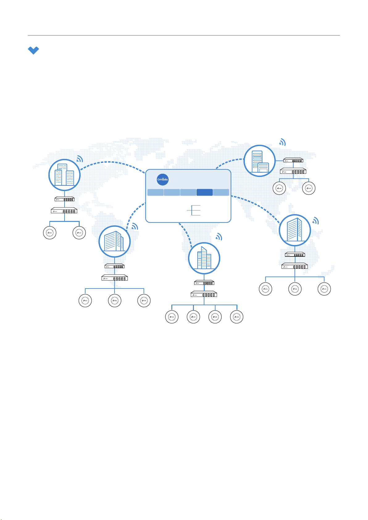
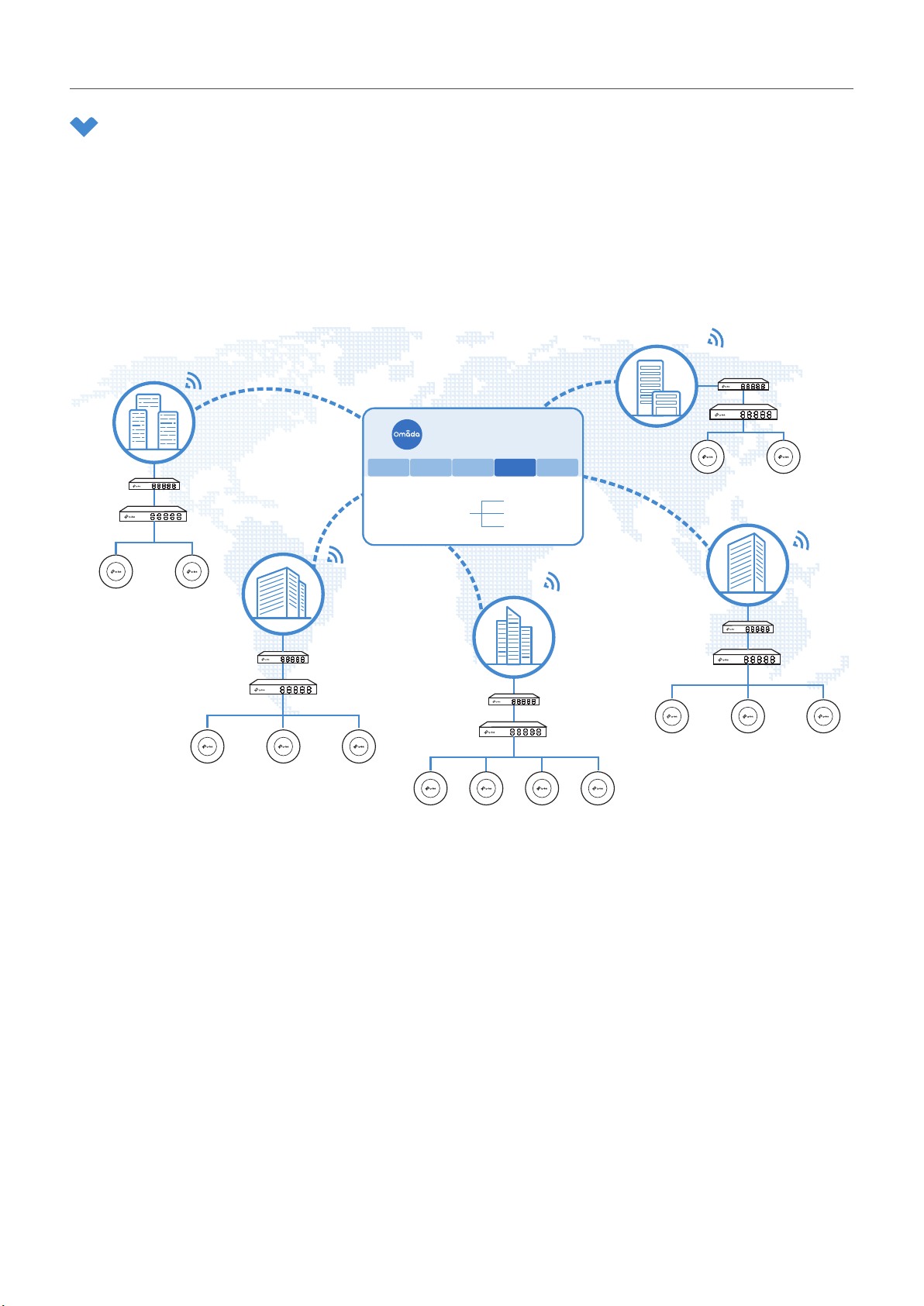
Omada SDN Controller Solution is designed to provide business-class networking solutions for
demanding, high-traffic environments such as campuses, hotels, malls, and offices. Omada SDN
Controller Solution simplifies deploying and managing large-scale enterprise networks and offers easy
maintenance, ongoing monitoring, and flexible scalability.
This figure shows a sample architeture of an Omada SDN enterprise network:
Site D
Site C
Router
Switch
Omada SDN Controller
Site A Site B Site C Site D Site E
Router
Switch
Site B
Unied
Management from
One Interface
Gateways
Switches
Access Points
Site E
APAP
Site A
APAP
Router
Router
Switch
AP APAP
AP
AP AP
Router
Switch
AP
Switch
AP APAP
The interconnected elements that work together to deliver a unified enterprise network include: Omada
SDN Controller, gateways, switches, access points, and client devices. Beginning with a base of client
devices, each element adds functionality and complexity as the network is developing, interconnecting
with the elements above and below it to create a comprehensive, secure wired and wireless solution.
Omada SDN Controller is a command center and management platform at the heart of the Omada
network. With a single platform, the network administrators configure and manage enterprise networks
comprised of routers, switches, and wireless access points in batches. This unleashes new levels of
management to avoid complex and costly overprovisioning.
2
Page 9

Chapter 1
Omada SDN Controller Solution Overview
1. 2 Core Components
An Omada SDN network consists of the following core components:
■ Omada SDN Controller—a command center and management platform at the heart of Omada
network solution for the enterprise. With a single platform, the network administrators configure
and manage all Omada products which have all your needs covered in terms of routing, switching
and Wi-Fi.
■ Gateways—boast excellent data processing capabilities and an array of powerful functions,
including IPsec/OpenVPN/PPTP/L2TP VPN, Load Balance, and Bandwidth Control, which are ideal
for the business network where a large number of users require a stable, secure connection.
■ Switches—offer flexible and cost-effective network solution with powerful Layer 2 features and
PoE options. Advanced features such as Access Control, QoS, LAG and Spanning Tree will satisfy
advanced business networks.
■ Access Points (Omada EAPs)—satisfy the mainstream Wi-Fi Standard and address your highdensity access needs with TP-Link’s innovation to help you build the versatile and reliable wireless
network for all business applications.
Omada SDN Controller
Tailored to different needs and budgets, Omada SDN Controller offers diverse deployment solutions.
Omada Software Controller, Omada Hardware Controller, and Omada Cloud-Based Controller, each
have their own set of advantages and applications.
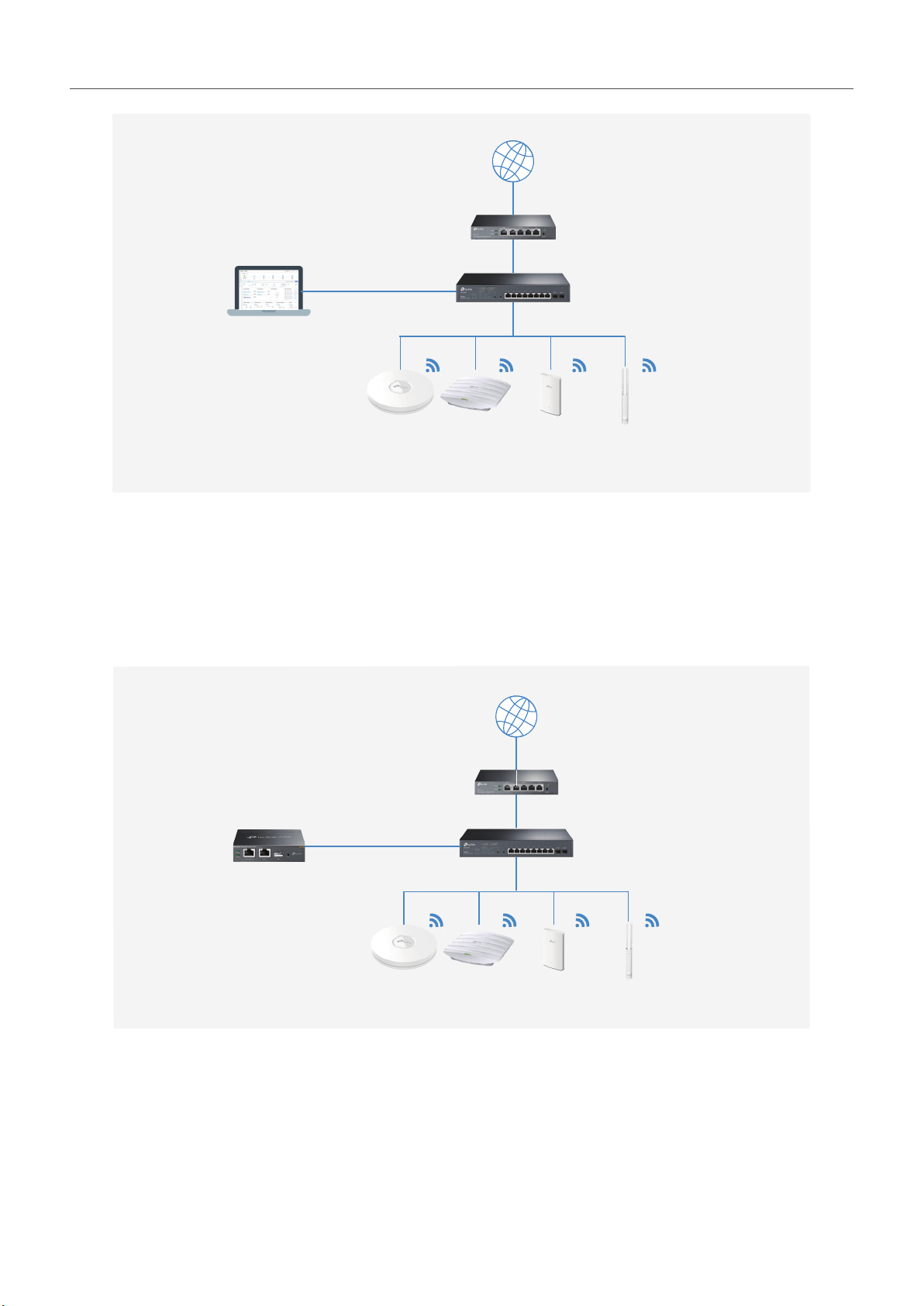
■ Omada Software Controller
Omada Software Controller is totally free, as well as all upgrades. The controller can be hosted on
any computers with Windows or Linux systems on your network.
3
Page 10
Chapter 1
Omada Software Controller
■ Omada Hardware Controller
Omada SDN Controller Solution Overview
Internet
SafeStream Gateway
JetStream Switch
Omada Access Points
Omada Hardware Controller is the management device which is pre-installed with Omada Software
Controller. You just need to pay for the device, then the built-in Omada Controller software is free
to use, no license fee or extra cost required. About the size of a mobile phone, the device is easy to
deploy and install on your network.
Internet
SafeStream Gateway
JetStream Switch
Omada Hardware Controller
Omada Access Points
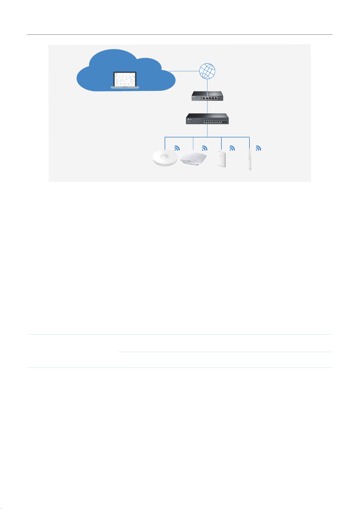
■ Omada Cloud-Based Controller
Omada Cloud controller is deployed on the Omada Cloud server, providing paid license service
with tiered pricing. With paid licienses bound to the devices on the controller, you can configure and
manage the devices via Omada Cloud Service. And you need not purchase an additional hardware
device or install the software on the host.
4
Page 11
Chapter 1
Omada SDN Controller Solution Overview
Omada Cloud Server
Internet
Omada Cloud Controller
Omada Access Points
SafeStream Gateway
JetStream Switch
The controllers differ in forms, but they have almost the same browser–based management interface
and serve the same functions of network management. In this guide, Omada Software Controller,
Omada Hardware Controller, and Omada Cloud-Based Controller are referred to as the controller,
unless we mention otherwise.
Omada Managed Gateways
TP-Link’s SafeStream VPN Router supports Gigabit Ethernet connections on both WAN and LAN ports
which keep the data moving at top speed. Including all the routing and network segmentation functions
that a business router must have, SafeStream VPN Router will be the backbone of the Omada SDN
network. Moreover, the router provides a both secure and easy approach to deploy site-to-site VPN
tunnels and access for remote clients.
Managing the gateway centrally through Omada SDN Controller is available on certain models only.
The following table provides specific information of the router which can be managed by the controller.
Omada Supported Gateways TL-R605(UN) V1 (default factory version or above)
TL-ER7206(UN) V1 (default factory version or above)
Omada Managed Switches
TP-Link’s JetStream Switch provides high-performance and enterprise-level security strategies and a
numble of advanced features, which is ideal access-edge for the Omada SDN network.
Managing the switch centrally through Omada SDN Controller is available on certain models only. The
following table provides specific information of the switch which can be managed by the controller.
5
Page 12

Chapter 1
Omada Supported Switches TL-SG2210MP V1 (default factory version or above)
TL-SG2428P V1 (default factory version or above)
TL-SG2008P V1 (default factory version or above)
TL-SG2008 V3 (version 3.0.0 or above)
TL-SG2210P V3.20 (version 3.2.0 or above)
TL-SL2428P V4.20 (default factory version or above)
TL-SG2218 V1(default factory version or above)
TL-SG3210 V3(default factory version or above)63
TL-SG3428 V1 (default factory version or above)
TL-SG3428MP V1 (default factory version or above)
Omada SDN Controller Solution Overview
TL-SG3452 V1 (default factory version or above)
TL-SG3452P V1 (default factory version or above)
TL-SG3428X V1 (default factory version or above)
TL-SG3428XMP V1 (default factory version or above)
TL-SG3210XHP-M2 V1 (default factory version or above)
6
Page 13

Chapter 1
Omada SDN Controller Solution Overview
Omada Access Points
TP-Link’s Omada Access Point provides business-class Wi-Fi with superior performance and range
which guarantees reliable wireless connectivity for the Omada SDN network.
Managing the access points centrally through Omada SDN Controller is available on certain models
only. The following table provides specific information of the access points which can be managed by
the controller.
Omada Supported APs EAP660 HD V1 (default factory version or above)
EAP620 HD V1 (default factory version or above)
EAP265HD V1 (default factory version or above)
EAP245 V3 (2.20.0 Build 20200423 or above)
EAP235-Wall (1.0.1 Build 20200618 or above)
EAP230-Wall (1.0.0 Build 20200618 or above)
EAP225 V3 (2.20.0 Build 20200630 or above)
EAP225-Wall V2 (1.20.0 Build 20200422 or above)
EAP225-Outdoor V1 (1.20.0 Build 20200422 or above)
EAP115 V4 (3.20.0 Build 20200525 or above)
EAP115-Wall V1 (1.20.0 Build 20200619 or above)
EAP110 V4 (3.20.0 Build 20200525 or above)
EAP110-Outdoor V3 (3.20.0 Build 20200511 or above)
7
Page 14

2
Get Started with Omada SDN
Controller
This chapter guides you on how to get started with Omada SDN Controller to configure the network.
Omada Software Controller, Omada Hardware Controller, and Omada Cloud-Based Controller differ in
forms, but they have almost the same browser–based management interface for network management.
Therefore, they have almost the same initial setup steps, including building your network topology,
deploying your controller, and logging in to the controller. The chapter includes the following sections:
• Set Up Your Software Controller
• Set Up Your Hardware Controller
• Set Up Your Cloud-Based Controller
Page 15
Chapter 2
Get Started with Omada SDN Controller
2. 1 Set Up Your Software Controller
Omada SDN Controller Solution is designed for scalable networks. Deployments and configurations
vary according to actual situations. Understanding your network requirements is the first step when
planning to provision any project. After you have identified these requirements, follow the steps below
to initially set up Omada Software Controller:
1 ) Determine the network topology.
2 ) Install Omada Software Controller.
3 ) Start and log in to the controller.
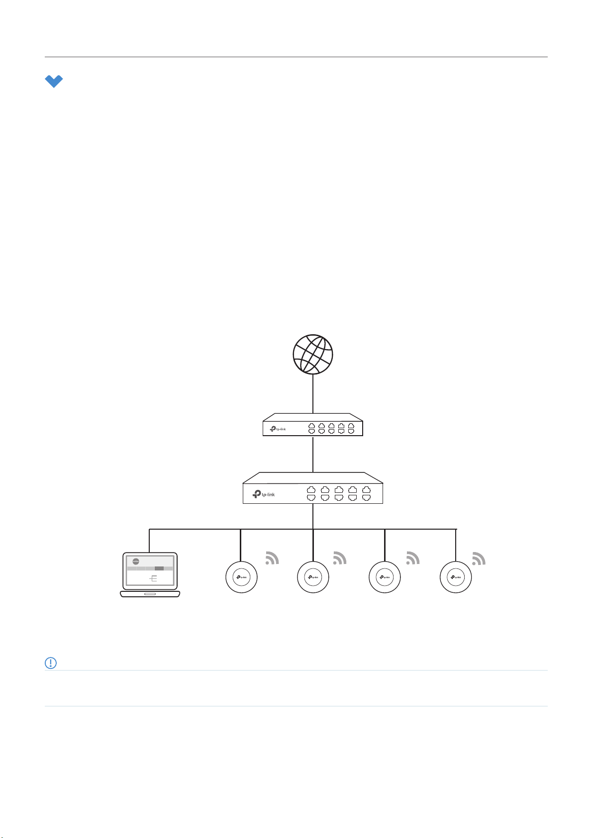
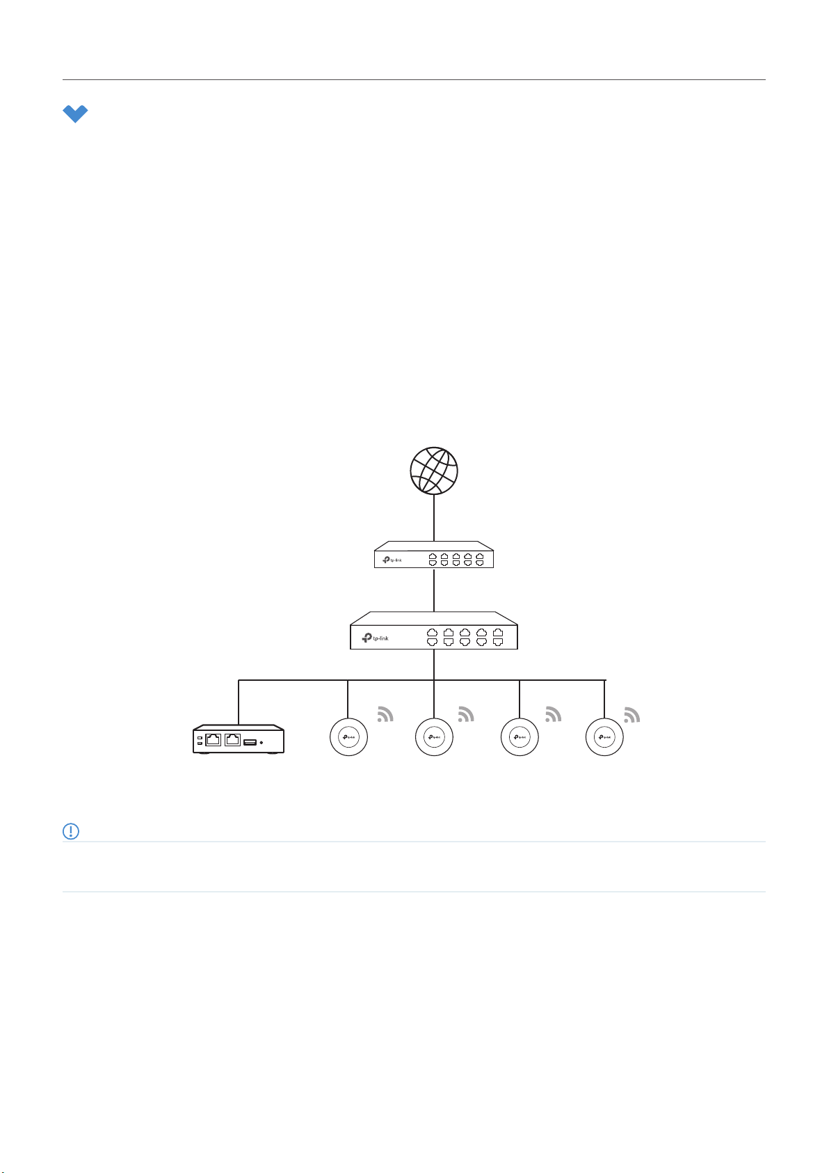
2. 1. 1 Determine the Network Topology
The network topology that you create for Omada SDN Controller varies depending on your business
requirements. The following figure shows a typical topology for a high-availability use case.
Omada SDN Controller
Site A Site B Site C Site D Site E
Unied
Gateways
Management from
Switches
One Interface
Access Points
Internet
SafeStream Gateway
JetStream Switch
Omada Access PointsOmada Software Controller
Note:
When using Omada SDN Controller, we recommend that you deploy the full Omada topology with supported TP-Link devices. If you use
third-party devices, Omada SDN Controller cannot discover and manage them.
9
Page 16

Chapter 2
Get Started with Omada SDN Controller
2. 1. 2 Install Omada Software Controller
Omada Software Controller is provided for both Windows and Linux operating systems. Determine
your operating system and follow the introductions below to install Omada Software Controller.
Installation on Windows Host
Omada Software Controller can be hosted on any computers with Windows systems on your network.
Make sure your PC’s hardware and system meet the following requirements, then properly install the
Omada Software Controller.
■ Hardware Requirements
Omada Software Controller can manage up to 1500 EAPs if the Controller Host has enough
hardware resources. To guarantee operational stability for managing 1500 EAPs, we recommend
that you use the hardware which meets or exceeds the following specifications:
CPU: Intel Core i3-8100, i5-6500, or i7-4700 with 2 or more cores and 4 or more threads.
Memory: 6 GB RAM or more.
■ System Requirements
Operating System: Microsoft Windows 7/8/10/Server. (We recommend that you deploy the
controller on a 64-bit operating system to guarantee the software stability.)
Web Browser: Mozilla Firefox 32 (or above), Google Chrome 37 (or above), Opera 24 (or above), or
Microsoft Internet Explorer 11 (or above).
■ Install Omada Software Controller
Download the installation file of Omada Software Controller from the website. Then follow the
instructions to properly install the Omada Software Controller. After a successful installation, a
shortcut icon of the Omada Software Controller will be created on your desktop.
Installation on Linux Host
Two versions of installation package are provided: .tar.gz file and .deb file. Both of them can be used in
multiple versions of Linux operating system, including Ubuntu, CentOS, Fedora, and Debian.
Make sure your PC’s hardware and system meet the following requirements, then choose the proper
installation files to install the Omada Software Controller.
■ Hardware Requirements
Omada Software Controller can manage up to 1500 EAPs if the Controller Host has enough
hardware resources. To guarantee operational stability for managing 1500 EAPs, we recommend
that you use the hardware which meets or exceeds the following specifications:
CPU: Intel Core i3-8100, i5-6500, or i7-4700 with 2 or more cores and 4 or more threads.
Memory: 6 GB RAM or more.
10
Page 17

Chapter 2
Get Started with Omada SDN Controller
■ System Requirements
Operating System: 64-bit Linux operating system, including Ubuntu 14.04/16.04/17.04/18.04,
CentOS 6.x/7.x, Fedora 20 (or above), and Debian 9.8.
Web Browser: Mozilla Firefox 32 (or above), Google Chrome 37 (or above), Opera 24 (or above), or
Microsoft Internet Explorer 11 (or above).
■ Install Omada Software Controller
Download the installation file of Omada Software Controller from the website. Check the
prerequisites and follow the steps based on your file version to install the controller. Here takes
Omada SDN Controller 4.2.8 as the example.
• Prerequisites for installing
To successfully install Omada Software Controller, ensure that you have performed the following
tasks before your installation:
1. Ensure that the Java Runtime Environment (JRE) have been installed in your system. The
controller requires that the system have Java 8 installed. Download the file according to your
operating system from the website and follow the instructions to install the JRE.
For Ubuntu16.04 or above, you can use the command: apt-get install openjdk-8-jre-headless
to get the Java 8 installed.
2. Ensure that MongoDB has been installed in your system. The controller works when the system
runs MongoDB 3.0.15–3.6.18. Download the file according to your operating system from the
website and follow the instructions to install the MongoDB.
3. Ensure that you have jsvc and curl installed in your system before installation, which is vital to
the smooth running of the system. If your system does not have jsvc or curl installed, you can
install it manually with the command: apt-get install or yum install. For example, you can use
the command: apt-get install jsvc or yum install jsvc to get jsvc installed. And if dependencies
are missing, you can use the command: apt-get -f install to fix the problem.
• Install the .tar.gz file
1. Make sure your PC is running in the root mode. You can use this command to enter root mode:
sudo
2. Extract the tar.gz file using the command:
tar zxvf Omada_Controller_v4.2.8_linux_x64_targz.tar.gz
3. Install Omada Controller using the command:
sudo bash ./install.sh
• Install the .deb file
1. Make sure your PC is running in the root mode. You can use this command to enter root mode:
sudo
2. Install the .deb file using the command:
dpkg -i Omada_Controller_v4.2.8_linux_x64.deb
11
Page 18
Chapter 2
Get Started with Omada SDN Controller
If dependencies are missing during the installation, you can use the command: apt-fix-broken
install to fix the problem.
After installing the controller, use the following commands to check and change the status of the
controller.
1. tpeap start — start the controller, use the command.
2. tpeap stop — stop running the Omada Controller.
3. tpeap status — show the status of Controller.
For more detailed information about the installation on Linux hosts, refer to the installation
instructions.
Note:
• For installing the .tar.gz, if you want Omada Controller to run as a user (it runs as root by default) you should modify OMADA_
USER value in bin/control.sh.
• To uninstall Omada Controller, go to the installation path: /opt /tplink/EAPController, and run the command: sudo bash ./uninstall.
sh.
• During uninstallation, you can choose whether to back up the database. The backup folder is /opt /tplink/eap_db_backup.
• During installation, you will be asked whether to restore the database if there is any backup database in the folder /opt/tplink/
eap_db_backup.
2. 1. 3 Start and Log In to the Omada Software Controller
Launch Omada Software Controller and follow the instructions to complete the basic configurations,
and then you can log in to the management interface.
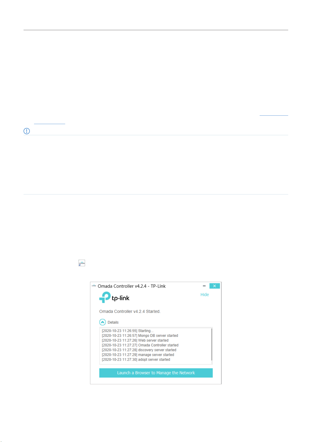
Launch Omada Software Controller
Double click the icon and the following window will pop up. You can click Hide to hide this window but
do not close it. After a while, your web browser will automatically open.
12
Page 19
Chapter 2
Get Started with Omada SDN Controller
Note:
• If your browser does not open automatically, click Launch a Browser to Manage the Network. You can also launch a web browser
and enter http://127.0.0.1:8088 in the address bar.
• If your web browser opens but prompts a problem with the website’s security certificate, click Continue.
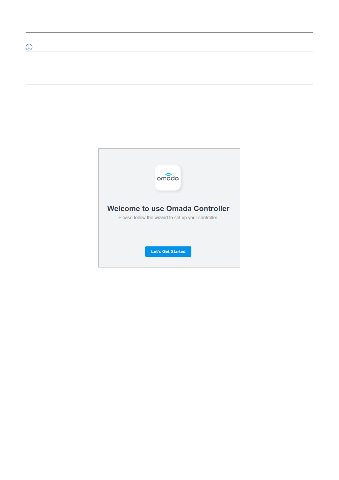
Do the Basic Configurations
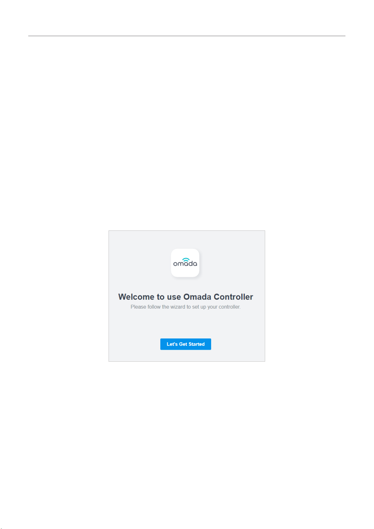
In the web browser, you can see the configuration page. Follow the setup wizard to complete the basic
settings for Omada Controller.
1. Click Let’s Get Started.
13
Page 20
Chapter 2
Get Started with Omada SDN Controller
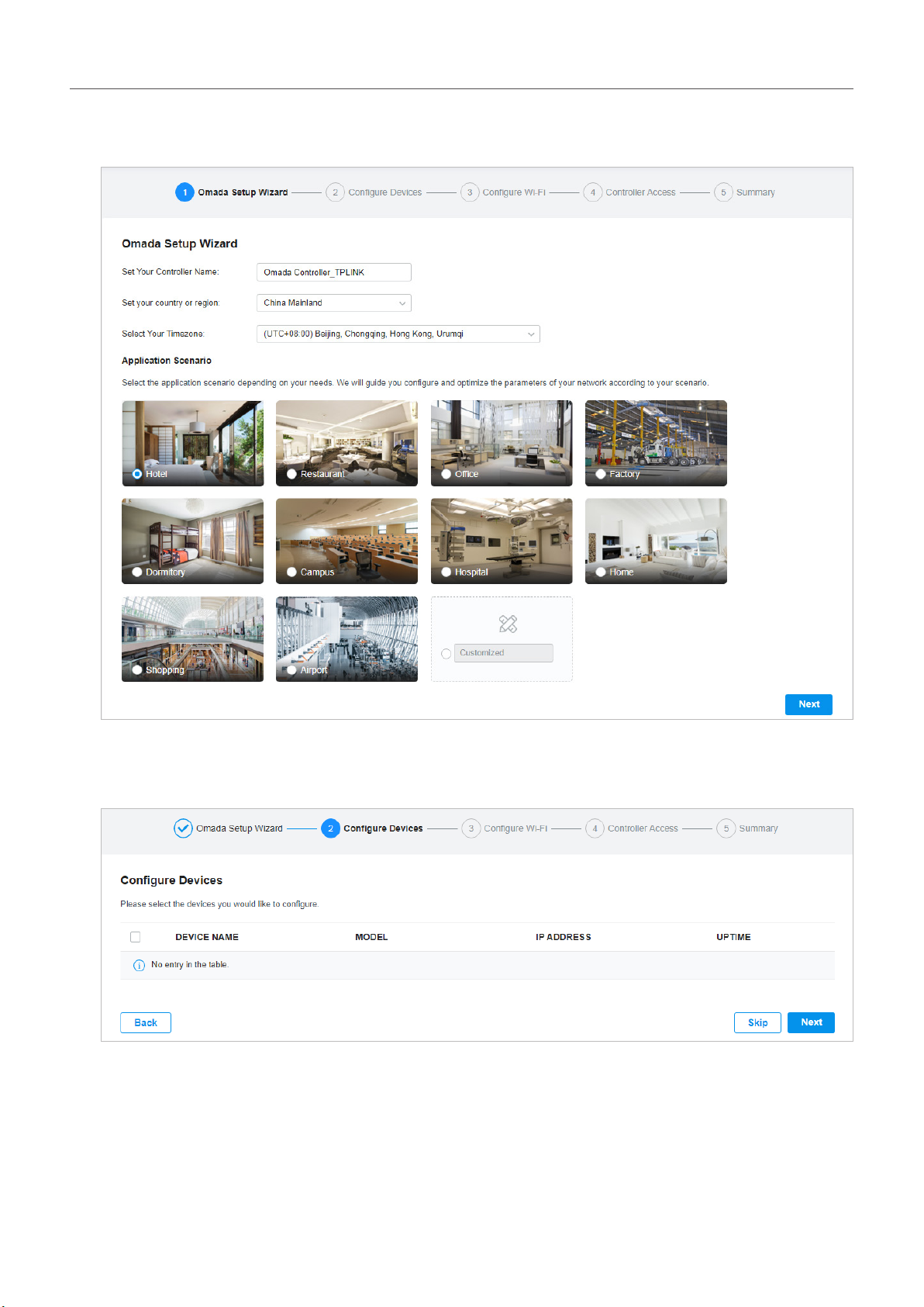
2. Specify a name for Omada Controller, and set your region and timezone. Then select the application
scenario depending on your needs. Click Next.
3. The setup page displays all the discovered devices in the network. Select one or more devices to
be managed and click Next.
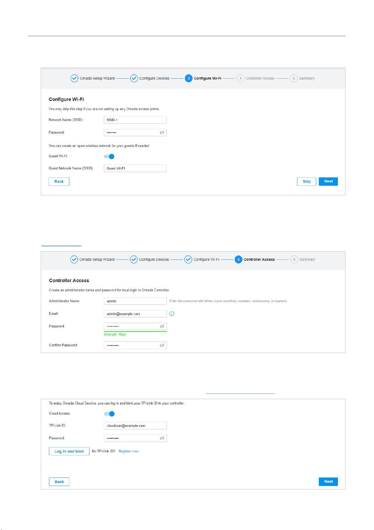
4. Set a wireless network name (SSID) and password for the EAPs to be managed. Omada Controller
will create two wireless networks, a 2.4GHz one and a 5GHz one, both encrypted in WPA-Personal
14
Page 21

Chapter 2
Get Started with Omada SDN Controller
mode. You can set Guest Wi-Fi to provide open Wi-Fi access for guests without disclosing your
main network if needed. Click Next.
5. Set a username and password for the login account. Specify the email address for resetting your
password in case that you forget the password. After logging in Omada Controller, set a mail server
so that you can receive emails and reset your password. For how to set a mail server, refer to
Notifications.
6. If you want to access the controller to manage networks remotely, enable the Cloud Access button,
and bind your TP-Link ID to your Omada Controller, and then click Next. If not, click Next directly.
For more details about Omada Cloud, please refer to Omada Cloud Service.
15
Page 22

Chapter 2
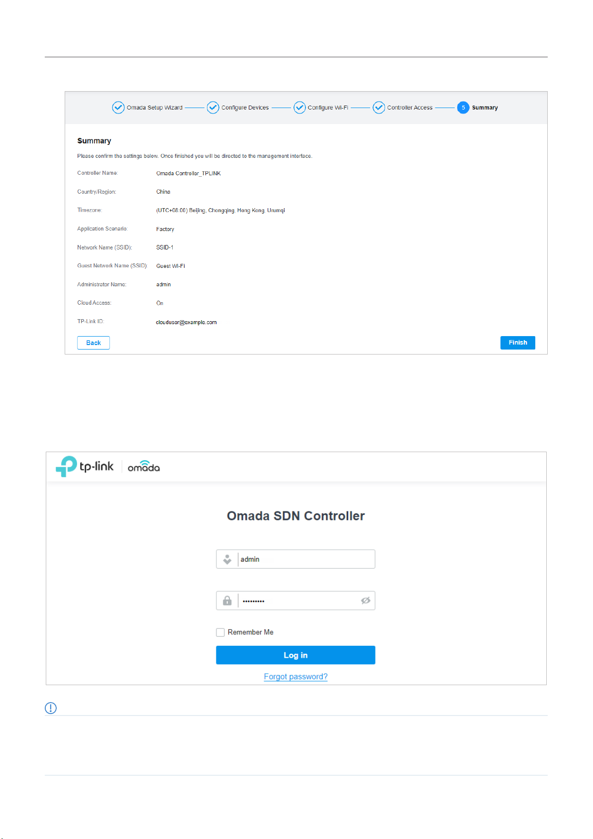
7. Review your settings and click Finish.
Get Started with Omada SDN Controller
Log In to the Management Interface
Once the basic configurations are finished, the browser will be redirected to the following page. Log in to
the management interface using the username and password you have set in the basic configurations.
Note:
In addition to the Controller Host, other hosts in the same LAN can also manage EAPs via remote access to the Controller Host. For
example, if the IP address of the Controller Host is 192.168.0.100 and Omada Controller is running normally on this host, you can enter
https://192.168.0.100:8043, or http://192.168.0.100:8088 in the web browser of other hosts in the same LAN to log in to the Omada
Controller and manage EAPs. Or you can log in to Omada Controller using other management devices through Omada Cloud service.
16
Page 23
Chapter 2
Get Started with Omada SDN Controller
2. 2 Set Up Your Hardware Controller
Omada SDN Controller Solution is designed for scalable networks. Deployments and configurations
vary according to actual situations. Understanding your network requirements is the first step when
planning to provision any project. After you have identified these requirements, follow the steps below
to initially set up Omada Hardware Controller:
1 ) Determine the network topology.
2 ) Deploy Omada Hardware Controller.
3 ) Start and log in to the controller.
2. 2. 1 Determine the Network Topology
The network topology that you create for Omada SDN Controller varies depending on your business
requirements. The following figure shows a typical topology for a high-availability use case.
Internet
SafeStream Gateway
JetStream Switch
Omada Access PointsOmada Hardware Controller
Note:
When using Omada SDN Controller, we recommend that you deploy the full Omada topology with supported TP-Link devices. If you use
third-party devices, Omada SDN Controller cannot discover and manage them.
2. 2. 2 Deploy Omada Hardware Controller
Omada Hardware Controller comes with the pre-installed controller software, so installation is not
necessary. After deploying Omada Hardware Controller on your network infrastructure, proceed to
configure the controller.
17
Page 24
Chapter 2
Get Started with Omada SDN Controller
2. 2. 3 Start and Log in to the Controller
Log In to the Management Interface
Follow the steps below to enter the management interface of Omada Hardware Controller:
1. Make sure that your management device has the route to access the controller.
2. Check the DHCP server (typically a router) for the IP Address of the controller. If the controller fails
to get a dynamic IP address from the DHCP server, the default fallback IP address 192.168.0.253,
is used.
3. Launch a web browser and type the IP address of the controller in the address bar, then press Enter
(Windows) or Return (Mac).
Do the Basic Configurations
In the web browser, you can see the configuration page. Follow the setup wizard to complete the basic
settings for Omada Controller.
1. Click Let’s Get Started.
18
Page 25

Chapter 2
Get Started with Omada SDN Controller
2. Specify a name for Omada Controller, and set your region and timezone. Then select the application
scenario depending on your needs. Click Next.
3. The setup page displays all the discovered devices in the network. Select one or more devices to
be managed and click Next.
4. Set a wireless network name (SSID) and password for the EAPs to be managed. Omada Controller
will create two wireless networks, a 2.4GHz one and a 5GHz one, both encrypted in WPA-Personal
19
Page 26
Chapter 2
Get Started with Omada SDN Controller
mode. You can set Guest Wi-Fi to provide open Wi-Fi access for guests without disclosing your
main network if needed. Click Next.
5. Set a username and password for the login account. Specify the email address for resetting your
password in case that you forget the password. After logging in Omada Controller, set a mail server
so that you can receive emails and reset your password. For how to set a mail server, refer to
Notifications.
6. If you want to access the controller to manage networks remotely, enable the Cloud Access button,
and bind your TP-Link ID to your Omada Controller, and then click Next. If not, click Next directly.
For more details about Omada Cloud, please refer to Omada Cloud Service.
20
Page 27
Chapter 2
7. Review your settings and click Finish.
Get Started with Omada SDN Controller
Log In to the Management Interface
Once the basic configurations are finished, the browser will be redirected to the following page. Log in to
the management interface using the username and password you have set in the basic configurations.
Note:
In addition to the Controller Host, other hosts in the same LAN can also manage EAPs via remote access to the Controller Host. For
example, if the IP address of the Controller Host is 192.168.0.100 and Omada Controller is running normally on this host, you can enter
https://192.168.0.100:8043, or http://192.168.0.100:8088 in the web browser of other hosts in the same LAN to log in to the Omada
Controller and manage EAPs. Or you can log in to Omada Controller using other management devices through Omada Cloud service.
21
Page 28

Chapter 2
Get Started with Omada SDN Controller
2. 3 Set Up Your Cloud-Based Controller
Omada SDN Controller Solution is designed for scalable networks. Deployments and configurations
vary according to actual situations. Understanding your network requirements is the first step when
planning to provision any project. After you have identified these requirements, follow the steps below
to initially set up Omada Cloud-Based Controller:
1 ) Launch a web browser and enter https://omada.tplinkcloud.com in the address bar. Enter your TP-
Link ID and password to log in. If you do not have a TP-Link ID, create a TP-Link ID first.
2 ) Click Add Controller and register for an Omada Cloud-Based Controller. Follow the instructions to
complete the setup process.
3 ) Add devices with the serial number, make sure the devices are online and in factory default.
4 ) Assign appropriate licenses in order to manage and configure the devices on the cloud-based
controller. Then wait until your controller is deployed
For detailed information about device-based licensing, refer to Know more about licensing.
Note:
Only when you have available licenses can you register for the Cloud-Based Controller and manage the devices. To successfully register
for a Cloud-Based Controller, purchase appropriate licenses.
22
Page 29

3
Manage Omada Managed Devices and
Sites
Start managing your network by creating sites and adopting devices so that you can configure and
monitor your devices centrally while keeping things organized. The chapter includes the following
sections:
• Create Sites
• Adopt Devices
Page 30
Chapter 3
Manage Omada Managed Devices and Sites
3. 1 Create Sites
Overview
Different sites are logically separated network locations, like different subsidiary companies or
departments. It’s best practice to create one site for each LAN (Local Area Network) and add all the
devices within the network to the site, including the router, switches and APs.
Site D
Site C
Router
Switch
LAN 4
APAP
LAN 3
Router
Switch
Site B
Omada SDN Controller
Site A Site B Site C Site D Site E
Unied
Management from
One Interface
Gateways
Switches
Access Points
Site E
Site A
APAP
Router
LAN 2
Router
Switch
LAN 1
AP APAP
AP
AP AP
Router
Switch
AP
LAN 5
Switch
AP APAP
Devices at one site need unified configurations, whereas those at different sites are not relative. To
make the best of a site, configure features simultaneously for multiple devices at the site, such as VLAN
and PoE Schedule for switches, and SSID and WLAN Schedule for APs, rather than set them up one by
one.
Configuration
To create and manage a site, follow these steps:
1 ) Create a site.
2 ) View and edit the site.
3 ) Go into the site.
24
Page 31

Chapter 3
Create a Site View and Edit the Site Go Into the Site
Manage Omada Managed Devices and Sites
To create a site, choose one from the following methods according to your needs.
■ Create a site from scratch
1. Click + Add New Site in the drop-down list of Sites. Alternatively, click in the
drop-down list of Sites and click in the Site Management page.
2. Enter a Site Name to identify the site, and configure other parameters according to where the
site is located. Then click Apply. The new site is added to the drop-down list of Sites, and the
table in the Site Management page as well.
■ Copy an existing site
You can quickly create a site based on an existing one by copying its site configuration, wired
configuration, and wireless configuration among others. After that, you can flexibly modify the new
site configuration to make it different from the old.
1. Click in the drop-down list of Sites. In the Site Management page, click in the
ACTION column of the site which you want to copy.
2. Enter a Site Name to identify the new site. Click Apply. The new site is added to the drop-down
list of Sites, and the table in the Site Management page as well.
25
Page 32

Chapter 3
Manage Omada Managed Devices and Sites
■ Import a site from another controller
If you want to migrate seamlessly from an old controller to a new one, import the site configuration
file of the old controller into the new. Before that, you need to export the site configuration file from
the old controller, which is covered in Site Migration.
1. Click in the drop-down list of Sites. Alternatively, click in the dropdown list of Sites and click in the Site Management page.
2. Enter a Site Name to identify the site. Browse your file explorer and choose a site configuration
file. Click Import. The new site is added to the drop-down list of Sites, and the table in the Site
Management page as well.
Create a Site View and Edit the Site Go Into the Site
After you create the site, you can click in the drop-down list of Sites, and view the site
status in the Site Management page. You can click in the ACTION column to edit the site configuration.
You can click in the ACTION column to delete the site.
Create a Site View and Edit the Site Go Into the Site
To monitor and configure a site, you need first go into the site.
26
Page 33

Chapter 3
Manage Omada Managed Devices and Sites
1. Select the site from the drop-down list of Sites to go into the site.
2. The Site field indicates the site which you are currently in. Some configuration items in the menu
are applied to the site which you are currently in, whereas others are applied to the whole controller.
27
Page 34

Chapter 3
Manage Omada Managed Devices and Sites
3. 2 Adopt Devices
Overview
After you create a site, add your devices to the site by making the controller adopt them. Make sure that
your devices in each LAN are added to the corresponding site so that they can be managed centrally.
Site D
Site C
Router
Switch
LAN 4
APAP
LAN 3
Router
Switch
Site B
Omada SDN Controller
Site A Site B Site C Site D Site E
Unied
Management from
One Interface
Gateways
Switches
Access Points
Site E
Site A
APAP
Router
Switch
LAN 2
LAN 1
AP APAP
AP
AP AP
Configuration
Choose a procedure according to the type of your controller:
■ For Omada Software Controller / Omada Hardware Controller
■ For Omada Cloud-Based Controller
Router
Switch
Router
Switch
LAN 5
AP APAP
AP
3. 3. 1 For Omada Software Controller / Omada Hardware Controller
To adopt the devices on the controller, follow these steps:
1 ) Prepare for communication between the controller and devices.
2 ) Prepare for device discovery.
3 ) Adopt the devices.
28
Page 35

Chapter 3
Prepare for Communication Prepare for Device Discovery Adopt the Devices
Manage Omada Managed Devices and Sites
Note:
If the controller and devices are in the same LAN, subnet and VLAN, skip this step.
Make sure that the controller can communicate with the devices. Otherwise, the controller cannot
discover or adopt the devices by any means. If the controller and devices are in different LANs, subnets
or VLANs, use the following techniques to build up the connection according to your scenario.
29
Page 36

Chapter 3
VLAN 1 VLAN 2
Subnet 1: 192.168.0.0/24 Subnet 2: 192.168.1.0/24
Manage Omada Managed Devices and Sites
1. Set up the Network
■ Scenario 1: Across VLANs or Subnets
As shown in the following figures, the controller and devices are in different VLANs or subnets. You need
to set up a layer 3 interface for each VLAN or subnet, and make sure the interfaces can communicate
with each other.
Internet
Gateway
Interface 1 Interface 2
Switch
Omada SDN Controller
Site
Unied
Management from
One Interface
Gateway
Switch
APs
AP AP
Internet
Gateway
Interface 1 Interface 2
Switch
Omada SDN Controller
Site
Unied
Management from
One Interface
Gateway
Switch
APs
AP AP
■ Scenario 2: Across LANs
As shown in the following figure, the controller and devices are in different LANs. You need to
establish communication across the internet and the gateways.
By default, devices in LAN 1 cannot communicate with the controller in LAN 2, because Gateway B
is in front of the controller and block access to it. To make the controller accessible to the devices,
you can use Port Forwarding or VPN.
30
Page 37

Chapter 3
LAN 1 LAN 2
Manage Omada Managed Devices and Sites
• Use Port Forwarding
Configure Port Forwarding on Gateway B and open port 29810-29813 for the controller, which are
essential for discovering and adopting devices. If you are using firewalls in the networks, make sure
that the firewalls don’t block those ports.
Internet
Port Forwarding
Gateway A
Switch
AP AP
Omada SDN Controller
Site
Unied
Management from
One Interface
Gateway B
Gateway
Switch
APs
To configure Port Forwarding on Gateway B, you need first adopt Gateway B on the controller. For
how to adopt Gateway B, refer to Adopt the Devices. Go to Settings > Transmission > NAT > Port
Forwarding. Click + Create New Rule to load the following page. Specify a name to identify the Port
Forwarding rule, check Enable for Status, select Any as Source IP, select the desired WAN port
31
Page 38

Chapter 3
Manage Omada Managed Devices and Sites
as Interface, disable DMZ, specify 29810-29813 as Source Port and Destination Port, specify the
controller’s IP address as Destination IP, and select All as Protocol. Then click Create.
32
Page 39

Chapter 3
LAN 1 LAN 2
Manage Omada Managed Devices and Sites
• Use VPN
Set up a VPN connection between Gateway A and Gateway B in Standalone Mode. For details about
VPN configuration, refer to the User Guide of the gateways.
Internet
VPN Connection
VPNVPN
Gateway A
Gateway B
Switch
Omada SDN Controller
Site
Unied
Management from
One Interface
Gateway
Switch
APs
AP AP
2. (Optional) Test the network
If you are not sure whether the controller and devices can establish communication, it’s
recommended to do the ping test from the devices to the controller.
Let’s take a switch for example. Log into the web page of the switch in Standalone Mode. Then Go
to MAINTENANCE > Network Diagnostics > Ping to load the following page, and specify Destination
33
Page 40

Chapter 3
Manage Omada Managed Devices and Sites
IP as the IP address of the controller (if you have configured Port Forwarding on the controller side,
use the public WAN IP address of the gateway instead). Then click Ping.
If the ping result shows the packets are received, it implies that the controller can communicate
with the devices. Otherwise, the controller cannot communicate with the devices, then you need to
check your network.
Prepare for Communication Prepare for Device Discovery Adopt the Devices
Note:
If the controller and devices are in the same LAN, subnet and VLAN, skip this step. In this scenario, the controller can discover the
devices directly, and no additional settings are required.
Make sure that the controller can discover the devices.
When the controller and devices are in different LANs, subnets or VLANs, the controller cannot discover
the devices directly. You need to choose Controller Inform URL, Discovery Utility, or DHCP Option 138
as the method to help the controller discover the devices.
■ Controller Inform URL
Controller Inform URL informs the devices of the controller’s URL or IP address. Then the devices
make contact with the controller so that the controller can discover the devices.
34
Page 41

Chapter 3
Manage Omada Managed Devices and Sites
You can configure Controller Inform URL for devices in Standalone Mode. Let’s take a switch for
example. Log into the management page of the switch in Standalone Mode and go to SYSTEM
> Controller Settings to load the following page. In Controller Inform URL, specify Inform URL/
IP Address as the controller’s URL or IP address (if you have configured Port Forwarding on the
controller side, use the public WAN IP address of the gateway instead). Then click Apply.
■ Discovery Utility
Discovery Utility can discover the devices in the same LAN, subnet and VLAN, and inform the
devices of the controller’s IP address. Then the devices make contact with the controller so that
the controller can discover the devices.
1. Download Discovery Utility from the website and then install it on your PC which should be
located in the same LAN, subnet and VLAN as your devices.
35
Page 42

Chapter 3
Manage Omada Managed Devices and Sites
2. Open Discovery Utility and you can see a list of devices. Select the devices to be adopted and
click Batch Setting.
3. Specify Controller Hostname/IP as the IP address of the controller (if you have configured Port
Forwarding on the controller side, use the public WAN IP address of the gateway instead), and
36
Page 43

Chapter 3
enter the username and password of the devices. By default, the username and password are
both admin. Then click Apply. Wait until the setting succeeds.
Manage Omada Managed Devices and Sites
■ DHCP Option 138
DHCP Option 138 informs a DHCP client, such as a switch or an EAP, of the controller’s IP address
when the DHCP client sends DHCP requests to the DHCP server, which is typically a gateway.
1. To use DHCP Option 138, you need to adopt the gateway on the controller first, which may
require other techniques like Controller Inform URL or Discovery Utility if necessary.
2. After the gateway is adopted, go to Settings > Wired Networks > LAN > Networks, and click
in the ACTION column of the LAN where the DHCP clients are located. Enable DHCP Server and
configure common DHCP parameters. Then click Advanced DHCP Options and specify Option
37
Page 44

Chapter 3
138 as the controller’s IP address (if you have configured Port Forwarding on the controller side,
use the public WAN IP address of the gateway instead). Click Save.
Manage Omada Managed Devices and Sites
3. To make DHCP Option 138 take effect, you need to renew DHCP parameters for the DHCP
clients. One possible way is to disconnect the DHCP clients and then reconnect them.
38
Page 45
Chapter 3
Prepare for Communication Prepare for Device Discovery Adopt the Devices
Manage Omada Managed Devices and Sites
1. Decide which site you want to add the devices to. On the controller configuration page, select the
site from the drop-down list of Sites.
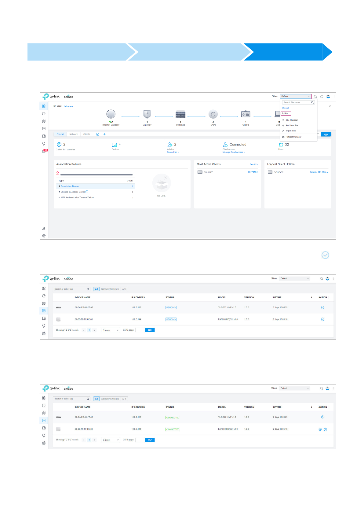
2. Go to Devices, and devices which have been discovered by the controller are displayed. Click in
the ACTION column of the devices which you want to add to the site.
3. Wait until the STAT US turns into Connected. Then the devices are adopted by the controller and
added to the current site. Once the devices are adopted, they are subject to central management
in the site.
39
Page 46

Chapter 3
LAN 1
Manage Omada Managed Devices and Sites
3. 3. 2 For Omada Cloud-Based Controller
To adopt the devices on the controller, follow these steps:
1 ) Connect to the internet.
2 ) Prepare for controller management.
3 ) Adopt the devices.
Connect to the Internet Prepare for Controller Management Adopt the Devices
1. Set up the network.
Make sure that your devices are connected to the internet.
Omada SDN Controller
Site
Unied
Management from
One Interface
Gateway
Switch
APs
Internet
Gateway A
Switch
AP AP
If you are using firewalls in your network, make sure that the firewall doesn’t block traffic from the
controller. To configure your firewall policy, you may want to know the URL of the controller. After
you open the web page of the controller, you can get the URL from the address bar of the browser.
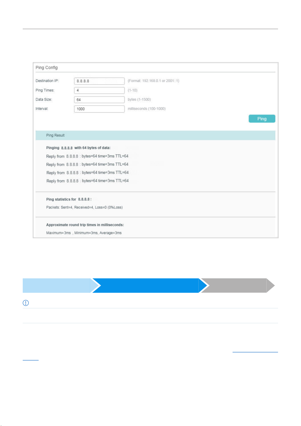
2. (Optional) Test the network.
If you are not sure whether the devices are connected to the internet, it’s recommended to do the
ping test from the devices to a public IP address, such as 8.8.8.8.
40
Page 47
Chapter 3
Manage Omada Managed Devices and Sites
Let’s take a switch for example. Log into the web page of the switch in Standalone Mode. Go to
MAINTENANCE > Network Diagnostics > Ping to load the following page. Specify Destination IP as
a public IP address, such as 8.8.8.8. Then click Ping.
If the ping result shows the packets are received, it implies that the devices are connected to the
internet. Otherwise, the devices are not connected to the internet, then you need to check your
network.
Connect to the Internet Prepare for Controller Management Adopt the Devices
Note:
If your devices are on the factory default setting, skip this step.
The Cloud-Based Controller Management feature allows the devices to be adopted by Omada CloudBased Controller. Make sure Cloud-Based Controller Management is enabled on the devices. For
details, refer to the User Guide of your devices, which can be downloaded from the TP-Link download
center.
41
Page 48

Chapter 3
Manage Omada Managed Devices and Sites
Let’s take a switch for example. Log into the web page of the switch in Standalone Mode. Go to SYSTEM
> Controller Settings to load the following page. In Cloud-Based Controller Management, enable Cloud-
Based Controller Management and click Apply.
Connect to the Internet Prepare for Controller Management Adopt the Devices
On the controller configuration page, go into the site where you want to add the devices. Go to Devices
and click Add Devices. Then add your devices to the controller. Once the devices are adopted, they are
subject to central management in the site.
42
Page 49

4
Congure the Network with Omada
SDN Controller
This chapter guides you on how to configure the network with Omada SDN Controller. As the command
center and management platform at the heart of the Omada network, Omada SDN Controller provides
a unified approach to configuring enterprise networks comprised of routers, switches, and wireless
access points. The chapter includes the following sections:
• Navigate the UI
• Modify the Current Site Configuration
• Configure Wired Networks
• Configure Wireless Networks
• Network Security
• Transmission
• Configure VPN
• Create Profiles
• Authentication
• Services
Page 50

Chapter 4
ConguretheNetworkwithOmadaSDNController
4. 1 Navigate the UI
As you start using the management interface of the controller (Controller UI) to configure and monitor
your network, it is helpful to familiarize yourself with the most commonly-used elements of the Controller
UI that are frequently referenced in this guide.
The Controller UI is grouped into task-oriented menus, which are located in the top right-hand corner
and the left-hand navigation bar of the page. Note that the settings and features that appear in the
UI depend on your user account permissions. The following image depicts the main elements of the
Controller UI.
The elements in the top right corner of the screen give quick access to:
Site Management
Site, which means logically separated network location, is the largest unit for managing networks with Omada SDN
Controller. You can simultaneously configure features for multiple devices at a site. The Site Management includes:
Site Manager — haveaquickoverviewofsites,includingthename,location,manageddevices,andconnectedclients.
Add New Site — addanew site,whichisthe logicallyseparatednetworklocation. Thesiteisthe largestunitfor
managing the network.
Import Site — importthesitefromanothercontroller.
44
Page 51

Chapter 4
Global Search Feature
Click and enter the keywords to quickly look up the functions that you want to configure.
My Account
Click the account icon to display account information, Account Settings and Log Out. You can change your
password on Account Settings.
More Settings
Click to display Preferences, About and Tutorial.
Preferences: Click to jump to Maintenance and customize the Controller UI depending on your needs. For details, refer
to Maintenance
About: Click to display the controller version.
Tutorial: Click to view the quick Getting Started guide which demonstrates the navigation and tools available for the
controller.
ConguretheNetworkwithOmadaSDNController
45
Page 52

Chapter 4
The left-hand navigation bar provides access to:
Dashboard displays a summarized view of the network status through different
visualizations. The widget-driven dashboard is customizable depending on your needs.
Statistics provides a visual representation of the clients and network managed by the
controller. The run charts show changes in device performances over time, including the
status of switches and speed test results.
Map generates the system topology automatically and you can look over the provisioning
status of devices. By clicking on each node, you can view the detailed information of each
device. You can also upload images of your location for a visual representation of your
network.
Devices displays all TP-Link devices discovered on the site and their general information.
This list view can change depending on your monitoring needs through customizing the
columns. You can click any device on the list to reveal the Properties window for more
detailed information of each device and provisioning individual configurations to the device.
Clients displays a list view of wired and wireless clients that are connected to the network.
This list view can change depending on your monitoring need through customizing the
columns. You can click any clients on the list to reveal the Properties window for more
detailed information of each client and provisioning individual configurations to the client.
ConguretheNetworkwithOmadaSDNController
Insight displays a list of statistics of your network device, clients and services during a
specified period. You can change the range of date in one-day increments.
Log displays logs that record varied activities of users, devices, and systems events,
such as administrative actions and abnormal device behaviors. You can also configure
notifications to receive alert emails of certain activities.
Admin allows you to configure multi-level administrative accounts with a hierarchy of
permissions that can be configured to provide finely grained levels of access to the
controller as required by your enterprise.
Settings is divided to two parts: Site Settings and Controller Settings. In Site Settings,
you can provision and configure all your network devices on the same site in minutes. In
Controller Settings, you can maintain the controller system for best performance.
46
Page 53

Chapter 4
ConguretheNetworkwithOmadaSDNController
4. 2 Modify the Current Site Configuration
You can view and modify the configurations of the current site in Site, including the basic site
information, centrally-managed device features, and the device account. The features and device
account configured here are applied to all devices on the site, so you can easily manage the devices
centrally.
4. 2. 1 Site Configuration
Overview
In Site Configuration, you can view and modify the site name, location, time zone, and application
scenario of the current site.
Configuration
Select a site from the drop down list of Sites in the top-right corner, go to Settings > Site, and configure
the following information of the site in Site Configuration. Click Save.
Site Name Specify the name of the current site. It should be no more than 64 characters.
Country/Region Select the location of the site.
Time Zone Select the time zone of the site.
Application Scenario Specify the application scenario of the site. To customize your scenario, click Create New
Scenario in the drop-down list.
4. 2. 2 Services
Overview
In Services, you can view and modify the features applied to devices on the current site. Most features
are applied to all devices, such as LED, Automatic Upgrades, and Alert Emails, while some are applied
to EAPs only, such as Channel Limit and Mesh.
47
Page 54

Chapter 4
ConguretheNetworkwithOmadaSDNController
Configuration
Select a site from the drop down list of Sites in the top-right corner, go to Settings > Site, and configure
the following features for the current site in Services. Click Save.
LED Enable or disable LEDs of all devices in the site.
By default, the device follows the LED setting of the site it belongs to. To change the LED
setting for certain devices, refer to Configure and Monitor Omada Managed Devices.
Automatic Upgrades When enabled, the controller will automatically upgrade devices in this site to the latest
version.
Channel Limit (For Outdoor APs) When enabled, outdoor EAPs do not use the channel with the frequency
ranging from 5150 MHz to 5350 MHz to meet the local laws and regulations limit in EU
countries.
Mesh (For EAP225/EAP245/EAP225-Outdoor) When enabled, EAPs supporting Mesh can
establish the mesh network at the site.
Auto Failover (For APs in the mesh network) Auto Failover is used to automatically maintain the mesh
network. When enabled, the controller will automatically select a new wireless uplink for the
AP if the original uplink fails.
To enable this feature, enable Mesh first.
48
Page 55

Chapter 4
Connectivity Detection (For APs in the mesh network) Specify the method of Connection Detection when mesh is
Full-Sector DFS (For APs in the mesh network) With this feature enabled, when radar signals are detected
Periodic Speed Test When enabled, the controller tests and records the speed and latency of WAN ports
enabled.
In a mesh network, the APs can send ARP request packets to a fixed IP address to test the
connectivity. If the link fails, the status of these APs will change to Isolated.
Auto (Recommended): Select this method and the mesh APs will send ARP request packets
to the default gateway for the detection.
Custom IP Address: Select this method and specify a desired IP address. The mesh APs
will send ARP request packets to the custom IP address to test the connectivity. If the IP
address of the AP is in different network segments from the custom IP address, the AP will
use the default gateway IP address for the detection.
on current channel by one EAP, the other EAPs in the mesh network will be also informed.
Then all EAPs in the mesh network will switch to an alternate channel.
To enable this feature, enable Mesh first.
periodically.
ConguretheNetworkwithOmadaSDNController
Speed Test Interval: When enabled, specify the interval to decide how often to test the
speed of devices.
Speed Test History: Click it to view the history statistics of speed test in Speed Test
Statistics.
Alert Emails Enable alert emails: When enabled, the controller can send emails to notify the
administrators and viewers of the site’s alert logs once generated.
Send similar alerts within seconds in one email: When enabled, the similar alerts generated
in each time period are collected and sent to administrators and viewers in one email.
To configure alert-level logs and enable email notifications on the controller, refer to
Notifications.
Remote Logging With this feature configured, the controller will send generated system logs to the log
server. When enabled, the following items are required:
Syslog Server IP/Hostname: Enter the IP address or hostname of the log server.
Syslog Server Port: Enter the port of the server.
Client Detail Logs: With this feature enabled, the logs of clients will be sent to the syslog
server.
Advanced Features (For APs) When enabled, you can configure more features for APs in Advanced Features.
When disabled, these features keep the default settings.
For detailed configuration, refer to Advanced Features.
49
Page 56

Chapter 4
ConguretheNetworkwithOmadaSDNController
4. 2. 3 Advanced Features
Overview
Advanced features include Fast Roaming, Band Steering, and Beacon Control, which are applicable to
APs only. With these advanced features configured properly, you can improve the network’s stability,
reliability and communication efficiency.
Advanced features are recommended to be configured by network administrators with the WLAN
knowledge. If you are not sure about your network conditions and the potential impact of all settings,
keep Advanced Features disabled in Services to use their default configurations.
Configuration
Select a site from the drop down list of Sites in the top-right corner, go to Settings > Site, and enable
Advanced Features in Services first. Then configure the following features in Advanced Features. Click
Save.
50
Page 57

Chapter 4
Fast Roaming With this feature enabled, clients that support 802.11k/v can improve fast roaming
Dual Band 11k Report When disabled, the controller provides neighbor list that contains only neighbor APs in the
Force-Disassociation With this feature disabled, the AP only issues an 802.11v roaming suggestion when a
experience when moving among different APs.
By default, it is disabled.
same band with which the client is associated.
When enabled, the controller provides neighbor list that contains neighbor APs in both
2.4 GHz and 5 GHz bands.
This feature is available only when Fast Roaming is enabled. By default, it is disabled.
client’s link quality drops below the predefined threshold and there is a better option of AP,
but whether to roam or not is determined by the client.
With this feature enabled, the AP will force disassociate the client if it does not re-associate
to another AP.
This feature is available only when Fast Roaming is enabled. By default, it is disabled.
ConguretheNetworkwithOmadaSDNController
Band Steering Band Steering can adjust the number of clients on 2.4 GHz and 5 GHz bands to provide
better wireless experience.
When enabled, dual-band clients will be steered to the 5 GHz band according to the
configured parameters. With appropriate settings, Band Steering can improve the network
performance because the 5 GHz band supports a larger number of non-overlapping
channels and is less noisy. By default, it is disabled.
Connection Threshold: Specify the maximum number of clients connected to the 5 GHz
band. By default, the threshold is 30.
Difference Threshold: Specify the maximum difference between the number of clients on
the 5 GHz band and 2.4 GHz band. By default, the threshold is 4.
When the connection number and difference of client number both exceed their configured
threshold, the EAP will refuse the connection request on 5 GHz band and no longer steers
other clients to the 5 GHz band.
Maximum Failures: Specify the maximum number of the failed attempts when a client
repeatedly tries to associate with an EAP on 5 GHz. When the number of rejections reaches
Maximum Failures, the EAP will accept the client’s request for connection. By default, it is 4.
51
Page 58
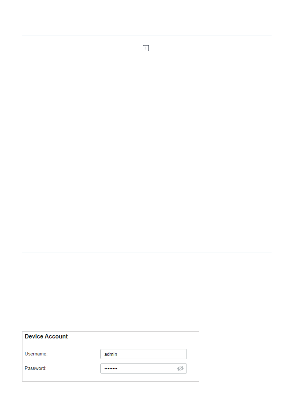
Chapter 4
Beacon Control Beacons are transmitted periodically by the EAP to announce the presence of a wireless
network for the clients. Click , select the band, and configure the following parameters
of Beacon Control.
Beacon Interval: Specify how often the APs send a beacon to clients. By default, it is 100.
DTIM Period: Specify how often the clients check for buffered data that are still on the EAP
awaiting pickup. By default, the clients check for them at every beacon.
DTIM (Delivery Traffic Indication Message) is contained in some Beacon frames indicating
whether the EAP has buffered data for client devices. An excessive DTIM interval may
reduce the performance of multicast applications, so we recommend that you keep the
default interval, 1.
RTS Threshold: RTS (Request to Send) can ensure efficient data transmission by avoiding
the conflict of packets. If a client wants to send a packet larger than the threshold, the RTS
mechanism will be activated to delay packets of other clients in the same wireless network.
We recommend that you keep the default threshold, which is 2347. If you specify a
low threshold value, the RTS mechanism may be activated more frequently to recover
the network from possible interference or collisions. However, it also consumes more
bandwidth and reduces the throughput of the packet.
ConguretheNetworkwithOmadaSDNController
Fragmentation Threshold: Fragmentation can limit the size of packets transmitted over the
network. If a packet to be sent exceeds the Fragmentation threshold, the Fragmentation
function will be activated, and the packet will be fragmented into several packets. By
default, the threshold is 2346.
Fragmentation helps improve network performance if properly configured. However, too
low fragmentation threshold may result in poor wireless performance because of the
increased message traffic and the extra work of dividing up and reassembling frames.
Airtime Fairness: With this option enabled, each client connecting to the EAP can get the
same amount of time to transmit data so that low-data-rate clients do not occupy too much
network bandwidth and network performance improves as a whole. We recommend you
enable this function under multi-rate wireless networks.
4. 2. 4 Device Account
You can specify a device account for all adopted devices on the site in batches. Once the devices
are adopted by the controller, their username and password become the same as settings in Device
Account to protect the communication between the controller and devices. By default, the username
is admin and the password is generated randomly.
Go to Settings > Site and modify the username and password in Device Account. Click Save and the
new username and password are applied to all devices on the site.
52
Page 59

Chapter 4
ConguretheNetworkwithOmadaSDNController
4. 3 Configure Wired Networks
Wired networks enable your wired devices and clients including the gateway, switches, EAPs and PCs
to connect to each other and to the internet.
As shown in the following figure, Wired Networks consist of two parts: Internet and LAN.
Wired Networks
LAN
Switch A
Switch C
Switch B
Internet
Internet
WAN Port
Omada Controller
LAN Port
Gateway
FTP Server
For Internet, you determine the number of WAN ports deployed by the gateway and how they connect
to the internet according to your needs. To connect to the internet, the gateway choose one from the
following connection types: Dynamic IP, Static IP, PPPoE, L2TP, and PPTP.
For LAN, you configure the wired internal network and how your devices logically separate from or
connect to each other by means of VLANs and interfaces. Advanced LAN features include IGMP
Snooping, DHCP Server and DHCP Options, PoE, Voice Network, 802.1X Control, Port Isolation,
Spanning Tree, LLDP-MED, and Bandwidth Control.
4. 3. 1 Set Up an Internet Connection
Configuration
To set up an internet connection, follow these steps:
1 ) Select WAN Mode.
2 ) Configure WAN Connections.
3 ) (Optional) Configure Load Balancing.
53
Page 60

Chapter 4
ConguretheNetworkwithOmadaSDNController
Select WAN Mode Configure WAN Connections (Optional) Configure Load Balancing
Go to Settings > Wired Networks > Internet to load the following page. In WAN Mode, configure the
number of WAN ports deployed by the gateway and other parameters. Then click Apply.
WAN Ports Click the check box to enable the port as a WAN port. To configure multiple WAN ports,
enable the ports one by one.
Online Detection Interval Select how often the WAN ports detect WAN connection status. If you don’t want to
enable online detection, select Disable.
Select WAN Mode Configure WAN Connections (Optional) Configure Load Balancing
Note:
The number of configurable WAN ports is decided by WAN Mode.
Go to Settings > Wired Networks > Internet. For WAN connections, choose a Connection Type according
to the service provided by your ISP.
Connection Type Dynamic IP: If your ISP automatically assigns the IP address and the corresponding parameters,
choose Dynamic IP.
Static IP: If your ISP provides you with a fixed IP address and the corresponding parameters,
choose Static IP.
PPPoE: If your ISP provides you with a PPPoE account, choose PPPoE.
L2TP: If your ISP provides you with an L2TP account, choose L2TP.
PPTP: If your ISP provides you with a PPTP account, choose PPTP.
54
Page 61

Chapter 4
ConguretheNetworkwithOmadaSDNController
■ Dynamic IP
1. Choose Connection Type as Dynamic IP and configure the following parameters.
MAC Address Use Default MAC Address: The WAN port uses the default MAC address to set up the
internet connection. It’s recommended to use the default MAC address unless required
otherwise.
Customize MAC Address: The WAN port uses a customized MAC address to set up the
internet connection and you need to specify the MAC address. Typically, this is required
when your ISP bound the MAC address with your account or IP address. If you are not sure,
contact the ISP.
55
Page 62

Chapter 4
ConguretheNetworkwithOmadaSDNController
2. Click + Advanced Settings and configure the following parameters. Then click Apply.
Unicast DHCP With this option enabled, the gateway will require the DHCP server to assign the
IP address by sending unicast DHCP packets. Usually you need not to enable the
option.
Primary DNS Server /
Secondary DNS Server
Host Name Enter a name for the gateway.
MTU Specify the MTU (Maximum Transmission Unit) of the WAN port.
VLAN Add the WAN port to a VLAN and you need to specify the VLAN. Generally, you
QoS Tag The QoS (Quality of Service) function helps to prioritize the internet traffic based
Enter the IP address of the DNS server provided by your ISP if there is any.
MTU is the maximum data unit transmitted in the physical network. When the
connection type is Dynamic IP, MTU can be set in the range of 576-1500 bytes.
The default value is 1500.
don’t need to manually configure it unless required by your ISP.
on your needs. You can determine the priority level for the traffic by specifying
the tag. The tag ranges from 1 to 7. None means the packet will be forwarded
without any operation.
QoS Tag is only available when VLAN is enabled.
56
Page 63
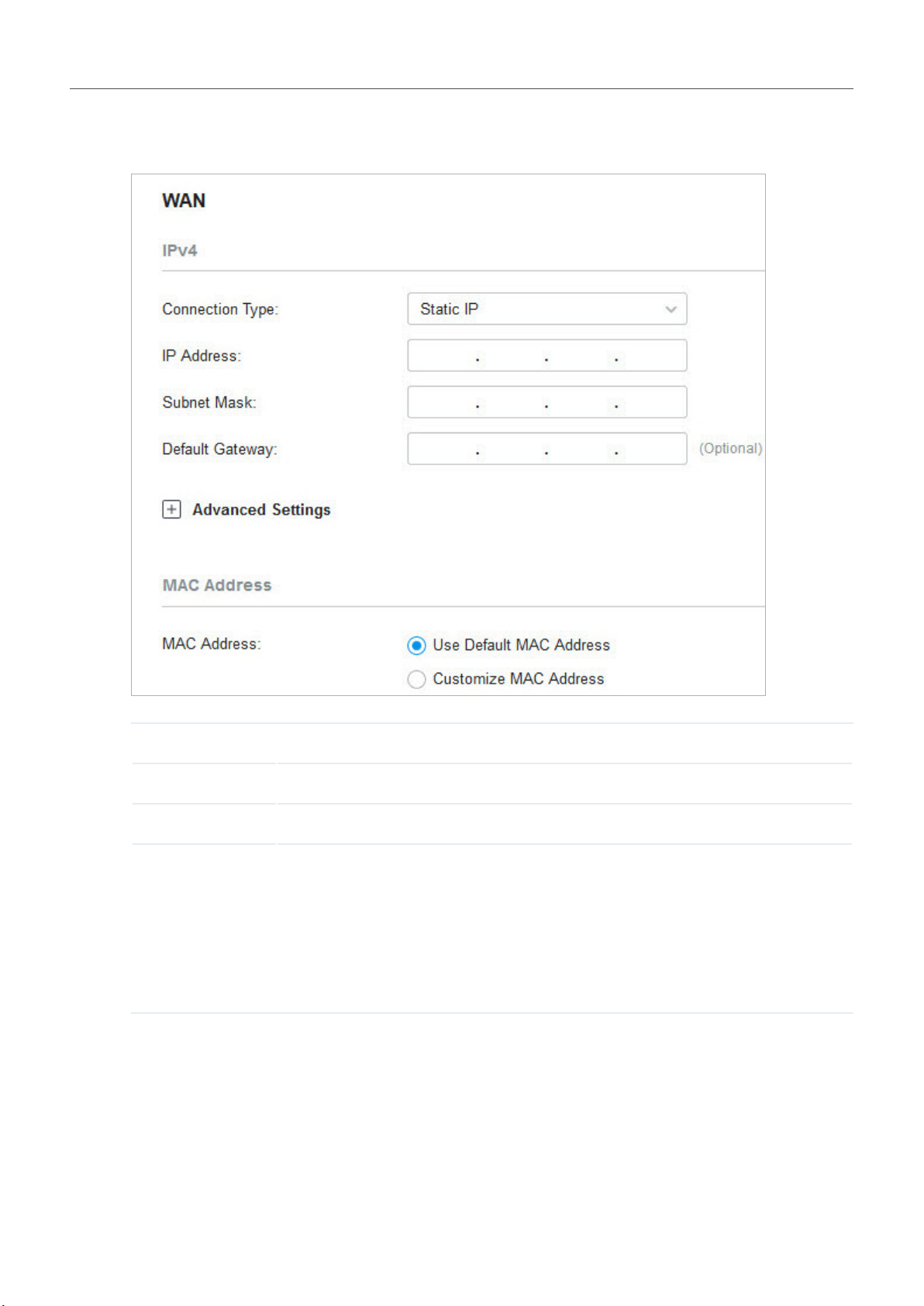
Chapter 4
ConguretheNetworkwithOmadaSDNController
■ Static IP
1. Choose Connection Type as Static IP and configure the following parameters.
IP Address Enter the IP address provided by your ISP.
Subnet Mask Enter the subnet mask provided by your ISP.
Default Gateway Enter the default gateway provided by your ISP.
MAC Address Use Default MAC Address: The WAN port uses the default MAC address to set up the
internet connection. It’s recommended to use the default MAC address unless required
otherwise.
Customize MAC Address: The WAN port uses a customized MAC address to set up
the internet connection and you need to specify the MAC address. Typically, this is
required when your ISP bound the MAC address with your account or IP address. If you
are not sure, contact the ISP.
57
Page 64

Chapter 4
ConguretheNetworkwithOmadaSDNController
2. Click + Advanced Settings and configure the following parameters. Then click Apply.
Primary DNS Server /
Secondary DNS Server
MTU Specify the MTU (Maximum Transmission Unit) of the WAN port.
VLAN Add the WAN port to a VLAN and you need to specify the VLAN. Generally, you
QoS Tag The QoS (Quality of Service) function helps to prioritize the internet traffic based
Enter the IP address of the DNS server provided by your ISP if there is any.
MTU is the maximum data unit transmitted in the physical network. When the
connection type is Static IP, MTU can be set in the range of 576-1500 bytes. The
default value is 1500.
don’t need to manually configure it unless required by your ISP.
on your needs. You can determine the priority level for the traffic by specifying
the tag. The tag ranges from 1 to 7. None means the packet will be forwarded
without any operation.
QoS Tag is only available when VLAN is enabled.
58
Page 65

Chapter 4
ConguretheNetworkwithOmadaSDNController
■ PPPoE
1. Choose Connection Type as Static IP and configure the following parameters.
Username Enter the PPPoE username provided by your ISP.
Password Enter the PPPoE password provided by your ISP.
MAC Address Use Default MAC Address: The WAN port uses the default MAC address to set up the
internet connection. It’s recommended to use the default MAC address unless required
otherwise.
Customize MAC Address: The WAN port uses a customized MAC address to set up
the internet connection and you need to specify the MAC address. Typically, this is
required when your ISP bound the MAC address with your account or IP address. If you
are not sure, contact the ISP.
59
Page 66

Chapter 4
ConguretheNetworkwithOmadaSDNController
2. Click + Advanced Settings and configure the following parameters. Then click Apply.
60
Page 67

Chapter 4
Get IP address from ISP With this option enabled, the gateway gets IP address from ISP when setting up
the WAN connection.
With this option disabled, you need to specify the IP Address provided by your
ISP.
ConguretheNetworkwithOmadaSDNController
Primary DNS Server /
Secondary DNS Server
Connection Mode Connect Automatically: The gateway activates the connection automatically
Service Name Keep it blank unless your ISP requires you to configure it.
MTU Specify the MTU (Maximum Transmission Unit) of the WAN port.
VLAN Add the WAN port to a VLAN and you need to specify the VLAN. Generally, you
QoS Tag The QoS (Quality of Service) function helps to prioritize the internet traffic based
Enter the IP address of the DNS server provided by your ISP if there is any.
when the connection is down. You need to specify the Redial Interval, which
decides how often the gateway tries to redial after the connection is down.
Connect Manually: You can manually activate or terminate the connection.
Time-Based: During the specified period, the gateway will automatically activate
the connection. You need to specify the Time Range when the connection is up.
MTU is the maximum data unit transmitted in the physical network. When the
connection type is PPPoE, MTU can be set in the range of 576-1492 bytes. The
default value is 1492.
don’t need to manually configure it unless required by your ISP.
on your needs. You can determine the priority level for the traffic by specifying
the tag. The tag ranges from 1 to 7. None means the packet will be forwarded
without any operation.
QoS Tag is only available when VLAN is enabled.
Secondary Connection Secondary connection is required by some ISPs. Select the connection type
required by your ISP.
None: Select this if the secondary connection is not required by your ISP.
Static IP: Select this if your ISP provides you with a fixed IP address and subnet
mask for the secondary connection. You need to specify the IP Address and
Subnet Mask provided by your ISP.
Dynamic IP: Select this if your ISP automatically assigns the IP address and
subnet mask for the secondary connection.
61
Page 68

Chapter 4
ConguretheNetworkwithOmadaSDNController
■ L2TP
Choose Connection Type as L2TP and configure the following parameters. Then click Apply.
Username Enter the L2TP username provided by your ISP.
Password Enter the L2TP password provided by your ISP.
62
Page 69

Chapter 4
VPN Server / Domain Name Enter the VPN Server/Domain Name provided by your ISP.
Get IP address from ISP With this option enabled, the gateway gets IP address from ISP when setting up
the WAN connection.
With this option disabled, you need to specify the IP address provided by your
ISP.
ConguretheNetworkwithOmadaSDNController
Primary DNS Server /
Secondary DNS Server
Connection Mode Connect Automatically: The gateway activates the connection automatically when
MTU Specify the MTU (Maximum Transmission Unit) of the WAN port.
VLAN Add the WAN port to a VLAN and you need to specify the VLAN. Generally, you
QoS Tag The QoS (Quality of Service) function helps to prioritize the internet traffic based
Enter the IP address of the DNS server provided by your ISP if there is any.
the connection is down. You need to specify the Redial Interval, which decides
how often the gateway tries to redial after the connection is down.
Connect Manually: You can manually activate or terminate the connection.
Time-Based: During the specified period, the gateway will automatically activate
the connection. You need to specify the Time Range when the connection is up.
MTU is the maximum data unit transmitted in the physical network. When the
connection type is L2TP, MTU can be set in the range of 576-1460 bytes. The
default value is 1460.
don’t need to manually configure it unless required by your ISP.
on your needs. You can determine the priority level for the traffic by specifying the
tag. The tag ranges from 1 to 7. None means the packet will be forwarded without
any operation.
QoS Tag is only available when VLAN is enabled.
Secondary Connection Select the connection type required by your ISP.
Static IP: Select this if your ISP provides you with a fixed IP address and subnet
mask for the secondary connection. You need to specify the IP Address, Subnet
Mask, Default Gateway (Optional), Primary DNS Server (Optional), and Secondary
DNS Server (Optional) provided by your ISP.
Dynamic IP: Select this if your ISP automatically assigns the IP address and subnet
mask for the secondary connection.
MAC Address Use Default MAC Address: The WAN port uses the default MAC address to set up
the internet connection. It’s recommended to use the default MAC address unless
required otherwise.
Customize MAC Address: The WAN port uses a customized MAC address to set
up the internet connection and you need to specify the MAC address. Typically,
this is required when your ISP bound the MAC address with your account or IP
address. If you are not sure, contact the ISP.
63
Page 70

Chapter 4
ConguretheNetworkwithOmadaSDNController
■ PPTP
Choose Connection Type as PPTP and configure the following parameters. Then click Apply.
Username Enter the PPTP username provided by your ISP.
Password Enter the PPTP password provided by your ISP.
VPN Server / Domain Name Enter the VPN Server/Domain Name provided by your ISP.
Get IP address from ISP With this option enabled, the gateway gets IP address from ISP when setting up
the WAN connection.
With this option disabled, you need to specify the IP address provided by your
ISP.
Primary DNS Server /
Secondary DNS Server
Enter the IP address of the DNS server provided by your ISP if there is any.
64
Page 71

Chapter 4
Connection Mode Connect Automatically: The gateway activates the connection automatically when
the connection is down. You need to specify the Redial Interval, which decides
how often the gateway tries to redial after the connection is down.
Connect Manually: You can manually activate or terminate the connection.
Time-Based: During the specified period, the gateway will automatically activate
the connection. You need to specify the Time Range when the connection is up.
MTU Specify the MTU (Maximum Transmission Unit) of the WAN port.
MTU is the maximum data unit transmitted in the physical network. When the
connection type is PPTP, MTU can be set in the range of 576-1420 bytes. The
default value is 1420.
VLAN Add the WAN port to a VLAN and you need to specify the VLAN. Generally, you
don’t need to manually configure it unless required by your ISP.
QoS Tag The QoS (Quality of Service) function helps to prioritize the internet traffic based
on your needs. You can determine the priority level for the traffic by specifying the
tag. The tag ranges from 1 to 7. None means the packet will be forwarded without
any operation.
ConguretheNetworkwithOmadaSDNController
QoS Tag is only available when VLAN is enabled.
Secondary Connection Select the connection type required by your ISP.
Static IP: Select this if your ISP provides you with a fixed IP address and subnet
mask for the secondary connection. You need to specify the IP Address, Subnet
Mask, Default Gateway (Optional), Primary DNS Server (Optional), and Secondary
DNS Server (Optional) provided by your ISP.
Dynamic IP: Select this if your ISP automatically assigns the IP address and subnet
mask for the secondary connection.
MAC Address Use Default MAC Address: The WAN port uses the default MAC address to set up
the internet connection. It’s recommended to use the default MAC address unless
required otherwise.
Customize MAC Address: The WAN port uses a customized MAC address to set
up the internet connection and you need to specify the MAC address. Typically,
this is required when your ISP bound the MAC address with your account or IP
address. If you are not sure, contact the ISP.
Select WAN Mode Configure WAN Connections (Optional) Configure Load Balancing
Note:
Loading Balancing is only available when you configure more than one WAN port.
65
Page 72

Chapter 4
ConguretheNetworkwithOmadaSDNController
Go to Settings > Wired Networks > Internet to load the following page. In Load Balancing, configure the
following parameters and click Apply.
Load Balancing Weight Specify the ratio of network traffic that each WAN port carries.
Alternatively, you can click Pre-Populate to test the speed of WAN ports and
automatically fill in the appropriate ratio according to test result.
Application Optimized
Routing
Link Backup With Link Backup enabled, the router will switch all the new sessions from dropped
Backup WAN / Primary WAN The backup WAN port backs up the traffic for the primary WAN ports under the
Backup Mode Link Backup: The system will switch all the new sessions from dropped line
With Application Optimized Routing enabled, the router will consider the source IP
address and destination IP address (or destination port) of the packets as a whole
and record the WAN port they pass through. Then the packets with the same source
IP address and destination IP address ( or destination port) will be forwarded to the
recorded WAN port.
This feature ensures that multi-connected applications work properly.
lines automatically to another to keep an always on-line network.
specified condition.
automatically to another to keep an always on-link network.
Always Link Primary: Traffic is always forwarded through the primary WAN port unless
it fails. The system will try to forward the traffic via the backup WAN port when it fails,
and switch back when it recovers.
Mode Select whether to enable backup link when any primary WAN fails or all primary WANs
fail.
66
Page 73

Chapter 4
ConguretheNetworkwithOmadaSDNController
4. 3. 2 Configure LAN Networks
Overview
The LAN function allows you to configure wired internal network. Based on 802.1Q VLAN, Omada
Controller provides a convenient and flexible way to separate and deploy the network. The network can
be logically segmented by departments, application, or types of users, without regard to geographic
locations.
Configuration
To create a LAN, follow the guidelines:
1 ) Create a Network with specific purpose. For Layer 2 isolation, create a network as VLAN. To realize
inter-VLAN routing, create a network as Interface, which is configured with a VLAN interface.
2 ) Create a port profile for the network. The profile defines how the packets in both ingress and egress
directions are handled.
3 ) Assign the port profile to the desired ports of the switch to activate the LAN.
Create a Network Create a Port Profile Assign the Port Profile to the Ports
Note:
A default Network (default VLAN) named LAN is preconfigured as Interface and is associated with all LAN ports of the
Omada Gateway and all switch ports. The VLAN ID of the default Network is 1. The default Network can be edited, but not
deleted.
1. Go to Settings > Wired Networks > LAN > Networks to load the following page.
2. Click + Create New LAN to load the following page, enter a name to identify the network, and select
the purpose for the network.
67
Page 74

Chapter 4
Purpose Interface: Create the network with a Layer 3 interface, which is required for inter-VLAN
routing.
VLAN: Create the network as a Layer 2 VLAN.
ConguretheNetworkwithOmadaSDNController
3. Configure the parameters according to the purpose for the network.
■ Interface
LAN Interface Select the physical interfaces of the Omada Gateway that this network will be
associated with.
68
Page 75

Chapter 4
VLAN Enter a VLAN ID with the values between 1 and 4090. Each VLAN can be uniquely
identified by VLAN ID, which is transmitted and received as IEEE 802.1Q tag in an
Ethernet frame.
Gateway/Subnet Enter the IP address and subnet mask in the CIDR format. The CIDR Notation here
includes the IP address and subnet mask of the default gateway. The summary of the
information that you entered will show up below in realtime.
Domain Name Enter the domain name.
IGMP Snooping Click the checkbox to monitor IGMP (Internet Group Management Protocol) traffic and
thereby manage multicast traffic.
DHCP Server Click the checkbox to allow the Omada Gateway to serve as the DHCP server for this
network. A DHCP server assigns IP addresses, DNS server, default gateway, and other
parameters to all devices in the network. Uncheck the box if there is already a DHCP
server in the network.
DHCP Range Enter the starting and ending IP addresses of the DHCP address pool in the fields
provided. For quick operation, click the Update DHCP Range beside the Gateway/
Subnet entry to get the IP address range populated automatically, and edit the range
according to your needs.
ConguretheNetworkwithOmadaSDNController
DNS Server Select a method to configure the DNS server for the network.
Auto: The DHCP server automatically assigns DNS server for devices in the network. It
uses the IP address specified in the Gateway/Subnet entry as the DNS server address.
Manual: Specify DNS servers manually. Enter the IP address of a server in each DNS
server field.
Lease TIme Specify how long a client can use the IP address assigned from this address pool.
Default Gateway Enter the IP address of the default gateway.
Auto: The DHCP server automatically assigns default gateway for devices in the
network. It uses the IP address specified in the Gateway/Subnet entry as the default
gateway address.
Manual: Specify default gateway manually. Enter the IP address of the default gateway
in the field.
DHCP Omada
Controller
Legal DHCP Servers Click the checkbox to specify legal DHCP servers for the network. With legal DHCP
Enter the IP address of the Omada Controller. The DHCP server uses this IP address as
Option 138 in DHCP packets to tell clients where the controller is.
servers configured, Omada Gateways and Switches ensure that clients get IP
addresses only from the DHCP servers specified here.
Option 60 Enter the value for DHCP Option 60. DHCP clients use this field to optionally identify
the vendor type and configuration of a DHCP client. Mostly it is used in the scenario
where the APs apply for different IP addresses from different servers according to the
needs.
Option 66 Enter the value for DHCP Option 66. It specifies the TFTP server information and
supports a single TFTP server IP address.
69
Page 76
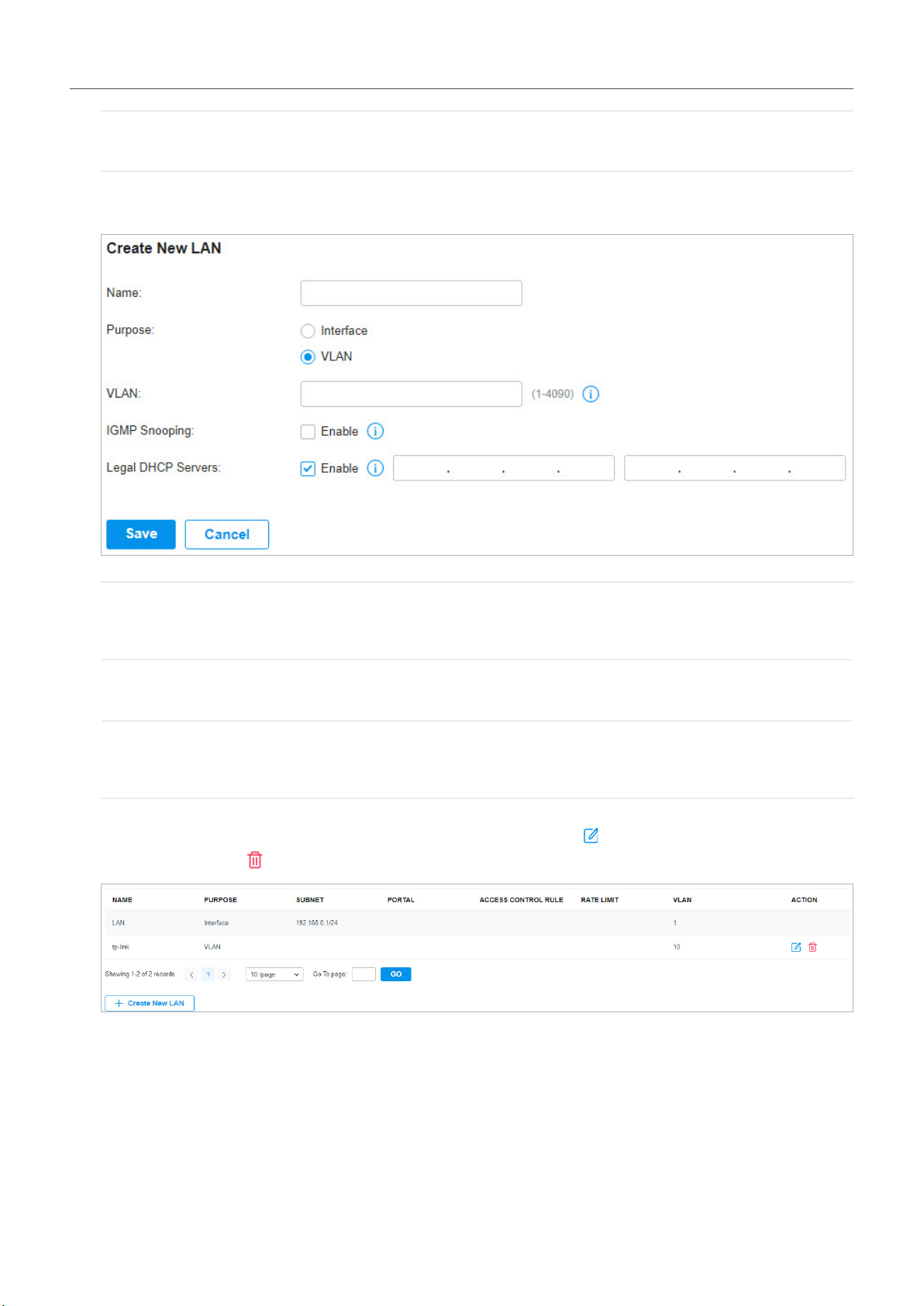
Chapter 4
Option 138 Enter the value for DHCP Option 138. It is used in discovering the devices by the
Omada controller.
ConguretheNetworkwithOmadaSDNController
■ VLAN
VLAN Enter a VLAN ID with the values between 1 and 4090. Each VLAN can be uniquely
identified by VLAN ID, which is transmitted and received as IEEE 802.1Q tag in an
Ethernet frame.
IGMP Snooping Click the checkbox to monitor IGMP (Internet Group Management Protocol) traffic and
thereby manage multicast traffic.
Legal DHCP Servers Click the checkbox to specify legal DHCP servers for the network. With legal DHCP
servers configured, Omada Gateways and Switches ensure that clients get IP
addresses only from the DHCP servers specified here.
4. Click Save. The new LAN is added to the LAN list. You can click in the ACTION column to edit the
LAN. You can click in the ACTION column to delete the LAN.
70
Page 77
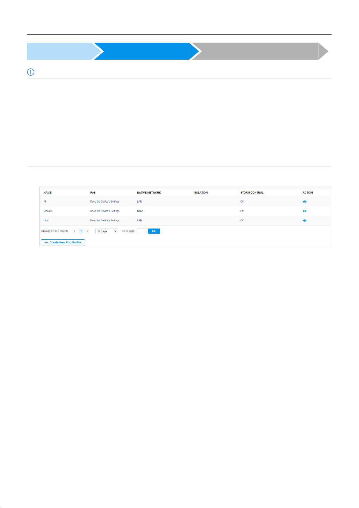
Chapter 4
ConguretheNetworkwithOmadaSDNController
Create a Network Create a Port Profile Assign the Port Profile to the Ports
Note:
• Three default port profiles are preconfigured on the controller. They can be viewed, but not edited or deleted.
All: In the All profile, all networks except the default network (LAN) are configured as Tagged Network, and the native network is
the default network (LAN). This profile is assigned to all switch ports by default.
Disable: In the Disable profile, no networks are configured as the native network, Tagged Networks and Untagged Networks.
With this profile assigned to a port, the port does not belong to any VLAN.
LAN: In the LAN profile, the native network is the default network (LAN), and no networks are configured as Tagged Networks
and Untagged Networks.
• When a network is created, the system will automatically create a profile with the same name and configure the network as
the native network for the profile. In this profile, no networks are configured as Tagged Networks and Untagged Networks. The
profile can be viewed, but not edited or deleted.
1. Go to Wired Networks > LAN > Profiles to load the following page.
71
Page 78
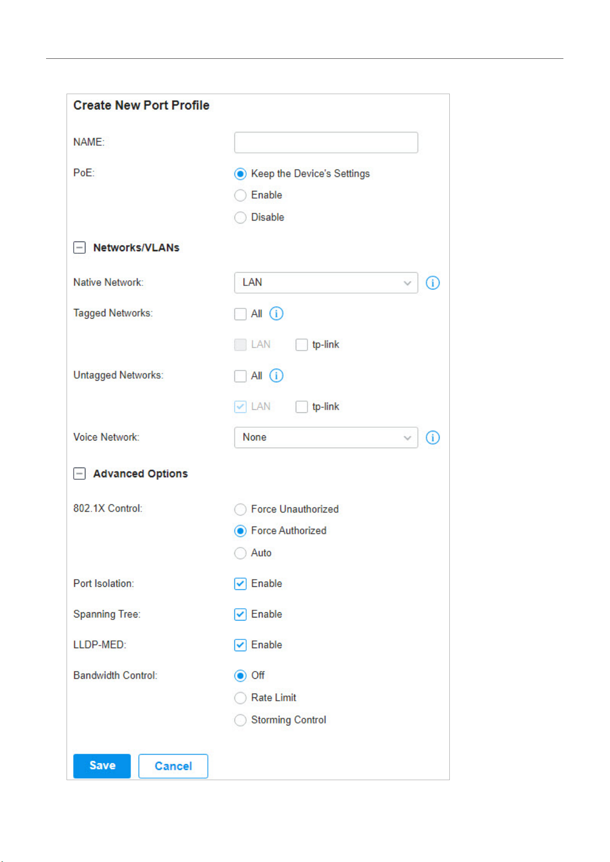
Chapter 4
ConguretheNetworkwithOmadaSDNController
2. Click + Create New Port Profile to load the following page, and configure the following parameters.
72
Page 79

Chapter 4
Name Enter a name to identify the port profile.
PoE Select the PoE mode for the ports.
Keep the Device's Settings: PoE keep enabled or disabled according to the switches’
settings. By default, the switches enable PoE on all PoE ports.
Enable: Enable PoE on PoE ports.
Disable: Disable PoE on PoE ports.
Native Network Select the native network from all networks. The native network determines the Port
VLAN Identifier (PVID) for switch ports. When a port receives an untagged frame, the
switch inserts a VLAN tag to the frame based on the PVID, and forwards the frame in
the native network. Each physical switch port can have multiple networks attached, but
only one of them can be native.
Tagged Networks Select the Tagged Networks. Frames sent out of a Tagged Network are kept with
VLAN tags. Usually networks that connect the switch to network devices like routers
and other swithes, or VoIP devices like IP phones should be configured as Tagged
Networks.
ConguretheNetworkwithOmadaSDNController
Untagged Networks Select the Untagged Networks. Frames that sent out of an Untagged Network are
stripped of VLAN tags. Usually networks that connect the switch to endpoint devices
like computers should be configured as Untagged Networks. Note that the native
network is untagged.
Voice Network Select the network that connects VoIP devices like IP phones as the Voice Network.
Omada Switches will prioritize the voice traffic by changing its 802.1p priority. To
configure a network as Voice Network, configure it as Tagged Network first, and then
enable LLDP-MED. Only tagged networks can be configured as Voice Network, and
Voice Network will take effect with LLDP-MED enabled.
802.1X Control Select 802.1X Control mode for the ports. To configure the 802.1X authentication
globally, go to Settings > Authentication > 802.1X.
Auto: The port is unauthorized until the client is authenticated by the authentication
server successfully.
Force Authorized: The port remains in the authorized state, sends and receives normal
traffic without 802.1X authentication of the client.
Force Unauthorized: The port remains in the unauthorized state, ignoring all attempts
by the client to authenticate. The switch cannot provide authentication services to the
client through the port.
Port Isolation Click the checkbox to enable Port Isolation. An isolated port cannot communicate
directly with any other isolated ports, while the isolated port can send and receive
traffic to non-isolated ports.
Spanning Tree Click the checkbox to enable Spanning Tree. It helps to ensure that you do not create
loops when you have redundant paths in the network.
If you want to enable Spanning Tree for the switch, you also need to select the
Spanning Tree protocol in the Device Config page. For details, refer to Configure and
Monitor Switches.
73
Page 80
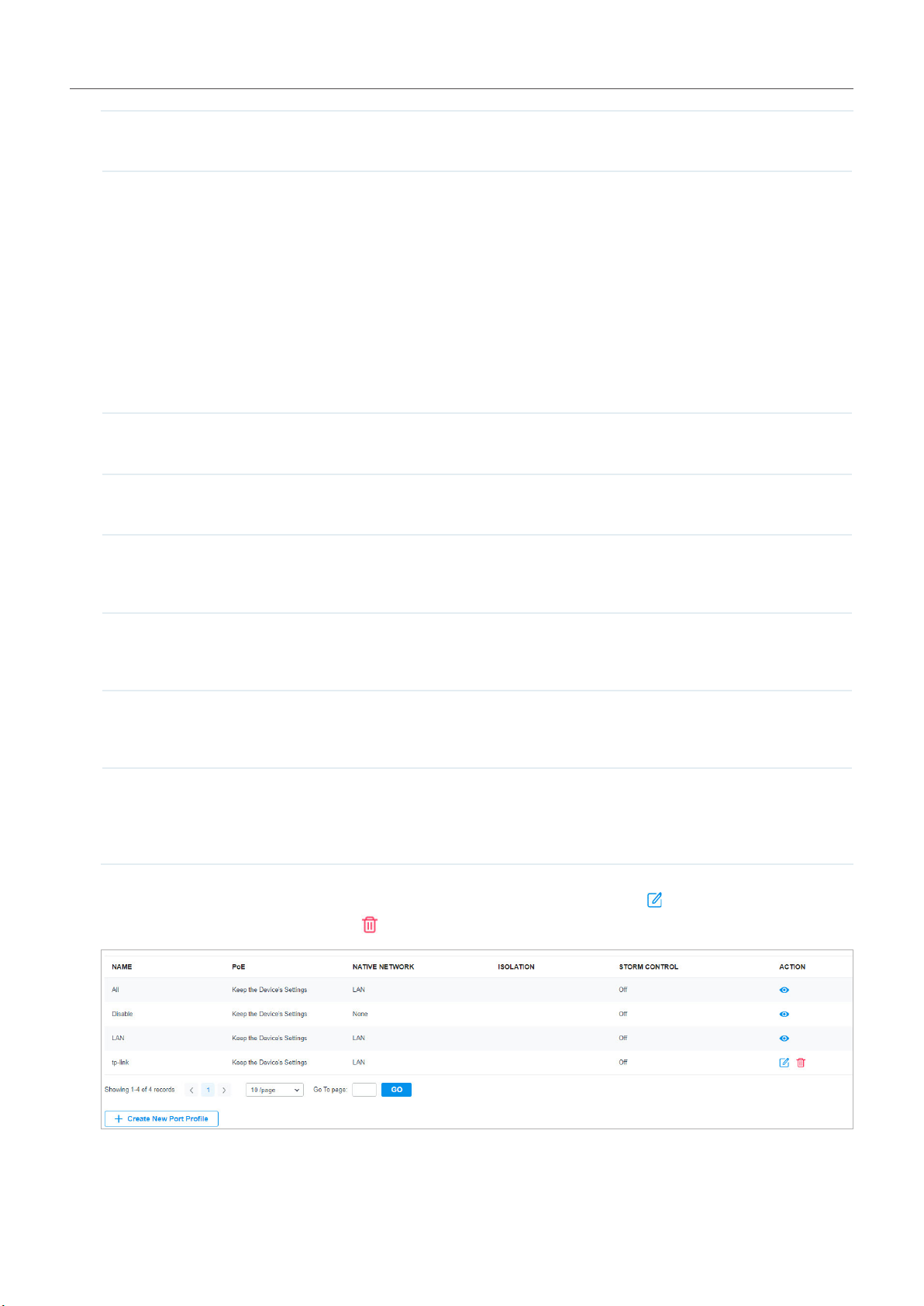
Chapter 4
LLDP-MED Click the checkbox to enable LLDP-MED (Link Layer Discovery Protocol-Media
Endpoint Discovery) for device discovery and auto-configuration of VoIP devices.
Bandwidth Control Select the type of Bandwidth Control functions to control the traffic rate and traffic
threshold on each port to ensure network performance.
Off: Disable Bandwidth Control for the port.
Rate Limit: Select Rate limit to limit the ingress/egress traffic rate on each port. With
this function, the network bandwidth can be reasonably distributed and utilized.
Storm Control: Select Storm Control to allow the switch to monitor broadcast frames,
multicast frames and UL-frames (Unknown unicast frames) in the network. If the
transmission rate of the frames exceeds the set rate, the frames will be automatically
discarded to avoid network broadcast storm.
Ingress Rate Limit When Rate Limit selected, click the checkbox and specify the upper rate limit for
receiving packets on the port.
Egress Rate Limit When Rate Limit selected, click the checkbox and specify the upper rate limit for
sending packets on the port.
ConguretheNetworkwithOmadaSDNController
Broadcast Threshold When Storm Control selected, click the checkbox and specify the upper rate limit for
receiving broadcast frames. The broadcast traffic exceeding the limit will be processed
according to the Action configurations.
Multicast Threshold When Storm Control selected, click the checkbox and specify the upper rate limit for
receiving multicast frames. The multicast traffic exceeding the limit will be processed
according to the Action configurations.
UL-Frame Threshold When Storm Control selected, click the checkbox and specify the upper rate limit for
receiving unknown unicast frames. The traffic exceeding the limit will be processed
according to the Action configurations..
Action When Storm Control selected, select the action that the switch will take when the traffic
exceeds its corresponding limit. With Drop selected, the port will drop the subsequent
frames when the traffic exceeds the limit. With Shutdown selected, the port will be
shutdown when the traffic exceeds the limit.
3. Click Save. The new port profile is added to the profile list. You can click in the ACTION column to
edit the port profile. You can click in the ACTION column to delete the port profile.
74
Page 81

Chapter 4
Create a Network Create a Port Profile Assign the Port Profile to the Ports
ConguretheNetworkwithOmadaSDNController
Note:
By default, there is a port profile named All, which is assigned to all switch ports by default. In the All profile, all networks except the
default network (LAN) are configured as Tagged Network, and the native network is the default network (LAN).
1. Go to Settings > Wired Networks > LAN > Networks, and click beside the switch in the devices
list to reveal the Properties window. Go to Ports, you can either click in the Action column to
assign the port profile to a single port, or select the desired ports and click Edit Selected on the top
to assign the port profile to multiple ports in batch.
2. Select the profile from the drop-down list to assign the port profile to the desired ports of the switch.
You can enable profile overrides to customize the settings for the ports, and all the configuration
here overrides the port profile. For details, refer to Configure and Monitor Omada Managed Devices.
75
Page 82

Chapter 4
ConguretheNetworkwithOmadaSDNController
4. 4 Configure Wireless Networks
Wireless networks enable your wireless clients to access the internet. Once you set up a wireless
network, your EAPs typically broadcast the network name (SSID) in the air, through which your wireless
clients connect to the wireless network and access the internet.
A WLAN group is a combination of wireless networks. Configure each group so that you can flexibly
apply these groups of wireless networks to different EAPs according to your needs.
After setting up basic wireless networks, you can further configure WLAN Schedule, 802.11 Rate
Control, and MAC Filter among other advanced settings.
4. 4. 1 Set Up Basic Wireless Networks
Configuration
To create, configure and apply wireless networks, follow these steps:
1 ) Create a WLAN group.
2 ) Create Wireless Networks
3 ) Apply the WLAN group to your EAPs
Create a WLAN Group Create Wireless Networks Apply the WLAN Group
Note:
By default, there is a WLAN group named Default, which is applied to all EAPs. If you simply want to configure wireless networks for the
default WLAN group and apply it to all your EAPs, skip this step.
1. Go to Settings > Wireless Networks to load the following page.
2. Select + Create New Group from the drop-down list of WLAN Group to load the following page.
Enter a name to identify the WLAN group.
76
Page 83
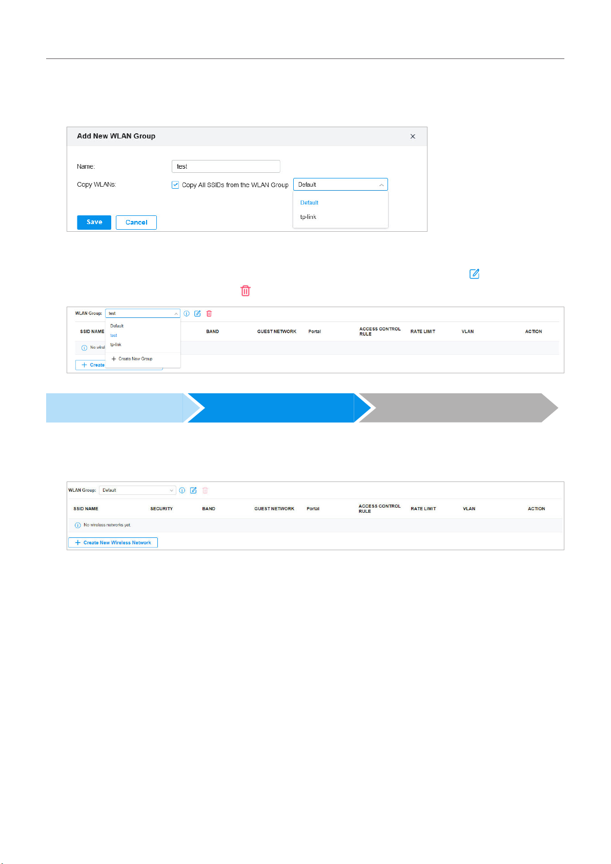
Chapter 4
ConguretheNetworkwithOmadaSDNController
3. (Optional) If you want to create a new WLAN group based on an existing one, check Copy All SSIDs
from the WLAN Group and select the desired WLAN group. Then you can further configure wireless
networks based on current settings.
4. Click Save. The new WLAN Group is added to the WLAN Group list. You can select a WLAN Group
from the list to further create and configure its wireless networks. You can click to edit the name
of the WLAN Group. You can click to delete the WLAN Group.
Create a WLAN Group Create Wireless Networks Apply the WLAN Group
1. Select the WLAN group for which you want to configure wireless networks from the drop-down list
of WLAN Group.
77
Page 84

Chapter 4
ConguretheNetworkwithOmadaSDNController
2. Click + Create New Wireless Network to load the following page. Configure the basic parameters
for the network.
Network Name (SSID) Enter the network name (SSID) to identify the wireless network. The users of wireless
clients choose to connect to the wireless network according to the SSID, which
appears on the WLAN settings page of wireless clients.
Band Enable 2.4 GHz and/or 5 GHz radio band for the wireless network.
Guest Network With Guest Network enabled, all the clients connecting to the SSID are blocked from
reaching any private IP subnet.
3. Select the security strategy for the wireless network.
■ None
With None selected, the hosts can access the wireless network without authentication, which is
applicable to lower security requirements.
78
Page 85

Chapter 4
ConguretheNetworkwithOmadaSDNController
■ WEP
Traffic is encrypted with a WEP Key, which you need to specify. WEP is not recommended because
it’s insecure.
■ WPA-Personal
Traffic is encrypted with a Security Key, which you need to specify. WPA-Personal is more secure
than WEP.
■ WPA-Enterprise
WPA-Enterprise requires an authentication server to authenticate wireless clients, and probably an
accounting server to record the traffic statistics.
79
Page 86

Chapter 4
ConguretheNetworkwithOmadaSDNController
Select a RADIUS Profile, which records the settings of the authentication server and accounting
server. You can create a RADIUS Profile by clicking + Create New Radius Profile from the drop-down
list of RADIUS Profile. For details, refer to Authentication.
4. (Optional) You can also configure Advanced Settings, WLAN Schedule, 802.11 Rate Control, and
MAC Filter according to your needs. Related topics are covered later in this chapter.
5. Click Apply. The new wireless network is added to the wireless network list under the WLAN group.
You can click in the ACTION column to edit the wireless network. You can click in the ACTION
column to delete the wireless network.
Create a WLAN Group Create Wireless Networks Apply the WLAN Group
Note:
By default, there is a WLAN group named Default, which is applied to all EAPs. If you simply want to configure wireless networks for the
default WLAN group and apply it to all your EAPs, skip this step.
80
Page 87

Chapter 4
ConguretheNetworkwithOmadaSDNController
■ Apply to a Single EAP
Go to Devices, select the EAP which you want to apply the WLAN group to. In the Properties window,
go to Config > WLANs, select the WLAN group which you want to apply to the EAP.
■ Apply to EAPs in batch
1. Go to Devices, select the APs tab, click , select Batch Config, check the boxes of EAPs which you
want to apply the WLAN group to, and click Edit Selected.
2. In the Properties window, go to Config > WLANs, select the WLAN group which you want to apply
to the EAP.
81
Page 88

Chapter 4
ConguretheNetworkwithOmadaSDNController
4. 4. 2 Advanced Settings
Go to Settings > Wireless Networks, click in the ACTION column of the wireless network which you
want to configure, and click + Advanced Settings to load the following page. Configure the parameters
and click Apply.
SSID Broadcast With SSID Broadcast enabled, EAPs broadcast the SSID (network name) in the air so that
wireless clients can connect to the wireless network, which is identified by the SSID.
With SSID Broadcast disabled, users of wireless clients must enter the SSID manually to
connect to the wireless network.
VLAN To set a wireless VLAN for the wireless network, enable this option and set a VLAN ID
from 1 to 4094.
With this option enabled, traffic in different wireless networks is marked with different
VLAN tags according to the configured VLAN IDs. Then the EAPs work together with the
switches which also support 802.1Q VLAN, to distribute the traffic to different VLANs
according to the VLAN tags. As a result, wireless clients in different VLANs cannot
directly communicate with each other.
82
Page 89

Chapter 4
WEP Mode If you select WEP as the security strategy, you can select the WEP Mode including the
WEP authentication type, the WEP key format, and the WEP key length.
Select the WEP authentication type.
Open System: Wireless clients can pass the authentication and connect to the wireless
network without any password. However, the correct password is required for data
transmission.
Shared Key: The correct password is required for wireless clients to pass the
authentication, connect to the wireless network, and transmit data.
Auto: EAPs automatically decide whether to use Open System or Shared Key in the
authentication process.
Select the WEP key format.
ASCII: ASCII format stands for any combination of keyboard characters of the specified
length.
Hexadecimal: Hexadecimal format stands for any combination of hexadecimal digits (0-9,
A-F) with the specified length.
ConguretheNetworkwithOmadaSDNController
Select the WEP key length.
64Bit: The WEP key is 10 hexadecimal digits or 5 ASCII characters.
128Bit: The WEP key is 26 hexadecimal digits or 13 ASCII characters.
152Bit: The WEP key is 32 hexadecimal digits or 16 ASCII characters.
WPA Mode If you select WPA-Personal or WPA-Enterprise as the security strategy, you can select
the WPA Mode including the version of WPA, and the encryption type.
Select the version of WPA according to your needs.
Select the encryption type. Some encryption type is only available under certain
circumstances.
TKIP: TKIP stands for Temporal Key Integrity Protocol.
AES: AES stands for Advanced Encryption Standard. We recommend that you select
AES as the encryption type for it is more secure than TKIP.
Auto: EAPs automatically decide whether to use TKIP or AES in the authentication
process.
Group Key Update Period If you select WPA-Personal or WPA-Enterprise as the security strategy, you can specify
whether and how often the security key changes. If you want the security key to change
periodically, enable GIK rekeying and specify the time period.
Rate Limit You can limit the download and upload rate of each client to balance bandwidth usage.
Download Limit: Set the download rate for each client to receive the traffic.
Upload Limit: Set the upload rate for each client to transmit the traffic.
83
Page 90

Chapter 4
ConguretheNetworkwithOmadaSDNController
4. 4. 3 WLAN Schedule
Overview
WLAN Schedule can turn on or off your wireless network in the specific time period as you desire.
Configuration
Go to Settings > Wireless Networks, click in the ACTION column of the wireless network which you
want to configure, and click + WLAN Schedule to load the following page. Enable WLAN schedule and
configure the parameters .Then click Apply.
Action Radio On: Turn on your wireless network within the time range you set, and turn it off
beyond the time range.
Radio Off: Turn off your wireless network within the time range you set, and turn it on
beyond the time range.
Time Range Select the Time Range for the action to take effect. You can create a Time Range entry
by clicking + Create New Time Range Entry from the drop-down list of Time Range. For
details, refer to Create Profiles.
4. 4. 4 802.11 Rate Control
Overview
Note:
802.11 Rate Control is only available for certain devices.
802.11 Rate Control can improve performance for higher-density networks by disabling lower bit
rates and only allowing the higher. However, 802.11 Rate Control might make some legacy devices
incompatible with your networks, and limit the range of your wireless networks.
Configuration
Go to Settings > Wireless Networks, click in the ACTION column of the wireless network which you
want to configure, and click + 802.11 Rate Control to load the following page. Select 2.4 GHz and/or 5
84
Page 91

Chapter 4
ConguretheNetworkwithOmadaSDNController
GHz band to enable minimum data rate control according to your needs, move the slider to determine
what bit rates your wireless network allows, and configure the parameters. Then click Apply.
Disable CCK Rates (1/2/5.5/11 Mbps) Select whether to disable CCK (Complementary Code Keying), the modulation
scheme which works with 802.11b devices. Disable CCK Rates (1/2/5.5/11
Mbps) is only available for 2.4 GHz band.
Require Clients to Use Rates at or
Above the Specified Value
Send Beacons at 1 Mbps/6 Mbps Select whether or not to send Beacons at the minimum rate of 1Mbps for 2.4
Select whether or not to require clients to use rates at or above the value that
the slider indicates.
GHz band or 6Mbps for 5 GHz band.
4. 4. 5 MAC Filter
Overview
MAC Filter allows or blocks connections from wireless clients of specific MAC addresses.
85
Page 92

Chapter 4
ConguretheNetworkwithOmadaSDNController
Configuration
Go to Settings > Wireless Networks, click in the ACTION column of the wireless network which you
want to configure, and click + MAC Filter to load the following page. Enable MAC Filter and configure the
parameters .Then click Apply.
Policy Whitelist: Allow the connection of the clients whose MAC addresses are in the specified MAC
Address List, while blocking others.
Blacklist: Block the connection of the clients whose MAC address are in the specified MAC
Addresses List, while allowing others.
MAC Address List Select the MAC Group which you want to allow or block according to the policy. You can create
new MAC group by clicking + Create New MAC Group from the drop-down list of MAC Address
List. For details, refer to Create Profiles.
86
Page 93

Chapter 4
ConguretheNetworkwithOmadaSDNController
4. 5 Network Security
Network Security is a portfolio of features designed to improve the usability and ensure the safety
of your network and data. Network security services include ACL, URL Filtering, and Attack Defense,
which implement policies and controls on multiple layers of defenses in the network.
4. 5. 1 ACL
Overview
ACL (Access Control List) allows a network administrator to create rules to restrict access to network
resources. ACL rules filter traffic based on specified criteria such as source IP addresses, destination
IP addresses, and port numbers, and determine whether to forward the matched packets. These rules
can be applied to specific clients or groups whose traffic passes through the gateway, switches and
EAPs.
The system filters traffic against the rules in the list sequentially. The first match determines whether
the packet is accepted or dropped, and other rules are not checked after the first match. Therefore, the
order of the rules is critical. By default, the rules are prioritized by their created time. The rule created
earlier is checked for a match with higher priority. To reorder the rules, select a rule and drag it to a new
position. If no rules match, the device forwards the packet because of an implicit Permit All clause.
The system provides three types of ACL:
■ Gateway ACL
After Gateway ACLs are configured on the controller, they can be applied to the gateway to control
traffic which is sourced from LAN ports and forwarded to the WAN ports.
You can set the Network, IP address, port number of a packet as packet-filtering criteria in the rule.
■ Switch ACL
After Switch ACLs are configured on the controller, they can be applied to the switch to control
inbound and outbound traffic through switch ports.
You can set the Network, IP address, port number and MAC address of a packet as packet-filtering
criteria in the rule.
■ EAP ACL
After EAP ACLs are configured on the controller, they can be applied to the EAPs to control traffic
in wireless networks.
You can set the Network, IP address, port number and SSID of a packet as packet-filtering criteria
in the rule.
Configuration
To complete the ACL configuration, follow these steps:
1 ) Create an ACL with the specified type.
87
Page 94
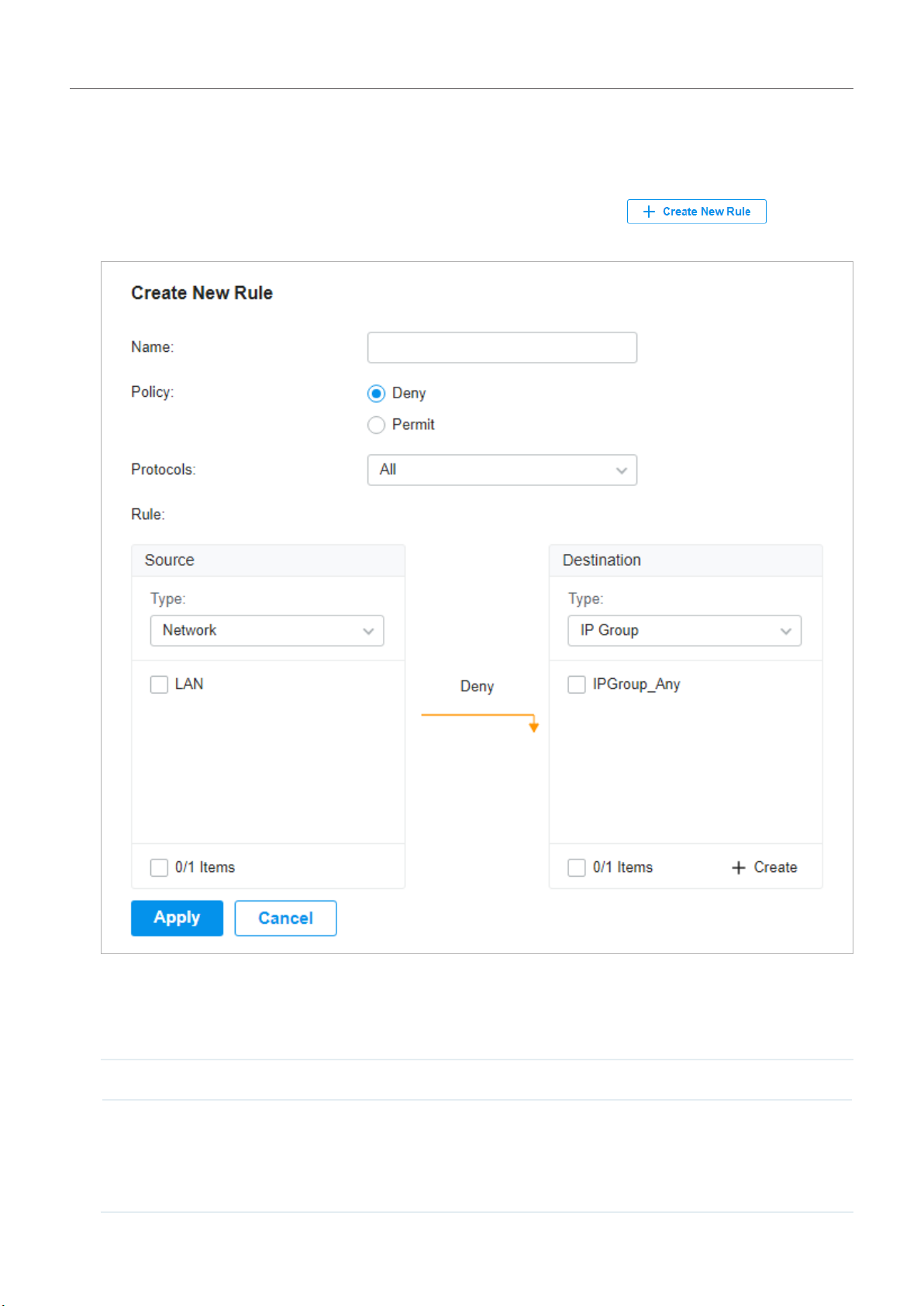
Chapter 4
ConguretheNetworkwithOmadaSDNController
2 ) Define packet-filtering criteria of the rule, including protocols, source, and destination, and
determine whether to forward the matched packets.
■ Configuring Gateway ACL
1. Go to Settings > Network Security > ACL. On Gateway ACL tab, click to load the
following page.
2. Define packet-filtering criteria of the rule, including protocols, source, and destination, and
determine whether to forward the matched packets. Refer to the following table to configure the
required parameters and click Apply.
Name Enter a name to identify the ACL.
Policy Select the action to be taken when a packet matches the rule.
Permit: Forward the matched packet.
Deny: Discard the matched packet.
88
Page 95

Chapter 4
Protocols Select one or more protocol types to which the rule applies from the drop-down
list. The default is All, indicating that packets of all protocols will be matched. When
you select one of TCP and UDP or both of them, you can set the IP address and port
number of a packet as packet-filtering criteria in the rule.
ConguretheNetworkwithOmadaSDNController
From the Source drop-down list, choose one of these options to specify the source of the packets
to which this ACL applies:
Network Select the network you have created. If no networks have been created, you can select
the default network (LAN), or go to Settings > Wired Networks > LAN to create one.
The gateway will examine whether the packets are sourced from the selected network.
IP Group Select the IP Group you have created. If no IP Groups have been created, click +Create
on this page or go to Settings > Profiles > Groups to create one. The gateway will
examine whether the source IP address of the packet is in the IP Group.
IP-Port Group Select the IP-Port Group you have created. If no IP-Port Groups have been created,
click +Create on this page or go to Settings > Profiles > Groups to create one. The
gateway will examine whether the source IP address and port number of the packet
are in the IP-Port Group.
From the Destination drop-down list, choose one of these options to specify the destination of the
packets to which this ACL applies:
IP Group Select the IP Group you have created. If no IP Groups have been created, click +Create
on this page or go to Settings > Profiles > Groups to create one. The gateway will
examine whether the destination IP address of the packet is in the IP Group.
IP-Port Group Select the IP-Port Group you have created. If no IP-Port Groups have been created,
click +Create on this page or go to Settings > Profiles > Groups to create one. The
gateway will examine whether the destination IP address and port number of the
packet are in the IP-Port Group.
89
Page 96

Chapter 4
ConguretheNetworkwithOmadaSDNController
■ Configuring Switch ACL
1. Go to Settings > Network Security > ACL. Under the Switch ACL tab, click to load
the following page.
90
Page 97

Chapter 4
ConguretheNetworkwithOmadaSDNController
2. Define packet-filtering criteria of the rule, including protocols, source, and destination, and
determine whether to forward the matched packets. Refer to the following table to configure the
required parameters.
Name Enter a name to identify the ACL.
Status Click the checkbox to enable the ACL.
Policy Select the action to be taken when a packet matches the rule.
Permit: Forward the matched packet.
Deny: Discard the matched packet.
Protocols Select one or more protocol types to which the rule applies from the drop-down
list. The default is All, indicating that packets of all protocols will be matched. When
you select one of TCP and UDP or both of them, you can set the IP address and port
number of a packet as packet-filtering criteria in the rule.
Bi-Directional Click the checkbox to enable the switch to create another symmetric ACL with the
name “xxx_reverse”, where “xxx” is the name of the current ACL. The two ACLs target
at packets with the opposite direction of each other.
From the Source drop-down list, choose one of these options to specify the source of the packets
to which this ACL applies:
Network Select the network you have created. If no networks have been created, you can select
the default network (LAN), or go to Settings > Wired Networks > LAN to create one.
The switch will examine whether the packets are sourced from the selected network.
IP Group Select the IP Group you have created. If no IP Groups have been created, click +Create
on this page or go to Settings > Profiles > Groups to create one. The switch will
examine whether the source IP address of the packet is in the IP Group.
IP-Port Group Select the IP-Port Group you have created. If no IP-Port Groups have been created,
click +Create on this page or go to Settings > Profiles > Groups to create one. The
switch will examine whether the source IP address and port number of the packet are
in the IP-Port Group.
MAC Group Select the MAC Group you have created. If no MAC Groups have been created, click
+Create on this page or go to Settings > Profiles > Groups to create one. The switch
will examine whether the source MAC address of the packet is in the MAC Group.
From the Destination drop-down list, choose one of these options to specify the destination of the
packets to which this ACL applies:
Network Select the network you have created. If no networks have been created, you can select
the default network (LAN), or go to Settings > Wired Networks > LAN to create one.
The switch will examine whether the packets are forwarded to the selected network.
IP Group Select the IP Group you have created. If no IP Groups have been created, click +Create
on this page or go to Settings > Profiles > Groups to create one. The switch will
examine whether the destination IP address of the packet is in the IP Group.
91
Page 98

Chapter 4
IP-Port Group Select the IP-Port Group you have created. If no IP-Port Groups have been created,
click +Create on this page or go to Settings > Profiles > Groups to create one. The
switch will examine whether the destination IP address and port number of the packet
are in the IP-Port Group.
MAC Group Select the MAC Group you have created. If no MAC Groups have been created, click
+Create on this page or go to Settings > Profiles > Groups to create one. The switch
will examine whether the destination MAC address of the packet is in the MAC Group.
ConguretheNetworkwithOmadaSDNController
3. Bind the switch ACL to a switch port or a VLAN and click Apply. Note that a switch ACL takes effect
only after it is bound to a port or VLAN.
Binding Type Specify whether to bind the ACL to ports or a VLAN.
Ports: Select All ports or Custom ports as the interfaces to be bound with the ACL. With All
ports selected, the rule is applied to all ports of the switch. With Custom ports selected, the rule
is applied to the selected ports of the switch. Click the ports from the Device List to select the
binding ports.
VLAN: Select a VLAN from the drop-down list as the interface to be bound with the ACL. If no
VLANs have been created, you can select the default VLAN 1 (LAN), or go to Settings > Wired
Networks > LAN to create one.
92
Page 99

Chapter 4
ConguretheNetworkwithOmadaSDNController
■ Configuring EAP ACL
1. Go to Settings > Network Security > ACL. Under the EAP ACL tab, click to load
the following page.
2. Define packet-filtering criteria of the rule, including protocols, source, and destination, and
determine whether to forward the matched packets. Refer to the following table to configure the
required parameters and click Apply.
Name Enter a name to identify the ACL.
Status Click the checkbox to enable the ACL.
93
Page 100

Chapter 4
Policy Select the action to be taken when a packet matches the rule.
Permit: Forward the matched packet.
Deny: Discard the matched packet.
Protocols Select one or more protocol types to which the rule applies from the drop-down
list. The default is All, indicating that packets of all protocols will be matched. When
you select one of TCP and UDP or both of them, you can set the IP address and port
number of a packet as packet-filtering criteria in the rule.
ConguretheNetworkwithOmadaSDNController
From the Source drop-down list, choose one of these options to specify the source of the packets
to which this ACL applies:
Network Select the network you have created. If no networks have been created, you can select
the default network (LAN), or go to Settings > Wired Networks > LAN to create one.
The EAP will examine whether the packets are sourced from the selected network.
IP Group Select the IP Group you have created. If no IP Groups have been created, click +Create
on this page or go to Settings > Profiles > Groups to create one. The EAP will examine
whether the source IP address of the packet is in the IP Group.
IP-Port Group Select the IP-Port Group you have created. If no IP-Port Groups have been created,
click +Create on this page or go to Settings > Profiles > Groups to create one. The EAP
will examine whether the source IP address and port number of the packet are in the
IP-Port Group.
SSID Select the SSID you have created. If no SSIDs have been created, go to Settings >
Wireless Networks to create one. The EAP will examine whether the SSID of the packet
is the SSID selected here.
From the Destination drop-down list, choose one of these options to specify the destination of the
packets to which this ACL applies:
Network Select the network you have created. If no networks have been created, you can select
the default network (LAN), or go to Settings > Wired Networks > LAN to create one.
The EAP will examine whether the packets are forwarded to the selected network.
IP Group Select the IP Group you have created. If no IP Groups have been created, click +Create
on this page or go to Settings > Profiles > Groups to create one. The EAP will examine
whether the destination IP address of the packet is in the IP Group.
IP-Port Group Select the IP-Port Group you have created. If no IP-Port Groups have been created,
click +Create on this page or go to Settings > Profiles > Groups to create one. The EAP
will examine whether the destination IP address and port number of the packet are in
the IP-Port Group.
94
 Loading...