


Uninterruptible Power System (UPS)
1600XP SERIES
Installation and Operation MANUAL
Single Phase - 3.6/6/8/10/14/18/22 kVA
Part # 60616-005
April 2011
Manufactured in the USA
© Copyright 2011 TOSHIBA International Corporation All rights reserved.

1600XP Series Installation and Operation Manual

Uninterruptible Power System (UPS)
1600XP SERIES
Installation and Operation MANUAL
Single Phase - 3.6/6/8/10/14/18/22 kVA
Part # 60616-005
April 2011
1600XP Series Installation and Operation Manual

Product Use and Warranty Restrictions
The Toshiba products listed in this document are intended for usage in general electronics applications
(computer, personal equipment, office equipment, measuring equipment, industrial robotics, domestic appliances, etc.). These Toshiba products are neither intended nor warranted for usage in equipment that requires extraordinarily high quality and/or reliability or where a malfunction or failure may cause loss of human life or bodily injury (Unintended Usage). Unintended Usage includes atomic energy control instruments, airplane or spaceship instruments, transportation instruments, traffic signal instruments, combustion control instruments, surgical operating room or life-support equipment, all types of safety devices, etc. Unintended Usage of Toshiba products listed in this document shall be made at the customer’s own risk.
NOTICE
PLEASE INFORM TOSHIBA INTERNATIONAL CORPORATION OR AUTHORIZED REPRESENTATIVE IN CASE OF INCONSISTENCIES, OMISSIONS, OR QUESTIONS.
The instructions contained in this manual are not intended to cover all of the details or variations in equipment, or to provide for every possible contingency concerning installation, operation, or maintenance.
Should further information be required or if problems arise which are not covered sufficiently, contact your Toshiba sales office.
The contents of this instruction manual shall not become a part of or modify any prior or existing agreement, commitment, or relationship. The sales contract contains the entire obligation of Toshiba International Corporation UPS Division. The warranty contained in the contract between the parties is the sole warranty of Toshiba International Corporation UPS Division and any statements contained herein DO NOT create new warranties or modify the existing warranty.
Any electrical or mechanical modifications to this equipment without prior written consent of Toshiba InternationalCorporationwillvoidallwarrantiesandmayvoidtheUL/CULlisting.Unauthorizedmodifications can also result in personal injury, loss of life, or destruction of the equipment.
QUALIFIED PERSONNEL ONLY
Qualified Personnel are those who have the skills and knowledge relating to the construction, installation, operation, and maintenance of the electrical equipment and have received safety training on the hazards involved (Refer to the latest edition of NFPA 70E for additional safety
requirements).
1600XP Series Installation and Operation Manual

UNINTERRUPTIBLE POWER System (UPS)
Please complete the following information and retain for your records.
Unless otherwise specified, the warranty period for the UPS or UPS part is 36 months from the shipment date (see Toshiba International Corporation bill of lading).
Unless otherwise specified, the warranty period for a UPS battery is 24 months from the shipment date (see
Toshiba International Corporation bill of lading).
JOB NUMBER
MODEL NUMBER
SERIAL NUMBER
APPLICATION
SHIPMENT DATE
INSTALLATION DATE
INSPECTED BY
1600XP Series Installation and Operation Manual

Purpose
This manual provides information on how to safely install your Toshiba International Corporation power electronics product. This manual includes a section of general safety instructions that describes the warning labels and symbols that are used throughout the manual. Read the manual completely before installing, operating, or performing maintenance on this equipment.
This manual and the accompanying drawings should be considered a permanent part of the equipment and should be readily available for reference and review. Dimensions shown in the manual are in metric and/or the English customary equivalent.
Toshiba International Corporation reserves the right, without prior notice, to update information, make product changes, or discontinue any product or service identified in this publication.
Toshiba is a registered trademark of the Toshiba Corporation. All other product or trade references appearing in this manual are registered trademarks of their respective owners.
Toshiba International Corporation shall not be liable for direct, indirect, special, or consequential damages resulting from the use of the information contained within this manual.
This manual is copyrighted. No part of this manual may be photocopied or reproduced in any form without the prior written consent of Toshiba International Corporation.
© Copyright 2011 Toshiba International Corporation All rights reserved.
Printed in the U.S.A.
Toshiba Customer Support Center
Contact the Toshiba Customer Support Center for assistance with application information or for any problems that you may experience with your Uninterruptible Power System (UPS).
Toshiba Customer Support Center
8 a.m. to 5 p.m. (CST) - Monday through Friday USA Toll Free (877) 867-8773
Tel (713) 466-0277
Fax (713) 466-8773
You may also contact Toshiba by writing to:
Toshiba International Corporation
13131 West Little York Road
Houston, Texas 77041-9990
Attn: UPS Product Manager
For further information on Toshiba products and services, please visit our website at:
www.toshiba.com/ind
1600XP Series Installation and Operation Manual

Table of Contents |
|
General Safety Instructions............................................................................. |
1 |
Symbols.................................................................................................... |
1 |
Signal Words............................................................................................ |
2 |
Regulatory Compliance Statement........................................................... |
2 |
IMPORTANT SAFETY INSTRUCTIONS............................................................ |
3 |
QUALIFIED PERSONNEL ONLY............................................................. |
3 |
INSTRUCTIONS IMPORTANTES CONCERNANT LA SÉCURITÉ................... |
4 |
Product Description.......................................................................................... |
5 |
Application and Use................................................................................. |
5 |
Output Rating........................................................................................... |
5 |
Power Backup.......................................................................................... |
5 |
Power Conditioning.................................................................................. |
5 |
Inspection/Storage/Disposal............................................................................ |
6 |
Inspection................................................................................................. |
6 |
Storage..................................................................................................... |
6 |
Disposal.................................................................................................... |
6 |
Installation Precautions.................................................................................... |
7 |
Conductor Routing and Grounding................................................................. |
9 |
Operating Precautions...................................................................................... |
9 |
Equipment Warning Labels.............................................................................. |
10 |
UPS Connections.............................................................................................. |
13 |
Terminal Block ........................................................................................ |
13 |
Wire Size and Tightening Torque............................................................. |
14 |
Communication Interfaces............................................................................... |
16 |
UPS LAN Shutdown Signal Operation .................................................... |
17 |
RS-232C................................................................................................... |
18 |
RemotEye III Network Card...................................................................... |
18 |
UPS Specifications........................................................................................... |
19 |
Operating the UPS............................................................................................ |
25 |
Initial Startup (First Power-Up) ............................................................... |
25 |
Battery Backup Time and Discharge Process ........................................ |
26 |
Starting/Stopping the UPS....................................................................... |
27 |
Battery Recharging................................................................................... |
28 |
Operating Modes............................................................................................... |
29 |
On-Line (Run operation) ....................................................................................... |
29 |
Static-Bypass (Stop operation)................................................................. |
29 |
Battery Backup (On batteries).................................................................. |
30 |
1600XP Series Installation and Operation Manual |
i |

EPO (Emergency Power Off) Function.................................................... |
30 |
Audible Alarm Functions........................................................................... |
31 |
Display and Keys ............................................................................................. |
32 |
Front Panel Layout................................................................................... |
32 |
Display Manual Controls.......................................................................... |
32 |
LCD Touchscreen Layout................................................................................. |
33 |
Operating Keys ........................................................................................ |
34 |
Status Indicators....................................................................................... |
35 |
Light Emitting Diodes (LED)..................................................................... |
35 |
Touchscreen Menu Tree................................................................................... |
36 |
Front Panel Layout................................................................................... |
36 |
Screen Tab: Main............................................................................................... |
37 |
Keypad Controls....................................................................................... |
38 |
Screen: Security Passwords & Keypad.................................................... |
39 |
Screen Tab: Monitor.......................................................................................... |
40 |
Screen Tab: Settings......................................................................................... |
42 |
Settings Parameters................................................................................. |
46 |
Records ................................................................................................... |
61 |
System Fault Messages........................................................................... |
62 |
System Warning Messages...................................................................... |
63 |
System Mode Messages.......................................................................... |
65 |
System Status Messages......................................................................... |
65 |
UPS Protection System.................................................................................... |
67 |
System Protection Features..................................................................... |
67 |
System Protection Functions ................................................................... |
67 |
Preventive Maintenance/Parts Replacement.................................................. |
68 |
Preventive Maintenance........................................................................... |
68 |
Cleaning the Touchscreen........................................................................ |
68 |
Parts Replacement................................................................................... |
69 |
Optional Receptacle Panel Installation Instructions..................................... |
69 |
Optional MB (Maintenance Bypass) Units...................................................... |
71 |
Internal Maintenance Bypass.......................................................................................... |
71 |
External Maintenance Bypass......................................................................................... |
72 |
External Layouts/Dimensions/Shipping Weights.......................................... |
73 |
Dimensional Data .................................................................................... |
73 |
Electrical Conduit Knock-out Data............................................................ |
73 |
Unit and Shipping Weights....................................................................... |
73 |
Index................................................................................................................... |
77 |
ii |
1600XP Series Installation and Operation Manual |

General Safety Instructions
DO NOT attempt to transport, install, operate, maintain or dispose of this equipment until you have read and understood all of the product safety information provided in this manual.
Symbols
The symbols listed below are used throughout this manual. When symbols are used in this manual they will include important safety information that must be carefully followed.
Safety Alert Symbol indicates that a potential personal injury hazard exists.
Prohibited Symbol indicates DO NOT take action.
Mandatory Symbol indicates that the following instruction is required.
Ground Symbol indicates the location of the equipment grounding conductor.
Electrical - Voltage & Shock Hazard Symbol indicates parts inside may cause electric shock.
Explosion Hazard Symbol indicates parts may explode.
1600XP Series Installation and Operation Manual |
1 |

Signal Words
The signal words listed below are used throughout this manual. When the words DANGER, WARNING, CAUTION and NOTICE are used in this manual they will include important safety information that must be carefully followed.

 DANGER

 WARNING

 CAUTION
NOTICE
The word DANGER in capital letters preceded by the safety alert symbol indicates that an imminently hazardous situation exists, and if not avoided will result in loss of life or serious injury to personnel.
The word WARNING in capital letters preceded by the safety alert symbol indicates that a potentially hazardous situation exists, and if not avoided may result in loss of life or serious injury to personnel.
The word CAUTION in capital letters preceded by the safety alert symbol indicates that a potentially hazardous situation exists, and if not avoided may result in minor or moderate injury.
The word NOTICE in capital letters without the safety alert symbol indicates a potentially hazardous situation exists, and if not avoided may result in equipment and property damage.
Regulatory Compliance Statement
FCC Class A Notice
This equipment has been tested and found to comply with the limits for a Class A digital device, pursuant to Part 15 of the FCC Rules. These limits are designed to provide reasonable protection against harmful interference when the equipment is operated in a commercial environment. This equipment generates, uses, and can radiate radio frequency energy, and if it is not installed and used in accordance with the instruction manual, it may cause harmful interference to radio communications. Operation of this equipment in a residential area is likely to cause harmful interference, in which case the user will be required
to correct the interference at his own expense.
This device complies with Part 15 of the FCC Rules. Operation is subject to the following two conditions:
1.This device may not cause harmful interference.
2.This device must accept any interference received, including interference that may cause undesired operation.
Notice: The FCC regulations provide that changes or modifications made to this device that are not approved by Toshiba International Corporation may void the authority granted to the user by the FCC to operate this equipment.
EMC Directive Class A Note
This UPS is commercial in design and not intended for use at anytime in a Residential Environment.
2 |
1600XP Series Installation and Operation Manual |
IMPORTANT SAFETY INSTRUCTIONS
This manual contains important instructions that should be followed during the installation and maintenance of the UPS and its batteries.
Hardwired UPS units are not equipped with an over-current protection device nor an output disconnect for the AC output. A circuit breaker should be provided by the user between the UPS output and the load input. This device should be rated as follows:
240VAC |
3.6 kVA |
6 kVA |
8 kVA |
10 kVA |
14 kVA |
18 kVA |
22 kVA |
RATING |
20 A |
35 A |
45 A |
60 A |
80 A |
100 A |
125 A |
The nominal battery voltages for these models are as follows:
BATTERY |
3.6 kVA |
6 kVA |
8 kVA |
10 kVA |
14 kVA |
18 kVA |
22 kVA |
VOLTAGE |
144 Vdc |
216 Vdc |
288 Vdc |
288 Vdc |
288 Vdc |
288 Vdc |
288 Vdc |
Servicing of the batteries should only be performed by a qualified factory authorized representative who is knowledgeable about batteries and the required precautions. Keep unauthorized personnel away from batteries. To arrange for battery replacement, contact your nearest factory authorized service center.
1.Turn off, lockout, and tagout all equipment before connecting the power wiring to the equipment or when performing maintenance.
2.Hardwired UPS units are not equipped with an over-current protection device, nor do they have an output disconnect for the AC output. Therefore, a user-installed circuit breaker should be provided between the UPS output and the load input.
3.The maximum ambient operating temperature is 104 °F (40 °C).
4.Access panels should only be removed by authorized Toshiba field Service personnel.
5.UPS servicing should be performed by qualified Toshiba representatives only.
6.Battery servicing should be performed by qualified Toshiba representatives only.
7.Contact your Toshiba authorized service center for battery replacement.
QUALIFIED PERSONNEL ONLY
Qualified personnel are those who have the skills and knowledge relating to the construction, installation, operation, and maintenance of the electrical equipment and have received safety training on the hazards involved (Refer to the latest edition of NFPA 70E for additional safety requirements).
Qualified personnel shall:
1.Have read the entire operation manual.
2.Be trained and authorized to safely energize, de-energize, ground, lockout and tag circuits and equipment, and clear faults in accordance with established safety practices.
3.Be trained in the proper care and use of protective equipment such as safety shoes, rubber gloves, hard hats, safety glasses, face shields, flash clothing, etc., in accordance with established safety practices.
4.Be trained in rendering first aid.
5.Be knowledgeable about batteries and their required handling and maintenance precautions.
For further information about workplace safety visit www.osha.gov.
1600XP Series Installation and Operation Manual |
3 |

 CAUTION

 CAUTION

 CAUTION
Misuse of this equipment may result in human injury and equipment damage. In no event will Toshiba Corporation be responsible or liable for either indirect or consequential damage or injury that may result from the misuse of this equipment.
DO NOT dispose of the battery module in a fire. The batteries inside may explode.
DO NOT open or mutilate the batteries. Released electrolyte is harmful to the eyes and skin and could also be toxic.
To be performed by Qualified Personnel Only:
1.Verify that the UPS is off and that the power is disconnected from the power source.
2.Remove watches, rings or other metal objects.
3.Use tools with insulated handles to prevent inadvertent shorts.
4.Wear rubber safety gloves and boots.
5.DO NOT place tools or any metal parts on top of batteries.
6.Determine if the battery is inadvertently grounded. If inadvertently grounded, remove source of ground.

 WARNING
Contact with any part of a grounded battery can result in electrical shock.
The likelihood of shock will be reduced if such grounds are removed prior to installation or maintenance.
INSTRUCTIONS IMPORTANTES CONCERNANT LA SÉCURITÉ
CONSERVER CES INSTRUCTIONS
Cette notice contient des instructions importantes concernant la sécurité.
 Attention
 Attention
Une battery peut présenter un risque de choc électrique, de brûlure par transfert d’ énergie.
L’ élimination des batteries est règlementèe. Consulter les codes locaux à cet effet.
4 |
1600XP Series Installation and Operation Manual |

Product Description
An uninterruptible power system (UPS) is a system that is installed between the commercial power and the load equipment. The UPS provides steady AC output power during commercial power short-term blackouts or brownouts. This power is provided for a long enough time so that the load can be shut down in an orderly fashion. This prevents loss of data and possible damage to both hardware and software.
During normal operation, the UPS uses commercial AC power. It absorbs all of the high voltage spikes and transients caused by switching and faults, and all of the common-mode and normal mode noise which is associated with commercial AC power. The UPS converts it all to flat DC power. From this power, the UPS charges its batteries and generates its own extremely high quality AC waveform output. The result of this process is maximum power conditioning and regulation.
If the AC power supplied to the UPS drops below a specified voltage level, the unit’s batteries automatically begin supplying power instead of receiving it. This insures that the loads connected to the UPS continue to receive power with no interruption. When AC input power becomes available again, operation returns to normal. The unit’s batteries begin to recharge so they will be ready for the next power interruption.
Application and Use
Toshiba 1600XP Series of On-Line UPS provides continuous computer-grade AC power in a compact, high performance, and energy efficient unit. The UPS unit assures safe and reliable operation of critical office equipment. All units feature an audible alarm which sounds if the battery voltage drops below a specified minimum during use. This is an additional aid to help protect valuable office data banks. All units allow for computer interfacing.
Output Rating
Toshiba 1600XP Series (208/240V) offers UPS models with the following capacities:
MODEL |
Output Capacity @ 240 V |
Output kW @ .85PF 240 V |
UH3G2L036C61T |
3.6 kVA |
3.1 kW |
UH3G2L060C61T |
6 kVA |
5.1 kW |
UH3G2L080C61T |
8 kVA |
6.8 kW |
UH3G2L100C61T |
10 kVA |
8.5 kW |
UH3G2L140C61T |
14 kVA |
11.9 kW |
UH3G2L180C61T |
18 kVA |
15.3 kW |
UH3G2L220C61T* |
22 kVA* |
18.7 kW* |
All models are RoHS compliant with the batteries being exempt from the directive.
*NOTE: Derate to 18.7 kVA (15.9 kW) for 50 Hz operation.
Power Backup
When an electrical power failure occurs, the UPS’s internal batteries automatically supply back-up power to the load without interruption. For example, when used to support a computer, the UPS back-up assures enough additional time to complete the activity and store the data. This allows an orderly shutdown after a power failure has occurred.
Power Conditioning
When commercial power is present, the UPS supplies conditioned power to the load while maintaining its batteries in a charged condition. The UPS protects against the normal, everyday problems associated with heavy use of raw commercial power, including power sags, surges, signal interference, and spikes. This protection keeps power-line problems from reaching your load, where they can cause equipment to operate erratically, or damage software and hardware.
1600XP Series Installation and Operation Manual |
5 |

Inspection/Storage/Disposal
Inspection
Inspect for shipping damage upon receipt of the UPS. Use caution when removing the unit from the pallet. Refer to labels or documentation attached to packing material.
Unpacking
Check the unit for loose, broken, bent or otherwise damaged parts. If damage has occurred during shipping, keep all original crating and packing materials for return to the shipping agent. The warranty does not apply to damage incurred during shipping. Ensure that the rated capacity and the model number specified on the nameplate conform to the order specifications.
Storage
During periods of non-use, the following guidelines are recommended for storage.
Storage Preparation
1.Power up the UPS and allow it to operate with no load for 24 hours to fully charge the batteries.
2.Stop the unit (see Stop Operation on page 29).
3.Place the MCCB switch (see page 65-66 for location) in the Off position.
Storing Conditions
•For best results, store the UPS in the original shipping container and place on a wood or metal pallet.
•Storage temperature: -4 – 104 °F (-20 – 40 °C).
•The optimum storage temperature is 70 °F (21 °C). A higher ambient temperature will require recharging more frequently during storage.
Avoid storage locations that:
•Are subject to extreme temperature changes or high humidity.
•Are subject to high levels of dust or metal particles.
•Are subject to excessive vibration.
•Have inclined floor surfaces.
Storage Maintenance
•If stored at an ambient temperature less than 68 °F (20 °C), recharge the batteries every 9 months.
•If stored at an ambient temperature of 68 – 86 °F (20 – 30 °C), recharge the batteries every 6 months.
•If stored at an ambient temperature of 86 – 104 °F (30 – 40 °C), recharge the batteries every 3 months.
Disposal
Contact your local or state environmental agency for details on disposal of electrical components and packaging in your particular area.
It is illegal to dump lead-acid batteries in landfills or dispose of improperly.
Please help our Earth by contacting the environmental protection agencies in your area, the battery manufacturer, or call Toshiba toll-free at (877) 867-8773 for more information about recycling.
6 |
1600XP Series Installation and Operation Manual |

Installation Precautions
NOTICE
1.Observe the following environmental restrictions:
•Install the unit in a well-ventilated location; allow at least 4 inches (10 cm) on all sides for air ventilation and for maintenance.
•Install the unit where the ambient temperature is within the range specified on pages 20 and 23.
•DO NOT install the UPS in areas that are subject to high humidity.
•DO NOT install the UPS in areas that allow exposure to direct sunlight.
•DO NOT install the UPS in areas that allow exposure to high levels of airborne dust, metal particles, or flammable gases.
•DO NOT install the UPS in areas near sources of electrical noise. Ensuring a proper earth ground will reduce the effects of electrical noise and will reduce the potential for electrical shock.
•DO NOT install the UPS in areas that would allow fluids or any foreign object to get inside the
UPS.
2.UPS is intended for permanent installation only. Install the unit in a stable, level and upright position
that is free of excessive vibration.
3.Allow at least 4 inches (100 mm) clearance on all sides of the ups for air ventilation.
|
Rear |
|
|
|
|
|
|
|
Minimum 4 in. |
|
|
Left |
(100 mm) |
Right |
|
Clearance all |
|||
|
|
||
|
sides |
|
4. |
Follow the instructions on the unpacking label affixed to the exterior of the UPS. |
Front |
|
|
|
2 |
|
|
|
fig 1 |
|
|
|
1 |
|
|
3 |
fig 2 |
|
|
|
|
|
|
|
Unpacking instructions |
|
|
|
|
p/n 48537 |
1600XP Series Installation and Operation Manual |
7 |
5.Once the installation is complete, use a 3/4 inch wrench to screw down the UPS leveling feet located next to the four casters, until the unit is no longer resting on the casters.
6.The UPS generates and can radiate radio-frequency energy during operation. Although RFI noise filters are installed inside of the unit, there is no guarantee that the UPS will not influence some sensitive devices that are operating near by. If such interference is experienced, the UPS should be installed farther away from the affected equipment and/or powered from a different source than that of the affected equipment.

 WARNING
THE METAL OF CONDUIT IS NOT AN ACCEPTABLE GROUND.
7.It is the responsibility of the installer of this equipment to provide a suitable disconnect for the Control Panel supplying power to this equipment.
This disconnect must:
Be suitable for the Voltage and Full Load Ampere Rating of all downstream equipment supplied by the Panel;
The supply disconnecting device shall be one of the following types:
•Switch-disconnector, with or without fuses, in accordance with IEC 60947-3, utilization category AC-23B or DC-23B
•As above, except one that has an auxiliary contact that in all cases causes switching devices to break the load circuit before the opening of the main contacts of the disconnector.
•A circuit breaker suitable as an isolation device per IEC 60947-2
•Any other switching device in accordance with an IEC product standard that also meets the isolation requirements of IEC 60947-1 and is appropriate for on-load switching of motors or other inductive loads;
Be approved for use as a disconnect for the country in which this equipment is installed. Be provided with a Lock Out Tag Out capability in the Off (Down) position.
8.Allow 5 minutes after power is removed for internal capacitors to fully discharge before attempting to service the unit.
9.Theusershouldprovideoutputover-currentprotectionforhardwiredUPSsystems.SeeSpecifications section on pages 19 and 22 for the device rating.
10.After ensuring that all power sources are turned off and isolated in accordance with established lockout/tagout procedures, connect the power source wiring of the correct voltage to the input terminals of the UPS.
11.The end user must supply suitable strain relief for the power cord and the cord must extend a distance of 1/2 diameter beyond the clamp.
12.Connect the output terminals of the UPS to the load in line with local wiring regulations. Size the branch circuit conductors in accordance with NEC Table 310.16.
8 |
1600XP Series Installation and Operation Manual |
Conductor Routing and Grounding
1.Use separate metal conduits for routing the input power, output power, and control circuits.
2.Follow the wire size and tightening torque specifications listed on page 14.
3.Always ground the unit to reduce the potential for electrical shock and to help reduce electrical noise.
4.A separate ground cable should be run inside the conduit with the input power, output power, and control circuits.

 WARNING
THE METAL OF CONDUIT IS NOT AN ACCEPTABLE GROUND.
Operating Precautions
1.The UPS should not be powered up until the entire operation manual has been read.
2.The voltage of the input power source must be within the range of +10% to -30% of the rated input voltage. The input frequency must be within the rated input frequency range. Voltages and frequencies outside of the permissible range may activate the internal protection devices.
3.The UPS should not be used with a load that has a rated input that is greater than the rated output of the UPS.
4.DO NOT use the UPS to provide power to motors that require high starting current or with motors that require a long starting time, such as vacuum cleaners and machine tools (oversizing the UPS for lock rotor current would be required).
5.DO NOT insert metal objects or combustible materials in the ventilation slots of the UPS.
6.DO NOT place, hang, or paste any objects on the exterior surfaces of the UPS.
7.The capacitors of the UPS maintain a residual charge for a while after turning the UPS off. The required discharge time for each UPS typeform is provided via a cabinet label and a CHARGE LED. Wait for at least the minimum time indicated on the label and ensure that the CHARGE LED has gone out before opening the door of the UPS once the UPS power has been turned off.
8.DO NOT attempt to disassemble, modify, or repair the UPS. Repairs and servicing should only be performed by Toshiba Field Service personnel.
9.DO NOT remove any covers of the UPS when the power is on.
10.Turn the power on only after installing ALL of the covers.
11.If the UPS should emit smoke, produce an unusual odor, or make sound, turn the power off immediately.
12.The heat sink and other components may become extremely hot to the touch. Allow the unit to cool before touching these items.
13.Changing/replacing the UPS Batteries should only be performed by Toshiba field service personnel.
1600XP Series Installation and Operation Manual |
9 |

14.Warning signs should be placed on or near the load as a notification that the load is being powered by the UPS.
15.Additional warnings and notifications shall be posted at the equipment installation location as deemed required by Qualified Personnel.

 WARNING
When operating in the inverter mode, placing the breaker in the OFF position will switch the UPS to the battery backup mode. The output of the UPS will continue uninterrupted to the load. The unit must be in the bypass mode at the time that the breaker is placed in the OFF position for the UPS to shutdown power to the load.
Equipment Warning Labels
The following pages show examples of warning labels that may be attached to either the interior or exterior of the UPS. Do not remove or cover any of the labels. If the labels are damaged or if additional labels are required, contact your equipment representative for additional labels.
These labels are placed to provide useful information or to indicate an imminently hazardous situation that may result in severe equipment/property damage, serious injury, or loss of life if instructions are not followed.
10 |
1600XP Series Installation and Operation Manual |
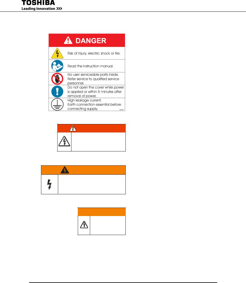
Safety Label Explanations
DANGER/ATTENTION
risk of electrical shock. do n ot touch u nin su lat ed batt ery terminals. batteries sh ould be serviced b y qua lified service repre se ntative only. miswiring of batt ery could result in ele ctrcal sh ock a nd/or fire.
risque de choc electrique . le circuit des ba tteries nest pa s e so led e secteur. le s cosses des ba tteries peu ven t prese nter une te nsion dange reu se part rapport a la terre . Ve rifier avan t de to uch er.
WARNING
This unit contains sealed lead acid batteries. lack of preventative maintenance could result
in batteries exploding and emitting gasses and/or flame. Annual preventative maintenance must be performed by an authorized, trained technician.
 WARNING
CRITICAL FUSE SIZING
incorrect fu se replacem ent size may result in fire or inadeq uate
equ ipm ent protection.
re pla ce only with same t ype and rating of fuse.
P/N 63094 – External warning sign.
•Unit contains potentially dangerous voltages.
•Read the instruction manual before operating.
•There are no user serviceable parts inside.
Refer service to qualified personnel.
•Do not open the cover while power is applied, or within five minutes after removal of power.
•Potentially hazardous leakage current may exist. Ensure the grounding is connected before connecting the utility power..
P/N 48518 – Battery terminals can deliver dangerous electrical shock. Service by qualified service representatives only.
P/N 49455 – UPS Batteries require annual preventative maintenance. Failure to perform regular maintenance could result in batteries exploding, or emitting gasses or flame.
P/N 49455 – Replace Fuse only with one of same type and range. Incorrect fuse size may result in equipment damage.
1600XP Series Installation and Operation Manual |
11 |
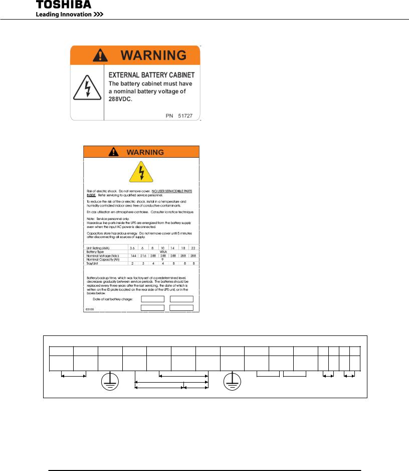
P/N 51727 – External Battery Cabinet Connection, nominal Battery Cabinet Voltage of 288VDC required.
P/N 63109 – There are no user-serviceable parts behind cover. Wait five minutes after disconnecting the UPS to allow the internal capacitors to discharge completely.
Date of last recorded battery change.
USE COPPER 90o CONDUCTORS ONLY. REFER TO INSTRUCTION MANUAL REGARDING TORQUE OF TERMINAL BLOCKS. FACTORY WIRED FOR 208V INPUT.
1 |
2 |
3 |
4 |
5 |
6 |
7 |
8 |
11 |
12 |
13 |
|
L1 |
L2 |
G |
X1 |
X2 |
N |
X3 |
G |
208V |
COM |
240V |
|
(L*) |
(N*) |
(0V*) |
|||||||||
|
|
|
|
|
|
|
|
208/240V |
208V |
|
|
240V |
INPUT VOLTAGE |
|
|
|
120V |
120V |
JUMPER SELECTION |
14 15 16 17
EPO1 |
EPO2 |
REMOTE |
REMOTE |
EPO REMOTE
INPUT |
OUTPUT |
( *) FOR SINGLE HOT WIRE |
P/N63093 - Power Terminal Label
12 |
1600XP Series Installation and Operation Manual |
UPS
Connections
Terminal Block
The following illustration is a detail view of the terminal block and wiring connections used for 208/240 volt units (see pages 65-66 for terminal block location).
1 |
2 |
3 |
4 |
5 |
6 |
7 |
8 |
11 |
|
12 |
13 |
14 |
15 |
16 |
17 |
L1 (L*) L2 |
(N*) |
G |
X1 |
X2 |
N (0V) |
X3 |
G |
208 |
COM |
240 |
EPO1 |
EPO2 REMOTE1 |
REMOTE2 |
||
|
|
|
|
|
208 V |
|
|
208V |
240V |
|
|
|
|
||
208/240 Vin |
|
|
240 V |
|
|
|
|
|
|
||||||
|
|
|
|
Jumper selection |
|
|
|
|
|||||||
|
|
|
|
|
|
|
|
|
|
|
|
||||
|
|
|
120 V |
120 V |
|
See notes 1&2 |
|
|
|
|
|||||
INPUT |
|
|
|
OUTPUT |
|
|
|
|
|
|
|
|
|
|
|
* – If only one input line is hot, connect hot line to terminal 1 (L), and connect the Neutral line to terminal 2 (N).
Note 1 – If AC input power is 208 Vac rated, short terminals 11 and 12 with a jumper wire. DO NOT jumper terminal 13 to 12 or 11. Factory Setting is 208Vac. Use the jumper wire provided by Toshiba. DO NOT add any additional jumpers.
Note 2 – If AC input power is 240 Vac rated, short terminals 12 and 13 with a jumper wire. DO NOT jumper terminal 11 to 12 or 13. Use the jumper wire provided by Toshiba. DO NOT add any additional jumpers.
1600XP Series Installation and Operation Manual |
13 |

Wire Size and Tightening Torque
Use the following table to select the recommended wire size and terminal lug tightening torque for I/O wire connections. Use 90 °C copper conductors for all Input, Output, and Ground wiring.
|
Terminal |
|
|
|
Cable Size - AWG |
|
Tightening |
||
Item |
|
|
|
|
|
|
|
Torque |
|
Number |
3.6 |
|
|
|
|
|
|
||
|
6 kVA |
8 kVA |
10 kVA |
14-18 kVA |
22 kVA |
lb.-in. (N•m) |
|||
|
|
kVA |
|||||||
|
|
|
|
|
|
|
|
|
|
AC Input Lines |
1 and 2 |
10 (8) |
8 (8) |
8 |
(1/0) |
6 (1/0) |
4 (1/0) |
1 (1/0) |
14.2 (1.56) |
AC Output Lines |
4, 5, and 7 |
12 (8) |
10 (8) |
8 |
(1/0) |
6 (1/0) |
4 (1/0) |
1 (1/0) |
14.2 (1.56) |
AC Output Neutral |
6 |
12 (8) |
10 (8) |
8 |
(1/0) |
6 (1/0) |
4 (1/0)) |
1 (1/0) |
14.2 (1.56) |
Ground |
3 and 8 |
12 (8) |
10 (8) |
8 |
(1/0) |
6 (1/0) |
4 (1/0)) |
1 (1/0) |
14.2 (1.56) |
EPO Switch |
14 and 15 |
16 |
16 |
|
16 |
16 |
16 |
16 |
9.0 (0.99) |
Remote Switch |
16 and 17 |
16 |
16 |
|
16 |
16 |
16 |
16 |
9.0 (0.99) |
Note: Wire size is presented as the recommended size followed by a bold number in () that is the maximum wire size the terminal block can accommodate. See page 64 for knock-out hole sizes on the back of each model.
14 |
1600XP Series Installation and Operation Manual |
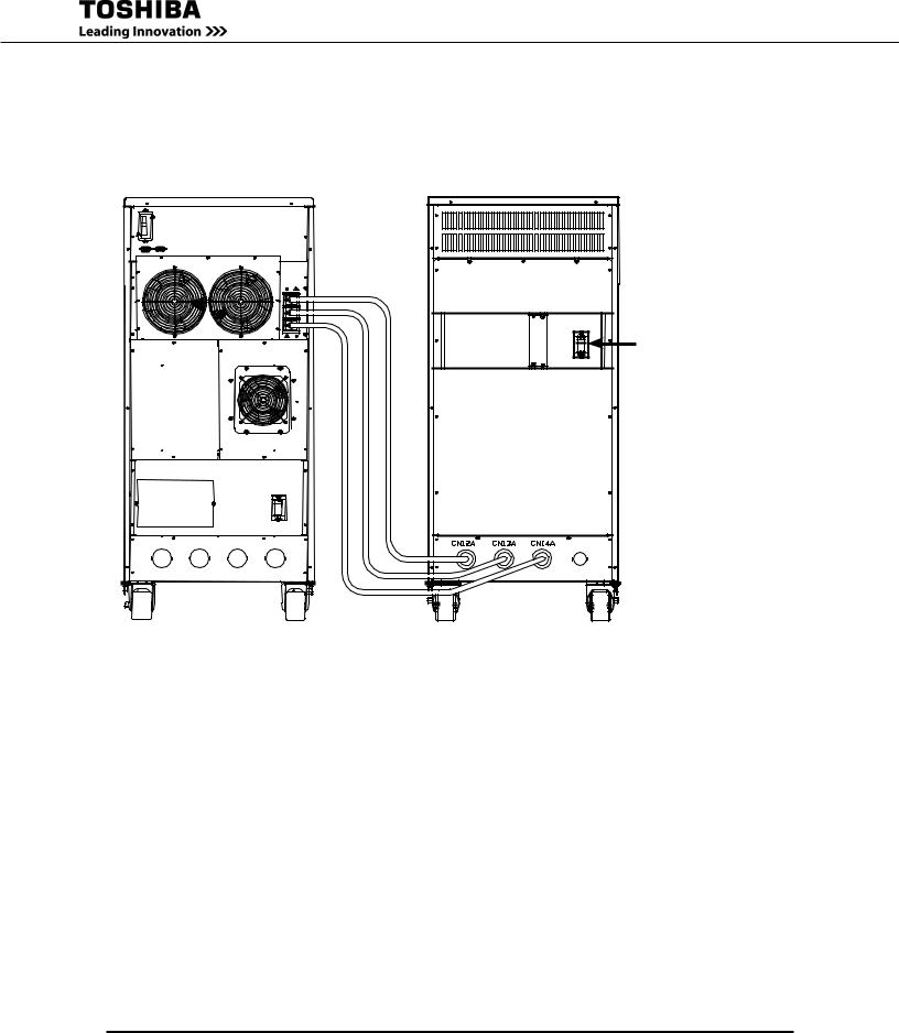
Optional Battery Cabinet Connections
Optional external battery cabinets can be used to extend the backup time of the UPS beyond that available with the internal batteries. The external battery cabinets connect to the UPS via Anderson-style connectors.
mCCb |
(battery Cabinet |
main Circuit |
breaker) |
UPS Model |
Battery Cabinet |
|
MCCB Capacity |
3.6, 6 kVA |
50 A |
8, 10, 14, 18, 22 kVA |
100 A |
See the applicable battery cabinet manual for additional details.
1600XP Series Installation and Operation Manual |
15 |
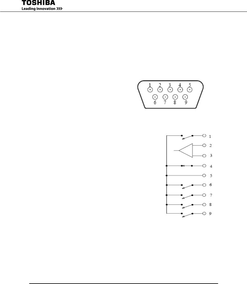
Communication Interfaces
Remote Contacts
The remote contacts interface is provided as a set of solid state switching devices. The switches are available through a DB9 male connector on the rear of the UPS. The following chart shows the pin assignment for each signal.
Maximum current carrying capacity |
DB9 Male Connector Outline |
|
Of the switch |
(Facing connector) |
|
|
|
|
Voltage |
Current |
|
48 Vdc peak |
70 mA peak |
|
30 Vac rms |
50 mA rms |
|
(42 Vac peak) |
(70 mA peak) |
|
Pin |
Signal Function |
Logic |
In the UPS |
1 |
Fault Signal |
Closed when fault detected |
|
|
|
|
|
2 |
UPS stop common |
Backup stop when the level |
|
3 |
UPS stop signal input |
changes from Low (-3 to -15 V) to |
|
High (+3 to +15 V) |
|
||
|
|
|
|
|
|
|
|
4 |
Normal input power supply |
Closed with normal supply power |
|
|
|
|
|
5 |
Signal common |
Common signal return |
|
|
|
|
|
6 |
Bypass operation |
Closed during bypass operation |
|
|
|
|
|
7 |
Battery voltage drop |
Closed at voltage drop |
|
|
|
|
|
8 |
UPS operation |
Closed during inverter operation |
|
|
|
|
|
9 |
Power failure signal |
Closed at power failure |
|
|
|
|
|
Note: |
Pin switches are shown in their inactive states. For example, if battery voltage is low, pin 7 will be connected to pin 5. |
||
16 |
1600XP Series Installation and Operation Manual |

UPS LAN Shutdown Signal Operation
When the UPS stop signal is sent to the UPS through pin 2 and 3 of the external contact interface, it is possible to automatically reset the following operating systems (OS), which can automatically implement the shutdown function and restart the operation: Windows NT, IBM OS/2 LAN server, LANtastic
Parameter 646 – UPS Shutdown by LAN Input Signal Enabled/Disabled
Parameter 647 – UPS Shutdown by LAN Signal Permitted Time Window (Adjustable)
With the UPS Shutdown by LAN Signal function enabled, when line power fails and the UPS goes to backup the LAN will shutdown even if the UPS returns to normal mode during the shutdown process.
LAN shutdown can take several minutes. The UPS Shutdown by LAN Signal function has a companion
UPS Shutdown by LAN Signal Permitted Time Window parameter that can be set to allow sufficient time to complete the LAN shutdown process (default: 10 minutes) even if line power is restored during LAN shutdown.
LAN shutdown is treated as a restart after battery shutdown. The restart of the LAN will be determined by the Restart After Battery Shutdown timer.
Connect only the UPS stop signal to the external contact interface for automatic processing so that the UPS output will not be turned off by mistake.
If the computer is started/restarted within 10 minutes after the recovery from a power failure, the power supply may be reset while the computer is restarting.
1600XP Series Installation and Operation Manual |
17 |
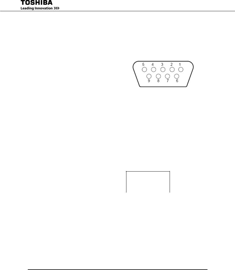
RS-232C
The RS232C port can be used by authorized service personnel. The port is provided using a DB9 female connector located on the rear of the UPS. For reference, the pinout of the connector is illustrated below.
|
RS-232C Connector Pin Assignment |
DB9 female Connector Outline |
||
|
|
|
|
(Facing connector) |
|
|
|
|
|
Pin |
I/O |
Symbol |
Description |
|
1 |
|
This pin is not used |
|
|
2 |
Input |
RXD |
Receive data |
|
3 |
Output |
TXD |
Transmit data |
|
4 |
Output |
DTR |
Data terminal ready |
|
5 |
- |
SG |
Signal ground |
|
6 |
Input |
DSR |
Data set ready |
|
7 |
Output |
RTS |
Request to send |
|
8 |
Input |
CTS |
Clear to send |
|
|
|
|
|
|
9 |
|
This pin is not used |
|
|
RemotEye III Network Card
The RemotEye III is an optional network card for the Toshiba UPS. This card slides into a slot located on the back side (page 65-66) of the UPS. The card provides a network, or LAN-based communication interface for the UPS. When installed, the UPS can be managed remotely using the common SNMP and HTTP web-based network protocols. The following diagram shows the flow of the Network Management
Station.
toshiba ups
|
|
|
|
|
|
|
|
network management |
|
remoteye III |
|
||
|
station or pc with |
|
|
|||
|
|
network card |
|
|||
|
web browser |
|
|
|||
|
|
|
|
|
||
|
|
|
|
|
|
|
|
|
|
|
|
|
|
network ethernet backbone
18 |
1600XP Series Installation and Operation Manual |

UPS Specifications
Standard Model: 3.6 – 10 kva
Unit (Capacity) |
3.6kVA (3.1 kW) 1 |
|
6 kVA (5.1 kW) 1 |
|
8 kVA (6.8 kW) 1 |
|
10 kVA (8.5 kW) 1 |
|
General |
|
|
|
|
|
|
|
|
Topology |
|
|
True On-Line |
|
||||
Certifications |
ANSI C62.41 (IEEE 587), UL 1778, CUL, CE, FCC Class A , NEC (NFPS-70), NEMA/ |
|||||||
PE1-1993, OSHA, ASME, ISO 9001, ISO 14001:2004 , RoHS Compliant |
||||||||
|
||||||||
Input Characteristics |
|
|
|
|
|
|
|
|
Input Voltage1 |
|
|
Single-phase, 208/240 Vac, +10% to -30%1 |
|
||||
Input Frequency |
|
|
45 – 65 Hz (auto-sensing) |
|
||||
Input Capacity |
3.6 kVA |
|
6 kVA |
|
8.0 kVA |
|
10 kVA |
|
Input /(Max Input) Current @208V |
17.9 (18.7) A |
|
29.8 (31.1) A |
|
38.9 (40.5) A |
|
48.6 (50.2) A |
|
Input/(Max. Input) Current @240V |
15.5 (16.2) A |
|
25.9 (27.0) A |
|
33.7 (35.1) A |
|
42.1 (43.5) A |
|
Input Power Factor |
|
|
0.98 Typical, 0.95 Minimum@ 100% Load |
|
||||
Current THD (linear load) |
|
|
< 5% total harmonic distortion |
|
||||
Internal AC Input Breaker Rating |
30 A/277 V |
|
50 A/277 V |
|
60 A/277 V |
|
63 A/277 V |
|
Battery Characteristics |
|
|
|
|
|
|
|
|
Battery Type |
|
Valve Regulated Lead Acid, Flame Retardant |
||||||
Backup time, fully charged @ 0.7 |
8 min.2 |
|
8 min.2 |
|
7 min.2 |
|
7 min.2 |
|
power factor, 77 °F |
|
|
|
|||||
|
|
|
|
|
|
|
||
Backup time, fully charged @ 0.85 |
7 min.2 |
|
7 min.2 |
|
7 min.2 |
|
5 min.2 |
|
power factor, 77 °F |
|
|
|
|||||
|
|
|
|
|
|
|
||
Recharge Time |
24 hr. (full), 12 hr. (90%) for internal batteries only3 |
|||||||
Battery Voltage (Nominal) |
144 Vdc |
|
216 Vdc |
|
288 Vdc |
|||
Output Characteristics |
|
|
|
|
|
|
|
|
Output Voltage |
|
|
Single-phase, 240/208/120 V |
|
||||
Output Voltage Regulation |
|
= ± 3% |
|
|
||||
Output Frequency |
±0.5 Hz/1.0 Hz/1.5 Hz (factory or authorized service center selectable only) |
|||||||
AUTO/MAN Frequency |
Factory or authorized service center selectable only |
|||||||
Voltage THD |
|
< 3% for linear load; < 6% for non-linear load |
||||||
Common-Mode Noise |
|
|
< 0.5 Vrms |
|
||||
Rated Load Power Factor1 |
|
|
0.85 (0.6 – 1.0) lagging |
|
||||
Efficiency (ac-dc-ac) |
>83% |
|
>85% |
|||||
Voltage Transient |
|
|
< ±8% (Load of 0 – 100 %) |
|
||||
Voltage Transient Recovery |
|
|
50 ms to within 2% of nominal |
|
||||
Rated Output Current (rms) |
15 A |
|
25 A |
|
33.3 A |
|
41.6 A |
|
Max Peak Output Current |
45 A |
|
75 A |
|
100 A |
|
125 A |
|
Inverter Overload Capacity |
|
|
125% for 30 sec./150% for 10 sec. |
|
||||
Bypass Overload Capacity |
|
|
125% for 10 min./1000% for 1 cycle |
|
||||
Crest Factor |
|
|
|
3.0 |
|
|
||
|
|
|
|
|
|
|
|
|
1.Input/output figures rated for 240 volts unless otherwise stated. Output ratings given for 0.85PF are only valid when the input voltage is greater than 204 volts; otherwise, ratings given for 0.70PF are applicable.
2.Battery backup time may vary depending on the operating conditions and ambient temperature at the installation site.
3.An initial charge time of 24 hrs. is necessary to obtain proper battery performance level before unit is placed in operation.
1600XP Series Installation and Operation Manual |
19 |
 Loading...