


Toshiba RAS-05J2KVG-TR, RAS-07J2KVG-TR, RAS-10J2KVG-TR, RAS-13J2KVG-TR, RAS-16J2KVG-TR INSTALLATION MANUAL
...INSTALLATION MANUAL
AIR CONDITIONER (SPLIT TYPE)
Indoor unit
RAS-05, 07, 10, 13, 16, 18J2KVG-TR RAS-05, 07, 10, 13, 16, 18J2KVG-EE RAS-05, 07, 10, 13, 16, 18TKVG-EE
Outdoor unit
RAS-05, 07, 10, 13, 16, 18J2AVG-TR RAS-05, 07, 10, 13, 16, 18J2AVG-EE RAS-05, 07, 10, 13, 16, 18TAVG-EE
1122950109_S04_182x257_52p_S_p70_181217_EN+TR+RU.indd 1
R32
ENGLISH
TÜRKÇE
PУCСКИЙ
1122950109
12/25/2018 10:46:49 AM 

EN |
CONTENTS |
|
PRECAUTIONS FOR SAFETY .............................................. |
1 |
|
ACCESSORY PARTS ............................................................ |
4 |
|
INSTALLATION DIAGRAM OF INDOOR AND |
|
|
OUTDOOR UNITS .................................................................. |
5 |
|
Optional Installation Parts ................................................. |
5 |
|
INDOOR UNIT ........................................................................ |
6 |
|
Installation Place ............................................................... |
6 |
|
Cutting a Hole and Mounting Installation Plate ................. |
6 |
|
Piping and Drain Hose Installation .................................... |
6 |
|
Indoor Unit Fixing .............................................................. |
7 |
|
Drainage ........................................................................... |
7 |
|
OUTDOOR UNIT .................................................................... |
8 |
|
Installation Place ............................................................... |
8 |
|
Precautions about Installation in Regions with Snowfall |
|
|
and Cold Temperatures ..................................................... |
8 |
|
Draining the Water ............................................................ |
9 |
|
Refrigerant Piping Connection .......................................... |
9 |
|
Evacuating....................................................................... |
10 |
|
ELECTRICAL WORKS ........................................................ |
11 |
|
Wiring Connection ........................................................... |
11 |
|
Power Supply and Connecting Cable Connection .......... |
12 |
|
Power Supply Input Wiring Diagram ............................... |
13 |
|
OTHERS |
............................................................................... |
14 |
Gas Leak Test ................................................................. |
14 |
|
Remote Control A-B Selection ........................................ |
14 |
|
Test Operation ................................................................. |
14 |
|
Auto Restart Setting ........................................................ |
14 |
|
APPENDIX ........................................................................... |
15 |
|
RU |
СОДЕРЖАНИЕ |
|
MEPЫ БEЗOПACHOCTИ ..................................................... |
1 |
|
ДОПОЛНИТЕЛЬНЫЕ ДЕТАЛИ ............................................ |
5 |
|
СХЕМА УСТАНОВКИ ВНУТРЕННЕГО И НАРУЖНОГО |
|
|
БЛОКОВ ................................................................................. |
6 |
|
Oпционaльныe Уcтaновочныe Чacти ............................. |
6 |
|
BHУTPEHHИЙ БЛOК ............................................................ |
7 |
|
Mecто Уcтaновки ............................................................. |
7 |
|
Пpоpeзaниe Отвepcтия и Монтaж Уcтaновочной |
|
|
Плacтины .......................................................................... |
7 |
|
Уcтaновкa Tpyбопpоводов и Дpeнaжной Tpyбки ........... |
8 |
|
Уcтaновкa Bнyтpeннeго Блокa ........................................ |
9 |
|
Дpeнaж.............................................................................. |
9 |
|
HAPУЖHЫЙ БЛOК ............................................................... |
9 |
|
Mecто Уcтaновки .............................................................. |
9 |
|
Меры безопасности при установке в регионах, |
|
|
в которых возможно выпадение снега и низкие |
|
|
температуры .................................................................... |
9 |
|
Сливводы....................................................................... |
10 |
|
Подcоeдинeниe Tpyбопpоводa для Xлaдaгeнтa .......... |
10 |
|
Удaлeниe Воздyxa .......................................................... |
11 |
|
ЭЛEКТPОМОНТAЖНЫE РAБОТЫ ................................... |
12 |
|
Элeктpичecкиe Cоeдинeния ......................................... |
12 |
|
Подключение источника питания и соединительного |
|
|
кабеля ............................................................................ |
13 |
|
Схема электрических соединений ............................... |
14 |
|
ДPУГИE |
................................................................................ |
15 |
Пpовepкa Отcyтcтвия Утeчки Гaзa ............................... |
15 |
|
ВыборА-ВнапультеДУ................................................. |
15 |
|
ПpобнaяЭкcплyaтaция.................................................. |
15 |
|
УcтaновкaAвтомaтичecкого Повтоpного Пycкa ........... |
15 |
|
ПРИЛОЖЕНИЕ .................................................................... |
16 |
|
TR İÇİNDEKİLER |
|
GÜVENLİK ÖNLEMLERİ ....................................................... |
1 |
AKSESUAR PARÇALARI ...................................................... |
4 |
İÇ VE DIŞ ÜNITENIN MONTAJ ŞEMASI ............................... |
5 |
İsteğe Bağlı Montaj Parçaları ............................................ |
5 |
İÇ ÜNİTE ................................................................................ |
6 |
Montaj Yeri ........................................................................ |
6 |
Bir Delik Açılması ve Montaj Plakasının Yerleştirilmesi ..... |
6 |
Boruların Bağlanması ve Boşaltma Hortumunun Monte |
|
edilmesi ............................................................................. |
6 |
İç Ünitenin Takılması ......................................................... |
7 |
Su Boşaltma ...................................................................... |
7 |
DIŞ ÜNİTE .............................................................................. |
8 |
Montaj Yeri ........................................................................ |
8 |
Karlı ve Soğuk Bölgelerde Montaj İle İlgili Önlemler ......... |
8 |
Su Tahliyesi ....................................................................... |
9 |
Soğutma Maddesi Boru Bağlantısı ................................... |
9 |
Boşaltma.......................................................................... |
10 |
ELEKTRİK İŞLERİ ............................................................... |
11 |
Kablo Bağlantısı .............................................................. |
11 |
Güç Kaynağı ve Bağlantı Kablosu Bağlantısı .................. |
12 |
Güç Kaynağı girişi Kablo Şeması ................................... |
13 |
DİĞERLERİ .......................................................................... |
14 |
Gaz Kaçağı Testi ............................................................. |
14 |
Uzaktan Kumanda ile A-B Seçimi ................................... |
14 |
Test İşlemi ....................................................................... |
14 |
Otomatik Yeniden Başlama Ayarı .................................... |
14 |
EK ......................................................................................... |
15 |
1122950109_S04_182x257_52p_S_p70_181217_EN+TR+RU.indd 2 |
12/25/2018 10:46:49 AM |

PRECAUTIONS FOR SAFETY
Read the precautions in this manual carefully before operating the unit.
 This appliance is filled with R32.
EN
•Before installation, please read these precautions for safety carefully.
•Be sure to follow the precautions provided here to avoid safety risks. The symbols and their meanings are shown below.
WARNING : It indicates that incorrect use of this unit may cause severe injury or death.
CAUTION : It indicates that incorrect use of this unit may cause personal injury
(*1), or property damage (*2).
*1: Personal injury means a slight accident, burn, or electrical shock which does not require admission or repeated hospital treatment.
*2: Property damage means greater damage which affects assets or resources.
For general public use
Power supply cord and connecting cable of appliance use shall be at least polychloroprene sheathed flexible cord (design H07RN-F) or cord designation
60245 IEC66. (Shall be installed in accordance with national wiring regulations.)
CAUTION |
To disconnect the appliance from the main power supply |
|
This appliance must be connected to the main power supply by means of a circuit breaker or a switch with a contact separation of at least 3 mm in all poles.
DANGER
•FOR USE BY QUALIFIED PERSONS ONLY.
•TURN OFF MAIN POWER SUPPLY BEFORE ATTEMPTING ANY ELECTRICAL WORK. MAKE SURE ALL POWER SWITCHES ARE OFF.
FAILURE TO DO SO MAY CAUSE ELECTRIC SHOCK.
•CONNECT THE CONNECTING CABLE CORRECTLY. IF THE CONNECTING CABLE IS CONNECTED WRONGLY, ELECTRIC PARTS MAY BE DAMAGED.
•CHECK THE EARTH WIRE THAT IT IS NOT BROKEN OR DISCONNECTED BEFORE INSTALLATION.
•DO NOT INSTALL NEAR CONCENTRATIONS OF COMBUSTIBLE GAS OR
GAS VAPORS.
FAILURE TO FOLLOW THIS INSTRUCTION CAN RESULT IN FIRE OR EXPLOSION.
1
1122950109_S04_182x257_52p_S_p70_181217_EN+TR+RU.indd 3 |
12/25/2018 10:46:49 AM |

•TO PREVENT OVERHEATING THE INDOOR UNITAND CAUSING A FIRE
HAZARD, PLACE THE UNIT WELLAWAY (MORE THAN 2 M) FROM HEAT
SOURCES SUCH AS RADIATORS, HEATERS, FURNACE, STOVES, ETC.
•WHEN MOVING THE AIR CONDITIONER FOR INSTALLING IT IN ANOTHER
PLACE AGAIN, BE VERY CAREFUL NOT TO GET THE SPECIFIED
REFRIGERANT (R32) WITH ANY OTHER GASEOUS BODY INTO THE
REFRIGERATION CYCLE. IF AIR OR ANY OTHER GAS IS MIXED IN THE
REFRIGERANT, THE GAS PRESSURE IN THE REFRIGERATION CYCLE BECOMES ABNORMALLY HIGH AND IT RESULTINGLY CAUSES BURST OF
THE PIPE AND INJURIES ON PERSONS.
•IN THE EVENT THAT THE REFRIGERANT GAS LEAKS OUT OF THE PIPE
DURING THE INSTALLATION WORK, IMMEDIATELY LET FRESH AIR INTO
THE ROOM. IF THE REFRIGERANT GAS IS HEATED BY FIRE OR
SOMETHING ELSE, IT CAUSES GENERATION OF POISONOUS GAS.
WARNING
•Never modify this unit by removing any of the safety guards or bypassing any of the safety interlock switches.
•Do not install in a place which cannot bear the weight of the unit. Personal injury and property damage can result if the unit falls.
•Before doing the electrical work, attach an approved plug to the power supply cord.
Also, make sure the equipment is properly earthed.
•Appliance shall be installed in accordance with national wiring regulations.
If you detect any damage, do not install the unit. Contact your dealer immediately.
•Do not use any refrigerant different from the one specified for complement or replacement.
Otherwise, abnormally high pressure may be generated in the refrigeration cycle, which may result in a failure or explosion of the product or an injury to your body.
•Do not use means to accelerate the defrosting process or to clean, other than those recommended by the manufacturer.
•The appliance shall be stored in a room without continuously operating ignition sources (for example: open flames, an operating gas appliance or an operating electric heater).
•Be aware that refrigerants may not contain an odour.
•Do not pierce or burn as the appliance is pressurized. Do not expose the appliance to heat, flame, sparks, or other sources or ignition. Else, it may explode and cause injury or death.
•For R32 model, use pipes, flare nut and tools which is specified for R32 refrigerant. Using of existing (R22) piping, flare nut and tools may cause abnormally high pressure in the refrigerant cycle (piping), and possibly result in explosion and injury.
•Thickness of copper pipes used R32 must be more than 0.8 mm. Never use copper pipes thinner than 0.8 mm.
2
1122950109_S04_182x257_52p_S_p70_181217_EN+TR+RU.indd 4 |
12/25/2018 10:46:49 AM |
•After completion of installation or service, confirm there is no leakage of refrigerant gas. It may generate toxic gas when the refrigerant contacts with fire.
•Comply with national gas regulations.
CAUTION |
|
• Exposure of unit to water or other moisture before installation could result in |
EN |
electric shock. |
|
Do not store it in a wet basement or expose to rain or water. |
|
•After unpacking the unit, examine it carefully for possible damage.
•Do not install the unit at place where leakage of flammable gas may occur. In case gas leaks and accumulates at surrounding of the unit, it may cause of fire.
•Do not install in a place that can increase the vibration of the unit. Do not install in a place that can amplify the noise level of the unit or where noise and discharged air might disturb neighbors.
•To avoid personal injury, be careful when handling parts with sharp edges.
•Please read this installation manual carefully before installing the unit. It contains further important instructions for proper installation.
•The manufacturer shall not assume any liability for the damage caused by not observing the description of this manual.
REQUIREMENT OF REPORT TO THE LOCAL POWER SUPPLIER Please make absolutely sure that the installation of this appliance is reported to the local power supplier before installation. If you experience any problems or if the installation is not accepted by the supplier, the service agency will take adequate countermeasures.
■Important information regarding the refrigerant used
This product contains fluorinated greenhouse gases.
Do not vent gases into the atmosphere.
Refrigerant type: R32
GWP(1) value: 675 * (ex. R32 ref. AR4)
(1)GWP = global warming potential
The refrigerant quantity is indicated on the unit name plate.
* This value is based on F gas regulation 517/2014
3
1122950109_S04_182x257_52p_S_p70_181217_EN+TR+RU.indd 5 |
12/25/2018 10:46:49 AM |

ACCESSORY PARTS
Indoor Unit
No. |
Part name |
No. |
Part name |
1 |
|
2 |
|
|
Installation plate × 1 |
|
Wireless remote control × 1 |
3 |
|
4 |
|
|
Battery × 2 |
|
Remote control holder × 1 |
5 |
Mounting screw × 6 |
6 |
Flat head wood screw × 2 |
|
|
||
7 |
|
8 |
|
|
Owner’s Manual × 1 |
|
Installation Manual × 1 |
|
|
Outdoor Unit |
|
No. |
Part name |
No. |
Part name |
9 |
|
10 |
|
|
Drain nipple × 1 |
|
Cap water proof × 2* |
* Not require to use for RAS-05, 07, 10, 13J2AVG and RAS-05, 07, 10, 13TAVG
Air filters
Clean every 2 weeks.
1. Open the air inlet grille.
2. Remove the air flters.
3. Vacuum or wash and then dry them.
4. Reinstall the air flters and close the air inlet grille.
4
1122950109_S04_182x257_52p_S_p70_181217_EN+TR+RU.indd 6 |
12/25/2018 10:46:49 AM |
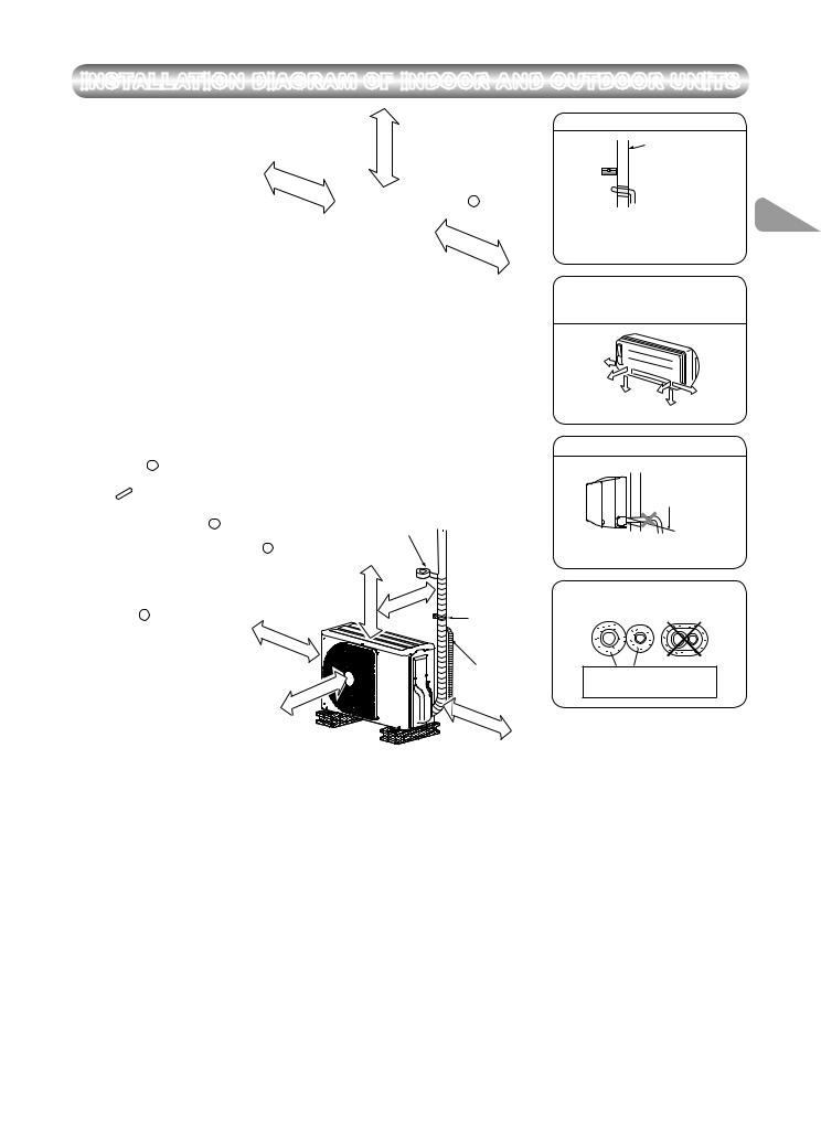
INSTALLATION DIAGRAM OF INDOOR AND OUTDOOR UNITS
|
|
|
|
|
|
|
|
|
|
|
<![if ! IE]> <![endif]>65 mm or more |
|
Hook |
|
|
|
|
|
|
|
|
|
|
|
300 |
mm |
|
|
|
|
|
|
|
|
|
|
|
|
|
|
|
|
|
|
|
|
|
|
|
|
|
|
|
|
|
|
|
|
|
or |
|
|
|
|
|
|
|
|
|
|
|
|
|
|
|
|
|
more |
|
|
|
|
1 |
Installation |
|
|
|
|
|
|
|
|
|
|
|
|
|
|
|
|
plate |
|
|
|
|
|
|
|
|
|
|
|
|
|
300 |
mm |
|
|
|
|
|
|
|
|
|
|
|
|
|
|
|
|
|
||
|
|
|
|
|
|
|
|
|
|
|
|
|
|
|
or |
|
|
|
|
|
|
|
|
|
|
|
Hook |
|
|
|
|
more |
|
|
|
|
|
|
|
|
|
|
|
|
|
|
|
|
||
|
|
|
|
|
|
|
|
Air |
|
|
|
|
|
|
|
|
|
|
|
|
|
|
|
|
filter |
|
|
|
|
|
|
|
|
|
|
|
|
|
|
|
|
|
|
|
|
|
|
|
|
Shield pipe |
|
|
(Attach |
to |
the |
|
|
|
|
Refrigerant piping |
|
|
|
|
|
||
|
|
|
|
front |
|
|
|
must be protected from |
|
|
|
|||||
|
|
|
|
|
panel.) |
|
|
|
|
|
||||||
|
|
|
|
|
|
|
|
|
|
|
||||||
|
|
|
|
|
|
|
|
|
physical damage. |
|
|
|
|
|
||
|
|
|
|
|
|
|
|
|
|
|
|
|
|
|
||
|
|
|
|
|
|
|
|
|
|
Install a plastic cover or |
|
|
|
|||
|
3 |
Batteries |
|
|
|
|
|
|
|
equivalent. |
|
|
|
|
|
|
|
|
|
|
|
|
|
|
|
|
|
|
|
|
|
||
|
|
|
|
|
|
|
|
|
|
Vinyl tape |
|
|
|
|
||
|
|
|
|
6 |
|
|
|
|
|
Apply after carrying |
|
|
|
|||
|
|
|
|
|
|
|
|
|
out a drainage test. |
|
|
|
||||
|
|
|
Flat head |
|
|
|
|
|
|
|
||||||
|
|
|
|
|
|
|
|
|
|
|
|
|
|
|||
|
|
|
wood screw |
4 |
|
|
|
|
|
|
|
|
|
|||
|
|
|
|
|
|
|
|
|
|
|
|
|
|
|
|
|
|
|
|
|
|
|
|
Remote control |
|
|
|
|
|
|
|
||
|
|
|
|
|
|
|
holder |
|
|
|
|
|
|
|
|
|
|
|
|
|
|
|
|
|
|
|
<![if ! IE]> <![endif]>more |
|
|
more |
|
|
|
|
|
|
|
|
|
|
|
|
|
<![if ! IE]> <![endif]>or |
|
|
|
|
|
|
|
|
|
|
|
|
|
|
|
|
|
|
or |
|
|
|
|
|
|
|
|
|
|
|
|
|
|
<![if ! IE]> <![endif]>C mm |
|
mm |
|
|
|
|
|
2 |
Wireless remote control |
|
|
|
E |
|
|
|
|
||||||
|
|
|
|
|
|
|
|
Saddle |
||||||||
|
|
|
|
|
|
|
F |
mm |
|
|
|
|
|
|
|
|
|
|
|
|
|
|
|
|
|
|
|
|
|
|
|
|
|
|
|
|
|
|
|
|
|
or |
|
|
|
|
|
|
|
|
|
|
|
|
|
|
|
|
|
more |
|
|
|
|
|
|
|
|
RAS-05, 07, 10, 13J2AVG-TR |
RAS-16, 18J2AVG-TR |
|
|
|
|
|
|
Extension drain hose |
|||||||
|
|
|
|
|
|
|
(Not available, provided |
|||||||||
|
RAS-05, 07, 10, 13J2AVG-EE |
RAS-16, 18J2AVG-EE |
|
|
|
|
|
|
||||||||
|
|
|
|
|
|
|
by installer) |
|||||||||
|
RAS-05, 07, 10, 13TAVG-EE |
RAS-16, 18TAVG-EE |
|
|
ormore |
|
|
|
||||||||
|
|
|
|
|
|
|
|
|
mm |
|
|
|
|
|
|
|
C |
600 |
|
|
|
600 |
|
|
D |
|
|
|
|
|
|
|
|
|
|
|
|
|
|
|
|
|
C |
|
|
|||||
D |
400 |
|
|
|
600 |
|
|
|
|
|
|
mm or |
||||
|
|
|
|
|
|
|
|
|
|
|
||||||
E |
45 |
|
|
|
100 |
|
|
|
|
|
|
|
|
|
more |
|
|
|
|
|
|
|
|
|
|
|
|
|
|
||||
F |
100 |
|
|
|
100 |
|
|
|
|
|
|
|
|
|
|
|
For the rear left, bottom left and left piping
Wall |
|
Cut out a piece of SPACER from indoor |
EN |
unit packaging box, roll it and insert |
|
between the indoor unit and wall to tilt |
|
the indoor unit for better operation. |
|
The auxiliary piping can be connected to the left, rear left, rear right, right, bottom right or bottom left.
Right |
|
|
|
Rear |
|
|
|
right |
|
Left |
|
Bottom |
Rear |
||
|
|||
right |
left |
Bottom left |
|
|
|
Do not allow the drain hose to get slack.
Cut the piping hole sloped slightly.
Make sure to run the drain hose sloped downward.
Insulate the refrigerant pipes separately with insulation, not together.
6 mm thick heat resisting polyethylene foam
Optional Installation Parts
Part |
|
Parts name |
Q’ty |
|
code |
|
|||
|
|
|
||
|
|
|
||
|
Refrigerant piping |
|
||
|
Liquid side |
: Ø6.35 mm |
|
|
|
|
(RAS-05, 07, 10, 13J2KVG-TR) |
|
|
|
|
(RAS-05, 07, 10, 13J2KVG-EE) |
One |
|
A |
|
(RAS-05, 07, 10, 13TKVG-EE) |
||
|
each |
|||
|
Gas side |
: Ø12.70 mm |
||
|
|
|||
|
|
(RAS-16, 18J2KVG-TR) |
|
|
|
|
(RAS-16, 18J2KVG-EE) |
|
|
|
|
(RAS-16, 18TKVG-EE) |
|
|
|
|
|
||
B |
Pipe insulating material |
1 |
||
(polyethylene foam, 6 mm thick) |
||||
|
|
|||
|
|
|
|
|
C |
Putty, PVC tapes |
One |
||
each |
||||
|
|
|
||
|
|
|
|
|
Fixing bolt arrangement of outdoor unit
•Secure the outdoor unit with fixing bolts and nuts if the unit is likely to be exposed to a strong wind.
•Use Ø8 mm or Ø10 mm anchor bolts and nuts.
•If it is necessary to drain the defrost water, attach drain nipple 9 and cap water proof 10 to the bottom plate of the outdoor unit before installing it.
|
|
|
|
|
|
|
108 mm |
|
125 mm |
|
|
|
|
|
|
|
28 mm |
mm |
Air inlet |
|
|
|
|
500 mm |
|
Ø25 |
|||
|
|
|
|
|
|
||||
|
|
|
|
|
|
<![if ! IE]> <![endif]>102mm |
|||
|
|
|
|
<![if ! IE]> <![endif]>mm |
<![if ! IE]> <![endif]>mm86 |
|
|||
|
|
|
|
|
<![if ! IE]> <![endif]>mm |
|
|||
|
|
|
|
97 mm |
Air inlet |
|
|
|
|
| <![if ! IE]> <![endif]>mm |
<![if ! IE]> <![endif]>mm |
<![if ! IE]> <![endif]>mm |
Ø25 |
mm |
<![if ! IE]> <![endif]>340 |
<![if ! IE]> <![endif]>320 |
|
|
|
|
|
|
|
|
|
|
|
|
|
| <![if ! IE]> <![endif]>300 |
<![if ! IE]> <![endif]>280 |
<![if ! IE]> <![endif]>53 |
|
|
|
|
|
|
|
|
|
|
|
|
|
|
Air outlet |
|
90 mm |
|
|
|
|
|
|
|
|
|
|
|
|
|
Air outlet |
|
|
600 mm |
|
|
|
|
|
|
Drain outlet |
|
|
|
Drain outlet |
||
|
|
|
|
|
|
|
|
||
|
|
RAS-05, 07, 10, 13J2AVG-TR |
|
RAS-16, 18J2AVG-TR |
|||||
|
|
RAS-05, 07, 10, 13J2AVG-EE |
|
RAS-16, 18J2AVG-EE |
|||||
|
|
RAS-05, 07, 10, 13TAVG-EE |
|
RAS-16, 18TAVG-EE |
|||||
5
1122950109_S04_182x257_52p_S_p70_181217_EN+TR+RU.indd 7 |
12/25/2018 10:46:50 AM |

INDOOR UNIT
Installation Place
•A place which provides the spaces around the indoor unit as shown in the diagram
•A place where there are no obstacles near the air inlet and outlet
•A place which allows easy installation of the piping to the outdoor unit
•A place which allows the front panel to be opened
•The indoor unit shall be installed at least 2.5 m height. Also, it must be avoided to put anything on the top of the indoor unit.
CAUTION
•Direct sunlight to the indoor unit’s wireless receiver should be avoided.
•The microprocessor in the indoor unit should not be too close to RF noise sources.
(For details, see the owner’s manual.)
Remote control
•A place where there are no obstacles such as a curtain that may block the signal from the indoor unit
•Do not install the remote control in a place exposed to direct sunlight or close to a heating source such as a stove.
•Keep the remote control at least 1 m apart from the nearest TV set or stereo equipment. (This is necessary to prevent image disturbances or noise interference.)
•The location of the remote control should be determined as shown below.
|
(Side view) |
|
(Top view) |
|
| <![if ! IE]> <![endif]>unit |
|
|
Indoor unit |
|
|
|
|
|
|
| <![if ! IE]> <![endif]>Indoor |
|
|
° |
|
|
|
45 |
45° |
|
|
|
|
||
|
° |
|
Reception |
|
|
75 |
|
|
|
|
|
Remote |
|
|
|
Reception |
range |
Remote |
|
|
control |
|||
|
range |
control |
||
|
|
|
Cutting a Hole and Mounting
Installation Plate
 Cutting a hole
When installing the refrigerant pipes from the rear
Pipe hole 
 Ø65 mm
The center of the pipe hole |
120 mm |
|
is above the arrow. |
||
|
1. After determining the pipe hole position on the mounting plate ( ), drill the pipe hole (Ø65 mm) at a slight downward slant to the outdoor side.
NOTE
•When drilling a wall that contains a metal lath, wire lath or metal plate, be sure to use a pipe hole brim ring sold separately.
 Mounting the installation plate
|
|
Hook |
|
65 |
103 |
|
|
|
|
||
300 |
|
|
|
|
300 |
|
|
|
|
|
|
144 |
|
|
|
50 |
|
50 |
|
|
|
|
|
|
|
|
|
|
|
|
|
|
|
|
1 |
Pipe hole |
Hook |
|
|
Hook |
Installation |
Thread |
|
Pipe hole |
plate |
||
Indoor unit |
|
||||
|
Weight |
5 |
Mounting screw |
|
|
|
|
|
|
When the installation plate is directly mounted on the wall
1.Securely fit the installation plate onto the wall by screwing it in the upper and lower parts to hook up the indoor unit.
2.To mount the installation plate on a concrete wall with anchor bolts, use the anchor bolt holes as illustrated in the below figure.
3.Install the installation plate horizontally in the wall.
CAUTION
When installing the installation plate with a mounting screw, do not use the anchor bolt holes. Otherwise, the unit may fall down and result in personal injury and property damage.
Installation plate
(Keep horizontal direction.)
|
Anchor bolt |
|
Projection |
5 mm dia. hole |
15 mm or less |
|
5 Mounting screw Ø4 mm x 25 ℓ

 Clip anchor (local parts)
CAUTION
Failure to firmly install the unit may result in personal injury and property damage if the unit falls.
•In case of block, brick, concrete or similar type walls, make 5 mm dia. holes in the wall.
•Insert clip anchors for appropriate mounting screws 5 .
NOTE
•Secure four corners and lower parts of the installation plate with 4 to 6 mounting screws to install it.
Piping and Drain Hose Installation
 Piping and drain hose forming
*Since dewing results in a machine trouble, make sure to insulate both connecting pipes. (Use polyethylene foam as insulating material.)
Rear right |
|
|
|
|
|
|
|
|
|
|
|
|
|
|
|
|
|
|
|
|
|
|
|
Rear left |
|
|
|
|
<![if ! IE]> <![endif]>Changing drainhose |
|
<![if ! IE]> <![endif]>preparationPiping |
|
|
|
|
|
|
||
|
|
|
|
||||
Bottom left |
|
<![if ! IE]> <![endif]>cutting-Die |
<![if ! IE]> <![endif]>slitbodyback |
||||
|
|
|
|
|
|
|
|
|
|
|
|
|
|
|
|
|
|
|
|
|
|
|
|
Left |
|
|
|
|
|
|
|
|
|
|
|
|
|
|
|
|
|
|
|
|
|
|
|
Bottom right |
|
|
|
|
|
|
|
|
|
|
|
|
|
|
|
|
|
|
|
|
|
|
|
Right |
|
|
|
|
|
|
|
|
|
|
|
|
|
|
|
1.Die-cutting back body slit
Cut out the slit on the left or right side of the back body for the left or right connection and the slit on the bottom left or right side of the back body for the bottom left or right connection with a pair of nippers.
2.Changing drain hose
For leftward connection, bottom-leftward connection and rearleftward connection’s piping, it is necessary to change the drain hose and drain cap.
6
1122950109_S04_182x257_52p_S_p70_181217_EN+TR+RU.indd 8 |
12/25/2018 10:46:52 AM |

How to remove the drain hose
• The drain hose can be removed by removing the screw securing the drain hose and then pulling out the drain hose.
• When removing the drain hose, be careful of any 


 sharp edges of steel plate. The edges can injuries.


• To install the drain hose, insert the drain hose firmly until the connection part contacts with heat insulator, and then secure it with original screw.
Drain hose
How to remove the drain cap
Clip the drain cap by needle-nose pliers and pull out.
How to fiix the drain cap
1) Insert hexagon wrench (4 mm) in a center head.
2) Firmly insert the drain cap.
Do not apply lubricating oil (refrigerant machine oil) when inserting the drain cap. Application causes deterioration and drain leakage of the plug.
No gap
 Insert a hexagon wrench (4 mm).
NOTE
If the pipe is bent incorrectly, the indoor unit may unstably be set on the wall. After passing the connecting pipe through the pipe hole, connect the connecting pipes to the auxiliary pipes and wrap the facing tape around them.
CAUTION
•Bind the auxiliary pipes (two) and connecting cable with facing tape tightly. In case of leftward piping and rear-leftward piping, bind the auxiliary pipes (two) only with facing tape.
EN
 Indoor unit
Auxiliary pipes 


 Connecting cable
Installation plate 
•Carefully arrange pipes so that any pipe does not stick out of the rear plate of the indoor unit.
•Carefully connect the auxiliary pipes and connecting pipes to one another and cut off the insulating tape wound on the connecting pipe to avoid double-taping at the joint; moreover, seal the joint with the vinyl tape, etc.
•Since dewing results in a machine trouble, make sure to insulate both connecting pipes. (Use polyethylene foam as insulating material.)
•When bending a pipe, carefully do it, not to crush it.
CAUTION
Firmly insert the drain hose and drain cap; otherwise, water may leak.
 In case of right or left piping
• After scribing slits of the back body with a knife or a making-off pin, cut them with a pair of nippers or an equivalent tool.
Slit 


 In case of bottom right or bottom left piping
• After scribing slits of the back body with a knife or a making-off pin, cut them with a pair of nippers or an equivalent tool.
Slit
 Left-hand connection with piping
•Bend the connecting pipe so that it is laid within 43 mm above the wall surface. If the connecting pipe is laid exceeding 43 mm above the wall surface, the indoor unit may unstably be set on the wall.
When bending the connecting pipe, make sure to use a spring bender so as not to crush the pipe.
Bend the connecting pipe within a radius of 30 mm.
To connect the pipe after installation of the unit (figure)
|
|
(To the forefront of flare) |
|
260 mm |
Gas side |
|
210 mm |
Liquid side |
|
|
|
|
|
Outward form of indoor unit |
| <![if ! IE]> <![endif]>mm |
R 30 mm (Use polisin (polyethylene) |
|
| <![if ! IE]> <![endif]>43 |
core or the like for bending pipe.) |
|
Indoor Unit Fixing
1.Pass the pipe through the hole in the wall and hook the indoor unit on the installation plate at the upper hook.
2.Swing the indoor unit to right and left to confirm that it is firmly hooked up on the installation plate.
3.While pressing the indoor unit onto the wall, hook it at the lower part on the installation plate. Pull the indoor unit toward you to confirm that it is firmly hooked up on the installation plate.
Hook here.
 Installation plate
Hook  Press
Press
(unhook)
•For detaching the indoor unit from the installation plate, pull the indoor
unit toward you while pushing its bottom up at the specified parts.
Push
Push
Drainage
1. Run the drain hose sloped downwards.
NOTE
• The hole should be made at a slight downward slant on the outdoor side.
Do not rise the drain hose.
50 mm or more
Do not from the drain hose into a wavy shape.
Do not put the |
Do not put the |
drain hose end |
drain hose end |
into water. |
in the drainage ditch. |
° 80
Use the handle of screwdriver, etc.
7
1122950109_S04_182x257_52p_S_p70_181217_EN+TR+RU.indd 9 |
12/25/2018 10:46:53 AM |

2.Put water in the drain pan and make sure that the water is drained out of doors.
3.When connecting extension drain hose, insulate the connecting part of extension drain hose with shield pipe.
|
Shield pipe |
|
Drain hose |
Inside the room |
Extension drain hose |
|
CAUTION |
|
|
Arrange the drain pipe for proper drainage from the unit. |
|
|
Improper drainage can result in dew-dropping. |
|
|
This air conditioner has the structure designed |
|
|
to drain water collected from dew, which forms |
Wall |
|
on the back of the indoor unit, to the drain pan. |
||
Drain |
||
Therefore, do not store the power cord and other |
||
parts at a height above the drain guide. |
guide |
|
|
||
Space for pipes |
|
OUTDOOR UNIT
Installation Place
•A place which provides the spaces around the outdoor unit as shown in the diagram
•A place which can bear the weight of the outdoor unit and does not allow an increase in noise level and vibration
•A place where the operation noise and discharged air do not disturb your neighbors
•A place which is not exposed to a strong wind
•A place free of a leakage of combustible gases
•A place which does not block a passage
•When the outdoor unit is to be installed in an elevated position, be sure to secure its feet.
•The allowable length of the connecting pipe.
Model |
RAS-05, 07, 10, 13J2AVG-TR |
RAS-16, 18J2AVG-TR |
RAS-05, 07, 10, 13J2AVG-EE |
RAS-16, 18J2AVG-EE |
|
|
RAS-05, 07, 10, 13TAVG-EE |
RAS-16, 18TAVG-EE |
|
|
|
Chargeless |
Up to 15 m |
Up to 15 m |
|
|
|
Maximum length |
15 m |
20 m |
|
|
|
Additional refrigerent charging |
– |
16 – 20 m (20 g / 1 m) |
|
|
|
• The allowable height of outdoor unit installation site.
Model |
RAS-05, 07, 10, 13J2AVG-TR |
RAS-16, 18J2AVG-TR |
RAS-05, 07, 10, 13J2AVG-EE |
RAS-16, 18J2AVG-EE |
|
|
RAS-05, 07, 10, 13TAVG-EE |
RAS-16, 18TAVG-EE |
|
|
|
Maximum height |
12 m |
12 m |
|
|
|
• A place where the drain water does not raise any problems
CAUTION
When the outdoor unit is installed in a place where the drain water might cause any problems, Seal the water leakage point tightly using a silicone adhesive or caulking compound.
Precautions about Installation in Regions with Snowfall and Cold Temperatures
•Do not use the supplied drain nipple for draining water. Drain the water from all the drain holes directly.
•To protect the outdoor unit from snow accumulation, install a holding frame, and attach a snow protection hood and plate.
* Do not use a double-stacked design.
|
Snow protection plate |
Front |
|
|
Snow protection hood |
|
At least 50 cm |
Anchor |
Snow accumulation line |
bolts |
Holding frame |
|
Install at least 50 cm above the snow accumulation line.
Precautions for adding refrigerant
•Use a scale having a precision with at least 10 g per index line when adding the refrigerant.
Do not use a bathroom scale or similar instrument.
•Use liquid refrigerant when reflling the refrigerant. Since the refrigerant is in liquid form, it can fll quickly.
Therefore, perform the flling operation carefully and insert the refrigerant gradually.
CAUTION
1.Install the outdoor unit without anything blocking the air discharging.
2.When the outdoor unit is installed in a place always exposed to strong wind like a coast or on a high storey of a building, secure the normal fan operation using a duct or a windshield.
3.In particularly windy areas, install the unit such as to avoid admission of wind.
4.Installation in the following places may result in trouble. Do not install the unit in such places.
•A place full of machine oil
•A saline-place such as the coast
• |
A place full of sulfide gas |
|
• |
A place where high-frequency |
Strong |
|
waves are likely to be generated |
wind |
|
as from audio equipment, |
|
|
welders, and medical equipment |
|
8
1122950109_S04_182x257_52p_S_p70_181217_EN+TR+RU.indd 10 |
12/25/2018 10:46:55 AM |
Draining the Water
•Holes are provided on the base plate of the outdoor unit to ensure that the defrost water produced during heating operations is drained off efficiently. If a centralized drain isrequired when installing the unit on a balcony or
wall, follow the steps below to drain off the water.
1.Proceed with water-proofng by installing the water-proof rubber caps in the 2 elongated holes on the base plate of the outdoor unit. [How to install the water-proof rubber caps]
1)Place four fngers into each cap, and insert the caps into the water drain holes by pushing them into place from the underside of the base plate.
2)Press down on the outer circumferences of the caps to ensure that they have been inserted tightly.
(Water leaks may result if the caps have not been inserted properly, if their outer circumferences lift up or the caps catch on or wedge against something.)
|
|
IMPERIAL (wing nut type) |
|
|
|
A |
|
|
|
Outer dia.of copper pipe |
R32 |
Die |
Pipe |
Ø6.35 |
1.5 to 2.0 |
|
|
Ø9.52 |
1.5 to 2.0 |
|
|
Ø12.70 |
2.0 to 2.5 |
|
|
Pipes thickness |
0.8 mm or more |
CAUTION |
|
EN |
|
•Do not scratch the inner surface of the flared part when removing burrs.
•Flare processing under the condition of scratches on the inner surface of flare processing part will cause refrigerant gas leak.
Water-proof rubber caps (supplied with the outdoor unit)

 Base plate
 Drain nipple
2.Install the drain nipple and a commercially available drain hose (with 16 mm inside diameter), and drain off the water.
(For the position where the drain nipple is installed, refer to the installation diagram of the indoor and outdoor units.)
•Check that the outdoor unit is horizontal, and route the drain hose at a downward sloped angle while ensuring that it is connected tautly.
Base plate |
Drain nipple |
Commercially available drain hose
Do not use ordinary garden hose, but one can fatten and preven water from draining.
Refrigerant Piping Connection
 Tightening connection
Align the centers of the connecting pipes and tighten the flare nut as far as possible with your fingers. Then tighten the nut with a spanner and torque wrench as shown in the figure.
Half union |
Flare nut |
Externally |
Internally |
threaded side |
threaded side |
Use a wrench to secure. |
Use a torque wrench to tighten. |
CAUTION
Do not apply excess torque. Otherwise, the nut may crack depending on the conditions.
|
(Unit : N·m) |
|
|
Outer dia.of copper pipe |
Tightening torque |
|
|
Ø6.35 mm |
16 to 18 (1.6 to 1.8 kgf·m) |
|
|
Ø9.52 mm |
30 to 42 (3.0 to 4.2 kgf·m) |
|
|
Ø12.70 mm |
50 to 62 (5.0 to 6.2 kgf·m) |
|
|
• Tightening torque of flare pipe connections
The operating pressure of R32 is higher than that of R22 (approx. 1.6 times). It is therefore
necessary to firmly tighten the flare pipe connecting sections (which connect the indoor and outdoor units) up to the specified tightening torque. Incorrect connections may cause not only a
gas leakage, but also damage to the refrigeration cycle.
Flare at
indoor unit side


 Flare at
outdoor unit side
 Flaring
1. Cut the pipe with a pipe cutter.
90° |
Obliquity |
Roughness |
Warp |
|
|
|
2.Insert a flare nut into the pipe and flare the pipe.
•Projection margin in flaring : A (Unit : mm)
RIDGID (clutch type)
Outer dia.of copper pipe |
R32 tool used |
Conventional tool |
||
used |
||||
|
|
|
||
|
|
|
|
|
Ø6.35 |
0 to 0.5 |
|
1.0 to 1.5 |
|
|
|
|
|
|
Ø9.52 |
0 to 0.5 |
|
1.0 to 1.5 |
|
|
|
|
|
|
Ø12.70 |
0 to 0.5 |
|
1.0 to 1.5 |
|
|
|
|
|
|
Pipes thickness |
|
0.8 mm or more |
||
|
|
|
|
|
9
1122950109_S04_182x257_52p_S_p70_181217_EN+TR+RU.indd 11 |
12/25/2018 10:46:55 AM |
 Loading...