


 Loading...
TEC Label Printer
B-419-GS10-QQ
 Owner's Manual

0This equipment has been tested and found to comply with the limits for a Class A digital device, pursuant to Part 15 of the FCC Rules, These limits are designed to provide reasonable protection against harmful interference when the equipment is operated in a commercial environment. This equipment generates, uses, and can radiate radio frequency energy and, if not installed and used in accordance with the instruction manual, may cause harmful interference to radio communications. Operations of this equipment in a residential area is likely to cause harmful interference in which case the user will be required to correct the interference at his own expense.
(for USA only)
Changes or modifications not expressly approved by manufacturer for compliance could void the user’s authority to operate the equipment.
“This Class A digital apparatus meets all requirements of the Canadian Interference-Causing Equipment Regulations.”
“Cet appareil numérique de la classe A respecte toutes les exigences du Règlement sur le matériel brouilleur du Canada.”
(for CANADA only)
Copyright © 2001
by TOSHIBA TEC CORPORATION All Rights Reserved
570 Ohito, Ohito-cho, Tagata-gun, Shizuoka-ken, JAPAN
Safety Summary |
EO1-33030 |
6DIHW\ 6XPPDU\
Personal safety in handling or maintaining the equipment is extremely important. Warnings and Cautions necessary for safe handling are included in this manual. All warnings and cautions contained in this manual should be read and understood before handling or maintaining the equipment.
Do not attempt to effect repairs or modifications to this equipment. If a fault occurs that cannot be rectified using the procedures described in this manual, turn off the power, unplug the machine, then contact your authorized TOSHIBA TEC representative for assistance.
0HDQLQJV RI (DFK 6\PERO
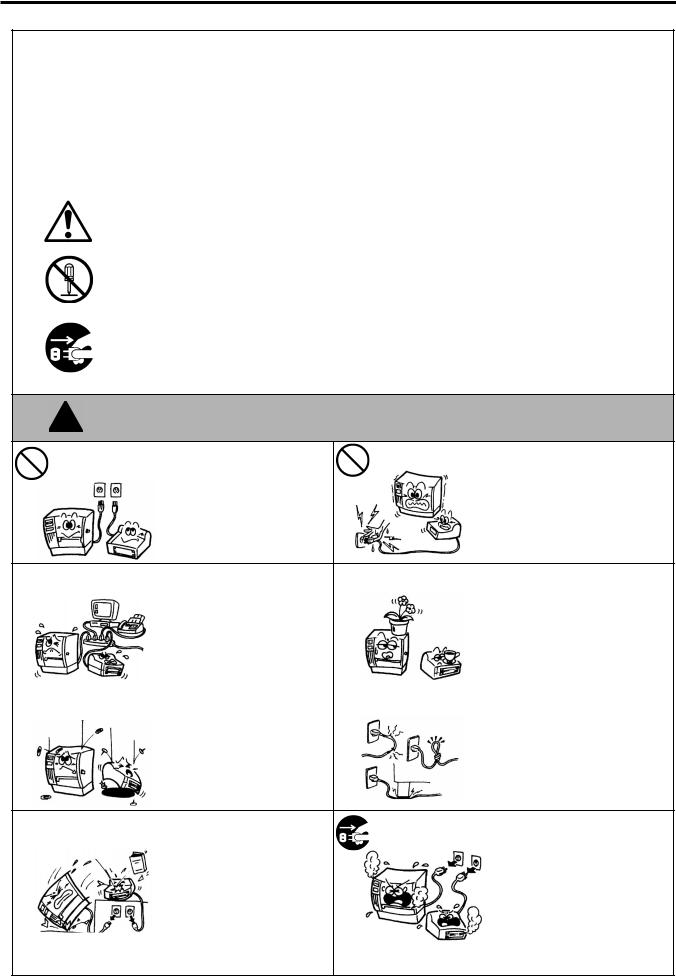
This symbol indicates warning items (including cautions). Specific warning contents are drawn inside the  symbol. (The symbol on the left indicates a general caution.)
This symbol indicates prohibited actions (prohibited items). Specific prohibited contents are drawn inside or near the  symbol. (The symbol on the left indicates “no disassembling”.)
This symbol indicates actions which must be performed.
Specific instructions are drawn inside or near the ● symbol.
(The symbol on the left indicates “disconnect the power cord plug from the outlet”.)
This indicates that there is the risk of death or serious injury if the :$51,1* machines are improperly handled contrary to this indication.
$Q\ RWKHU WKDQ WKH |
Do not use voltages other than |
|
Do not plug in or unplug the power |
|
|
3URKLELWHG |
|
||
VSHFLILHG $& YROWDJH the voltage (AC) specified on the |
cord plug with wet hands as this |
|||
|
||||
LV SURKLELWHG |
rating plate, as this may cause |
|
may cause electric shock. |
|
|
fire or electric shock. |
|
|
|
|
|
3URKLELWHG |
If the machines share the same |
|
|
Do not place metal objects or |
|
|
|
outlet with any other electrical |
|
3URKLELWHG |
water-filled containers such as |
||
|
|
|
appliances which consume large |
|
|
flower vases, flower pots or mugs, |
|
|
|
|
|
|
|||
|
|
|
amounts of power, the voltage |
|
|
etc. on top of the machines. If |
|
|
|
|
will fluctuate widely each time |
|
|
metal objects or spilled liquid enter |
|
|
|
|
these appliances operate. Be sure |
|
|
the machines, this may cause fire |
|
|
|
|
to provide an exclusive outlet for |
|
|
or electric shock. |
|
|
|
|
the machine as this may cause |
|
|
|
|
|
|
|
fire or electric shock. |
|
|
|
|
|
|
3URKLELWHG |
Do not insert or drop metal, |
|
|
3URKLELWHG |
Do not scratch, damage or modify |
|
|
|
|
||||
|
|
flammable or other foreign |
|
|
the power cords. Also, do not |
||
|
|
|
objects into the machines through |
|
|
|
place heavy objects on, pull on, or |
|
|
|
|
|
|
||
|
|
|
the ventilation slits, as this may |
|
|
excessively bend the cords, as this |
|
|
|
|
cause fire or electric shock. |
|
|
may cause fire or electrical shock. |
|
|
'LVFRQQHFW |
If the machines are dropped or |
'LVFRQQHFW |
Continued use of the machines in |
|
their cabinets damaged, first turn |
an abnormal condition such as |
||
|
WKH SOXJ |
WKH SOXJ |
||
|
off the power switches and |
when the machines are producing |
||
|
|
|
||
|
|
disconnect the power cord plugs |
|
smoke or strange smells may cause |
|
|
from the outlet, and then contact |
|
fire or electric shock. In these |
|
|
your authorized TOSHIBA TEC |
|
cases, immediately turn off the |
|
|
representative for assistance. |
|
power switches and disconnect the |
|
|
Continued use of the machine in |
|
power cord plugs from the outlet. |
|
|
that condition may cause fire or |
|
Then, contact your authorized |
|
|
electric shock. |
|
TOSHIBA TEC representative for |
|
|
|
|
assistance. |
( i )
Safety Summary |
EO1-33030 |
|
|
|
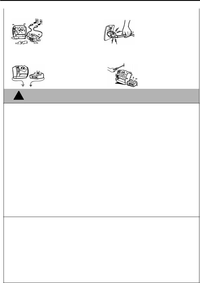
If foreign objects (metal |
|
|
|
|
When unplugging the power cords, |
|
|
|
|
|
|
|
||
|
|
'LVFRQQHFW |
fragments, water, liquids) enter |
|
|
|
'LVFRQQHFW |
be sure to hold and pull on the plug |
|
|
WKH SOXJ |
the machines, first turn off the |
|
|
|
WKH SOXJ |
portion. Pulling on the cord portion |
|
|
|
power switches and disconnect |
|
|
|
|
may cut or expose the internal wires |
|
|
|
the power cord plugs from the |
|
|
|
|
and cause fire or electric shock. |
|
|
|
outlet, and then contact your |
|
|
|
|
|
|
|
|
authorized TOSHIBA TEC |
|
|
|
|
|
|
|
|
representative for assistance. |
|
|
|
|
|
|
|
|
Continued use of the machine in |
|
|
|
|
|
|
|
|
that condition may cause fire or |
|
|
|
|
|
|
|
|
electric shock. |
|
|
|
|
|
|
|
&RQQHFW D |
Ensure that the equipment is |
|
|
|
1R |
Do not remove covers, repair or |
|
|
|
|
|
||||
|
|
properly grounded. Extension |
|
|
|
modify the machine by yourself. |
||
|
|
JURXQGLQJ ZLUH |
cables should also be grounded. |
|
|
|
GLVDVVHPEOLQJ |
You may be injured by high |
|
|
|
|
|
|
|||
|
|
|
Fire or electric shock could |
|
|
|
|
voltage, very hot parts or sharp |
|
|
|
occur on improperly grounded |
|
|
|
|
edges inside the machine. |
|
|
|
equipment. |
|
|
|
|
|
|
|
|
|
|
|
|
|
|
This indicates that there is the risk of personal Injury or damage to &$87,21 objects if the machines are improperly handled contrary to this indication.
Precautions
The following precautions will help to ensure that this machine will continue to function correctly.
● Try to avoid locations that have the following adverse conditions: |
|
|
|||
* |
Temperatures out of the specification |
* |
Direct sunlight |
* |
High humidity |
* |
Shared power source |
* |
Excessive vibration |
* |
Dust/Gas |
●The cover should be cleaned by wiping with a dry cloth or a cloth slightly dampened with a mild detergent solution. NEVER USE THINNER OR ANY OTHER VOLATILE SOLVENT on the plastic covers.
●USE ONLY TOSHIBA TEC SPECIFIED paper and ribbons.
●DO NOT STORE the paper or ribbons where they might be exposed to direct sunlight, high temperatures, high humidity, dust, or gas.
●Ensure the printer is operated on a level surface.
●Any data stored in the memory of the printer could be lost during a printer fault.
●Try to avoid using this equipment on the same power supply as high voltage equipment or equipment likely to cause mains interference.
●Unplug the machine whenever you are working inside it or cleaning it.
●Keep your work environment static free.
●Do not place heavy objects on top of the machines, as these items may become unbalanced and fall causing injury.
●Do not block the ventilation slits of the machines, as this will cause heat to build up inside the machines and may cause fire.
●Do not lean against the machine. It may fall on you and could cause injury.
●Care must be taken not to injure yourself with the printer paper cutter.
●Unplug the machine when it is not used for a long period of time.
Request Regarding Maintenance
●Utilize our maintenance services.
After purchasing the machine, contact your authorized TOSHIBA TEC representative for assistance once a year to have the inside of the machine cleaned. Otherwise, dust will build up inside the machines and may cause a fire or a malfunction. Cleaning is particularly effective before humid rainy seasons.
●Our preventive maintenance service performs the periodic checks and other work required to maintain the quality and performance of the machines, preventing accidents beforehand.
For details, please consult your authorized TOSHIBA TEC representative for assistance.
●Using insecticides and other chemicals
Do not expose the machines to insecticides or other volatile solvents. This will cause the cabinet or other parts to deteriorate or cause the paint to peel.
( ii )
EO1-33030
|
|
|
|
TABLE OF CONTENTS |
|
|
|
|
|
|
Page |
1. |
PRODUCT OVERVIEW .......................................................................................................... |
1-1 |
|||
|
1.1 |
Introduction .................................................................................................................... |
1-1 |
||
|
1.2 |
Features ........................................................................................................................ |
1-1 |
||
|
1.3 |
Unpacking...................................................................................................................... |
1-1 |
||
|
1.4 |
Accessories .................................................................................................................. |
1-2 |
||
|
1.5 |
Appearance ................................................................................................................... |
1-2 |
||
|
|
1.5.1 |
Dimensions..................................................................................................................... |
1-2 |
|
|
|
1.5.2 |
Front View....................................................................................................................... |
1-3 |
|
|
|
1.5.3 Rear View ....................................................................................................................... |
1-3 |
||
|
|
1.5.4 |
Interior............................................................................................................................. |
1-3 |
|
|
|
1.5.5 |
Operation Panel.............................................................................................................. |
1-4 |
|
2. |
PRINTER SETUP ................................................................................................................... |
2-1 |
|||
|
2.1 |
Precautions.................................................................................................................... |
2-1 |
||
|
2.2 |
Procedure before Operation........................................................................................... |
2-2 |
||
|
2.3 |
Connecting the Cables to Your Printer ........................................................................... |
2-2 |
||
|
2.4 |
Connecting the Power Cord ........................................................................................... |
2-3 |
||
|
2.5 |
Turning the Printer ON/OFF........................................................................................... |
2-4 |
||
|
|
2.5.1 |
Turning ON the Printer ................................................................................................... |
2-4 |
|
|
|
2.5.2 |
Turning OFF the Printer ................................................................................................. |
2-4 |
|
|
2.6 |
Opening/Closing the Media Cover.................................................................................. |
2-5 |
||
|
2.7 |
Loading the Media ......................................................................................................... |
2-6 |
||
|
|
2.7.1 |
Loading the Fanfold Paper............................................................................................. |
2-7 |
|
|
|
2.7.2 Loading the Cut Form..................................................................................................... |
2-8 |
||
|
2.8 |
Removing/Installing the Paper Guide Unit...................................................................... |
2-9 |
||
|
2.9 |
Test Print ..................................................................................................................... |
2-10 |
||
|
2.10 |
Program Download ...................................................................................................... |
2-13 |
||
|
|
2.10.1 |
Outline of Features........................................................................................... |
2-13 |
|
|
|
2.10.2 |
Install Program Installation ............................................................................... |
2-13 |
|
|
|
2.10.3 |
Firmware Files Copy ........................................................................................ |
2-17 |
|
|
|
2.10.4 |
Sensor Adjustments ......................................................................................... |
2-23 |
|
|
|
2.10.5 |
Printer Information Registration........................................................................ |
2-26 |
|
|
|
2.10.6 |
Test Print.......................................................................................................... |
2-28 |
|
|
|
2.10.7 |
Version Display ................................................................................................ |
2-29 |
|
3. |
MAINTENANCE ..................................................................................................................... |
3-1 |
|||
|
3.1 |
Cleaning ........................................................................................................................ |
3-1 |
||
|
|
3.1.1 |
Print Head/Platen ........................................................................................................... |
3-1 |
|
|
|
3.1.2 |
Paper Path/Sensors ....................................................................................................... |
3-2 |
|
|
|
3.1.3 |
Covers ............................................................................................................................ |
3-2 |
|
|
3.2 |
Care/Handling of the Media ........................................................................................... |
3-2 |
||

EO1-33030
4. TROUBLESHOOTING............................................................................................................ |
4-1 |
|
4.1 |
LED State ...................................................................................................................... |
4-1 |
4.2 |
Error Process................................................................................................................. |
4-2 |
4.3 |
Possible Problems ......................................................................................................... |
4-3 |
4.4 |
Removing Jammed Media ............................................................................................. |
4-3 |
APPENDIX 1 SPECIFICATIONS................................................................................................. |
A1-1 |
|
A1.1 |
Printer .......................................................................................................................... |
A1-1 |
A1.2 |
Media........................................................................................................................... |
A1-2 |
|
A1.2.1 Media Type....................................................................................................... |
A1-2 |
APPENDIX 2 INTERFACE .......................................................................................................... |
A2-1 |
|
APPENDIX 3 PRINT SAMPLES.................................................................................................. |
A3-1 |
|
GLOSSARIES |
|
|
INDEX |
|
|
WARNING!
This is a Class A product. In a domestic environment this product may cause radio interference in which case the user may be required to take adequate measures.
CAUTION!
1.This manual may not be copied in whole or in part without prior written permission of TOSHIBA TEC.
2.The contents of this manual may be changed without notification.
3.Please refer to your local authorized service representative with regard to any queries you may have in this manual.

1. PRODUCT OVERVIEW |
EO1-33030 |
1.1 Introduction
1. PRODUCT OVERVIEW
1.1 Introduction
Thank you for choosing the TEC B-419 series label printer. This Owner’s Manual contains information about general set-up through how to confirm the printer’s operation using a test print. This manual should be read carefully to help gain maximum performance and life from your printer. For most queries please refer to this manual and keep it safe for future reference. Please contact your TOSHIBA TEC representative for further information concerning this manual.
1.2 Features
1.3 Unpacking
NOTES:
1.Check for damage or scratches on the printer. However, please note that TOSHIBA TEC shall have no liability for any damage of any kind sustained during transportation of the product.
2.Keep the cartons and packaging for future transportation of the printer.
The B-419 printer has the following features:
∙The paper auto feed function is provided for the first time for a 4 inch wide, small and light desk top printer.
∙To meet various applications, four types of issue modes, such as, the TEC Printer Command Language Light Edition (TPCL-LE) mode, high speed graphic mode, label issue mode, and receipt issue mode, are supported as standard.
For details, please inquire from your nearest TOSHIBA TEC representative.
∙This printer can print cut forms as standard, which allows ticket issuing.
Unpack the printer as per the Unpacking Instructions supplied with the printer.
1- 1
1. PRODUCT OVERVIEW |
EO1-33030 |
1.4 Accessories
1.4 Accessories
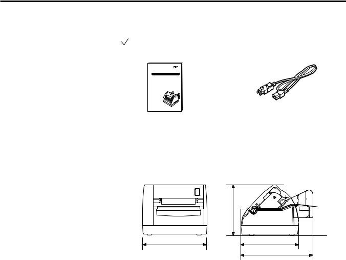
When unpacking the printer, please make sure all the following accessories have been supplied with the printer.
UOwner’s Manual (1 copy)
(Doc./No. EO1-33030)
TEC Label Printer |
B-419-GS10-QQ |
Owner's Manual |
TOSHIBA TEC CORPORATION |
UPower Cord (1 pc.) (P/No.FBCB0030202)
1.5 Appearance
1.5.1 Dimensions
The names of the parts or units introduced in this section are used in the following chapters.
|
5.1(130) |
6.6(167) |
5.9(150) |
|
7.4(187) |
Dimensions in inch+(mm)
1- 2
1. PRODUCT OVERVIEW |
EO1-33030 |
1.5 Appearance
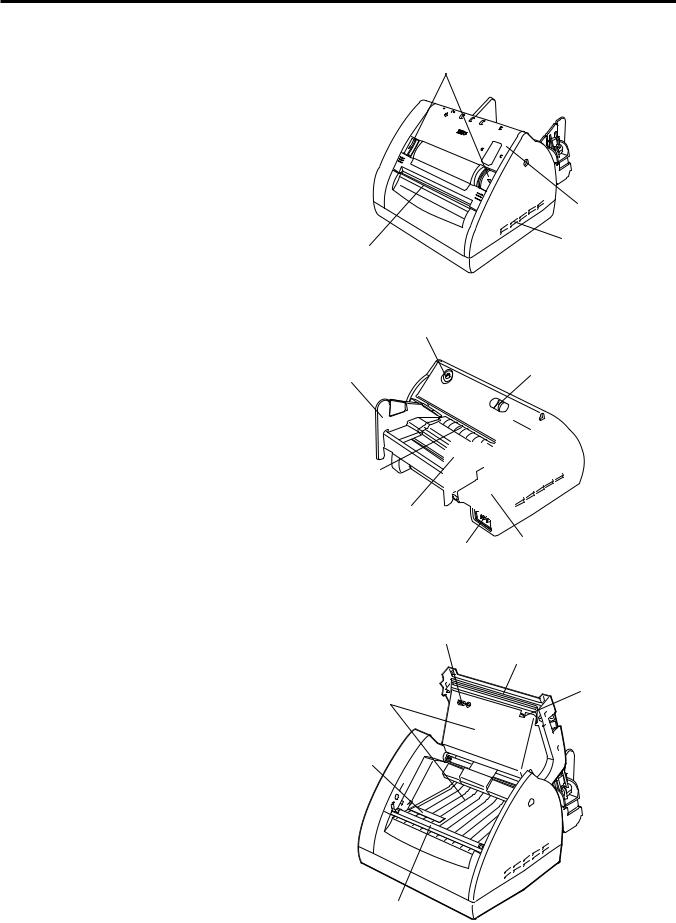
1.5.2 Front View
1.5.3 Rear View
Media Cover
Release Catch
Media Cover
Ventilator
Media Outlet
FEED Button
Paper Guide (R) |
Stand-by Switch |
Media Inlet
Paper Guide (L)
|
|
Serial Interface |
Inlet |
|
|
|
|
Connector (RS-232C) |
|
||
|
|
|
1.5.4 Interior
Feed Gap Sensor
Print Head
Thermistor
Paper Path Surface
Black Mark/
Feed Gap Sensor
Platen
1- 3
1. PRODUCT OVERVIEW |
EO1-33030 |
|
1.5 Appearance |
|
|
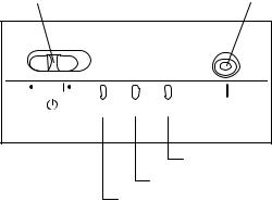
1.5.5 Operation Panel |
The figure below illustrates the Operation Panel and key functions. |
|
|
Stand-by Switch |
FEED Button |
ON LINE DATA ERROR |
FEED |
ERROR LED
DATA LED
ON LINE LED
There are three LED lights on the Operation Panel.
|
|
|
LED |
Illuminates when… |
Flashes when… |
|
|
|
|
ON LINE |
The printer is turned on. |
----- |
|
|
|
|
|
The printer is in operation. |
Flashes fast when the printer |
|
|
|
|
DATA |
(Goes off when in Idle.) |
is communicating with the |
|
|
|
|
|
|
PC. |
|
|
|
|
|
|
|
Flashes slowly when the |
|
|
|
|
|
|
print data remains. |
|
|
|
|
The print head has a |
Paper feed jam, cover open, |
|
|
|
|
ERROR |
broken element. |
communication error, etc. |
|
|
|
|
|
|
occurs. For details, refer to |
|
|
|
|
|
|
|
|
|
|
|
|
|
|
Section 4.1 LED State. |
|
There are two switches on the Operation Panel. |
|||||
CAUTION! |
|
|
|
|
A slide power switch. The power is turned ON |
|
Even if the Stand-by |
|
|
STAND-BY Switch |
when the switch is positioned to the (l) side. |
||
|
|
The power is turned OFF when the switch is |
||||
switch is turned off, the |
|
|
|
|
||
|
|
|
|
positioned to the other side. |
||
primary power remains |
|
|
|
|
||
|
|
FEED Button |
Each time this button is pressed, the printer |
|||
ON, as this switch turns |
|
|
||||
|
|
feeds one piece of media. |
||||
|
|
|
|
|||
on/off the secondary |
|
|
|
|
|
|
power supply only. |
|
|
|
|
|
|
When the printer is not |
|
|
|
|
|
|
used for a long time, |
|
|
|
|
|
|
disconnect the power cord |
|
|
|
|
|
|
from the AC outlet. |
|
|
|
|
|
|
|
|
|
|
|
|
|
2. PRINTER SETUP |
EO1-33030 |
2.1 Precautions
2. PRINTER SETUP
2.1 Precautions
This section outlines the procedures to setup your B-419 printer prior to its operation. The section includes precautions, connecting cables, assembling accessories, loading media, and performing a test print.
To ensure the best operating environment, and to assure the safety of the operator and the equipment, please observe the following precautions.
∙Operate the printer on a stable, level, operating surface in a location free from excessive humidity, high temperature, dust, vibration or direct sunlight.
∙Keep your work environment static free. Static discharge can cause damage to delicate internal components.
∙Make sure that the printer is connected to a clean source of AC Power and that no other high voltage devices that may cause line noise interference are connected to the same mains.
∙Ensure that the printer is connected to the AC mains with a threeprong power cable that has the proper ground (earth) connection.
∙Turn off the printer power and remove the power cord from the printer whenever working on the inside of the printer such as loading the media, or when cleaning the printer.
∙For best results, and longer printer life, use only TOSHIBA TEC recommended media.
∙Store the media in accordance with the specifications.
∙This printer mechanism contains high voltage components; therefore you should never remove any of the covers of the machine as you may receive an electrical shock. Additionally, the printer contains many delicate components that may be damaged if accessed by unauthorized personnel.
∙Clean the outside of the printer with a clean dry cloth or a clean cloth slightly dampened with a mild detergent solution.
∙Use caution when cleaning the thermal print head as it may become very hot while printing. Wait until it has had time to cool before cleaning.
∙Do not turn off the printer power or remove the power plug while the printer is printing or while the ON LINE lamp is blinking.
∙Ensure that there is an AC outlet that can be used only for the printer close to the printer installation location.
2- 1
2. PRINTER SETUP |
EO1-33030 |
2.2 Procedure before Operation
2.2Procedure before This section describes the outline of the printer setup.
Operation
1.Unpack the accessories and printer from the box.
NOTES:
1.To communicate with the host computer, a 9-pin RS232C cable is required.
2.The printer can also be controlled with its own programming commands. Please contact your TOSHIBA TEC reseller for the Interface/Communication Manual.
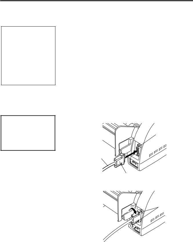
2.3Connecting the Cables to Your Printer
CAUTION!
The RS-232C must be connected while the power is turned OFF. Failure to do this may cause electric shock or short-circuit.
2.Refer to Safety Precautions in this manual and set up the printer in a suitable location.
3.The host computer must have a serial port. (Refer to Section 2.3.)
4.Be sure to insert the power cord plug into an AC outlet. (Refer to Section 2.4.)
5.Load the media in the printer. (Refer to Section 2.7.)
6.Turn the Power ON. (Refer to Section 2.5.)
7.Perform a test print. (Refer to Section 2.9.)
8.Install the Printer Drivers.
When connecting the RS-232C cable to your printer, follow the procedure described below.
1.Make sure that the power cord is not connected to the AC outlet.
2.Connect the printer side connector of the RS-232C cable to the serial port on the rear of the printer.
Serial Port
RS-232C Cable
Connector
3. Secure the connector with the screws.
Screw
4.Connect the PC side connector of the RS-232C cable to the Serial port of your PC.
2- 2
2. PRINTER SETUP |
EO1-33030 |
|
2.4 Connecting the Power Cord |
|
|
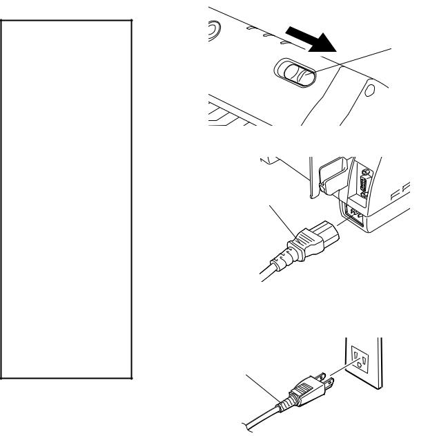
2.4 Connecting the |
1. Make sure that the Stand-by switch is in the OFF position. |
|
Power Cord |
|
|
CAUTION! |
|
|
1. Make sure that the |
Stand-by Switch |
|
printer Stand-by switch |
||
|
||
is turned to the off |
|
|
position before |
|
|
connecting the power |
|
|
cord to prevent possible |
|
|
electric shock or |
|
|
damage to the printer. |
|
2.Use only the power cord 2. Connect the Power Cord to the printer as shown in the figure below. supplied with the printer.
Use of any other cord may cause electric
shock or fire. |
|
3. Connect the power cord |
Power Cord |
to a three-prong outlet |
|
only, with the third prong |
|
being a good ground |
|
(earth) connection. |
|
4. Even if the Stand-by |
|
switch is turned off, the |
|
primary power remains |
3. Plug the other end of the Power Cord into the ground outlet as |
ON, as this switch turns |
|
on/off the secondary |
shown in the figure below. |
power supply only. |
|
When the printer is not |
|
used for a long time, |
|
disconnect the power |
|
cord from the AC outlet. |
Power Cord |
2- 3
2. PRINTER SETUP |
EO1-33030 |
2.5 Turning the Printer ON/OFF
2.5Turning the Printer ON/OFF
When the printer is connected to your host computer it is good practice to turn the printer ON before turning on your host computer and turn OFF your host computer before turning off the printer.
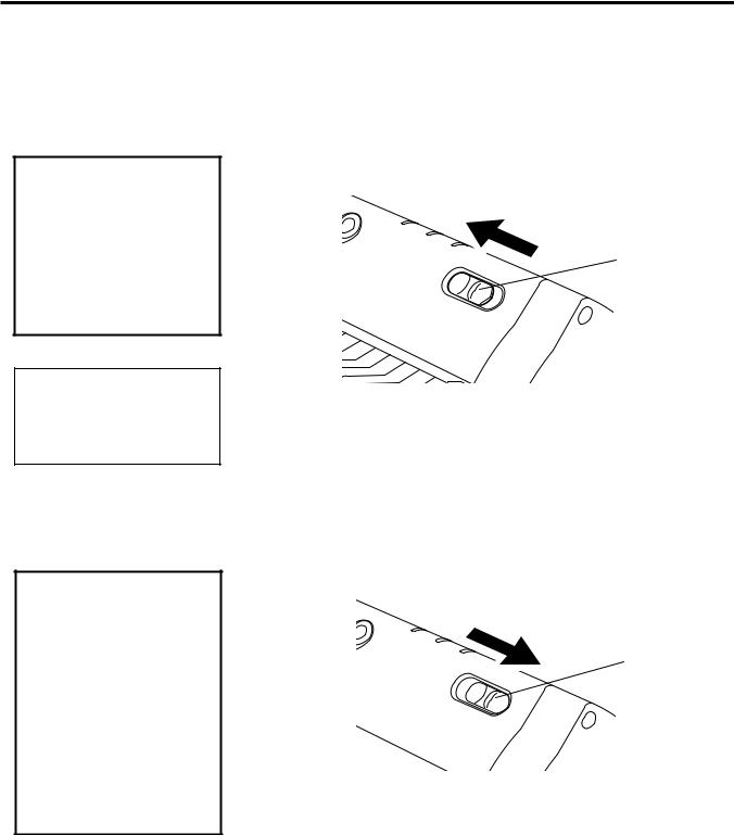
2.5.1 Turning ON the Printer 1. |
To turn ON the printer power, slide the Stand-by switch as shown in |
|
|
the diagram below. Note that ( l ) is the power ON side of the |
|
CAUTION! |
switch. |
|
Use the Stand-by switch |
ON |
|
to turn the printer On/Off. |
||
|
||
Plugging or unplugging |
|
|
the power cord to turn the |
Stand-by Switch |
|
printer On/Off may cause |
|
|
fire, an electric shock, or |
|
|
damage to the printer. |
|
NOTE: |
|
|
|
When the ERROR LED is |
2. |
Check that the ON LINE LED is illuminated. |
|
illuminated, refer to Section |
|||
|
|
4.1LED State.
2.5.2Turning OFF the Printer 1. To turn OFF the printer power, slide the Stand-by switch as shown
CAUTION!
1.Do not turn off the printer power while the media is being printed as this may cause a paper jam or damage to the printer.
2.Do not turn off the printer power while the ON LINE light is blinking as this may cause damage to your computer.
in the diagram below. Note that no mark is printed on the power OFF side.
OFF |
Stand-by Switch |
|
2- 4
2. PRINTER SETUP |
EO1-33030 |
2.6 Opening/Closing the Media Cover
2.6Opening/Closing the Media Cover
WARNING!
The Media Cover should be opened fully. Failure to do this may cause the Media Cover to close by its weight, resulting in injury.
This section describes the opening and closing procedure of the Media Cover. Follow the procedure when cleaning the print head, platen, paper passage, or media sensor, or removing jammed paper.
Opening the Media Cover
1.Release the Media Cover by pushing both sides of the Media Cover Release Catches toward the center, and then open the Media Cover.
Media Cover
Media Cover
Release Catch
Media Cover
Release Catch
Closing the Media Cover
1.Close the Media Cover by pressing portions (A) until they click.
2.Make sure that both Media Cover Release Catches are in position and the Media Cover is locked.
Media Cover
Media Cover
Release Catch
(A)
 Media Cover
Release Catch
(A)
2- 5
2. PRINTER SETUP |
EO1-33030 |
|
2.7 Loading the Media |
|
|
2.7 Loading the Media |
The B-419 printer issues in two issue modes depending on the media |
|
types. |
|
Continuous mode (Fanfold paper) |
∙Insert the media through the media inlet, or open the media cover and set the media, and then close the media cover.
∙When the print command is received from the PC, the specified numbers of media are printed continuously.
∙Pressing the [FEED] button causes one piece of media to be fed.
Cut form mode (When the auto-feed is turned ON.)
∙Insert the media through the media inlet, or open the media cover and set the form, and then close the media cover. The media is automatically fed to the print start position.
∙When the print command is received from the PC, the specified numbers of media are printed one by one.
∙When unprinted data remains after issuing the media, the DATA LED flashes slowly (indicating the printer is waiting for media supply.)
∙Pressing the [FEED] button causes one piece of media to be fed.
2- 6

2. PRINTER SETUP |
EO1-33030 |
2.7 Loading the Media
2.7.1Loading the Fanfold Paper
NOTES:
1.Place the fanfold paper so that the print surface faces up and the top edge of the paper is positioned at the printer side.
Print Surface
Paper Top Edge
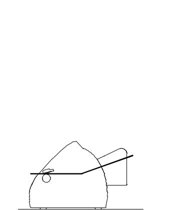
2.Place the fanfold paper on the surface below the position of the printer’s media inlet.
NOTE:
Do not pull the printed paper. Doing so may dislocate the printer or misalign the print position, causing a print failure.
1. Place the fanfold paper at the rear of the printer in line.
Media Inlet
Container
Fanfold Paper
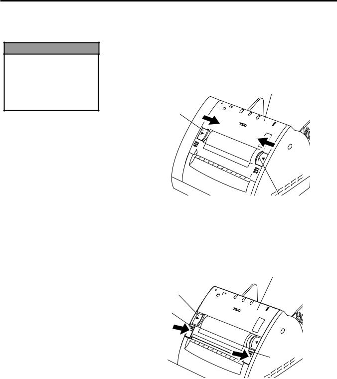
2.Place the paper top edge in front of the Media Inlet, and align the left paper edge with the Paper Guide (L). Push the Paper Guide Release Lever outside, and align the Paper Guide (R) with the right paper edge.
3.Lock the Paper Guide by pulling the Paper Guide Release Lever up.
Paper Guide (L)
Lock
Release
Paper Guide |
|
Release Lever |
Paper Guide (R) |
|
4.Turn the PC power ON, and then turn the printer power ON.
5.Insert the paper top edge into the Media Inlet until it stops. Pressing the [FEED] button feeds one piece of the paper.
6.Send a print data from the PC.
7.The data is printed on the paper. Tear off the printed paper at the edge of the Media Outlet.
2- 7
Loading...