


 Loading...
SERVICE MANUAL
DIGITAL PLAIN PAPER COPIER
8070/6570
5570/4580
GENERAL PRECAUTIONS REGARDING THE INSTALLATION AND SERVICE FOR THE COPIER 6570, 5570
The installation and service should be done by a qualified service technician.
1.Transportation/Installation
•When transporting/installing the copier, move it by the casters while lifting the stoppers.
The copier is quite heavy and weighs approximately 250 kg (551 lb), therefore pay full attention when handling it.
•Be sure to use a dedicated outlet with AC 115V or 120V/20A (220V, 230V, 240V/10A) or more for its power source.
•The copier must be grounded for safety. Never ground it to a gas pipe or a water pipe.
•Select a suitable place for installation.
Avoid excessive heat, high humidity, dust, vibration and direct sunlight.
•Also provide proper ventilation as the copier emits a slight amount of ozone.
•To insure adequate working space for the copying operation, keep a minimum clearance of 80 cm (32”) on the left, 80 cm (32”) on the right and 10 cm (4”) in the rear.
2.Service of Machines
•Basically, be sure to turn the main switch off and unplug the power cord during service.
•Be sure not to touch high-temperature sections such as the exposure lamp, the fuser unit, the damp heater and their periphery.
•Be sure not to touch high-voltage sections such as the chargers, the transfer belt and the highvoltage transformer.
•Be sure not to touch rotating/operating sections such as gears, belts, pulleys, fan, etc.
•When servicing the machines with the main switch turned on, be sure not to touch live sections and rotating/operating sections. Avoid exposure to laser radiation.
•Use suitable measuring instruments and tools.
•Avoid exposure to laser radiation during servicing.
−Avoid direct exposure to beam.
−Do not insert tools, parts, etc. that are reflective into the path of the laser beam.
−Remove all watches, rings, bracelets, etc. that are reflective.
3.Main Service Parts for Safety
•The breaker, door switch, fuse, thermostat, thermofuse, thermistor, etc. are particularly important for safety. Be sure to handle/install them properly.
4.Cautionary Labels
•During servicing, be sure to check the rating plate and the cautionary labels such as “Unplug the power cord during service”, “Hot area”, “Laser warning label” etc. to see if there is any dirt on their surface and whether they are properly stuck to the copier.
5.Disposition of Consumable Parts/Packing Materials
•Regarding the recovery and disposal of the copier, supplies, consumable parts and packing materials, it is recommended to follow the relevant local regulations or rules.
6.When parts are disassembled, reassembly is basically the reverse of disassembly unless otherwise noted in this manual or other related documents. Be careful not to reassemble small parts such as screws, washers, pins, E-rings, toothed washers in the wrong places.
7.Basically, the machine should not be operated with any parts removed or disassembled.
8.Precautions Against Static Electricity
•The PC board must be stored in an anti-electrostatic bag and handled carefully using a wristband, because the ICs on it may become damaged due to static electricity.
Caution: Before using the wrist band, pull out the power cord plug of the copier and make sure that there is no uninsulated charged objects in the vicinity.
Caution |
: |
Dispose of used RAM-IC’s (including lithium battery) |
|
|
according to the manufacturer’s instructions. |
Vorsicht |
: |
Entsorgung des gebrauchten RAM-IC’s (inklusive |
|
|
der Lithium Batterie) nach Angaben des Herstellers. |
|
|
|

1.SPECIFICATIONS • ACCESSORIES • OPTIONS • SUPPLIES
1.1Specifications
•Copy process ................. Indirect electrophotographic process (dry)
•Type ............................... Console type
•Original platen ................ Fixed type (left side, center reference)
•Acceptable originals ....... Sheets, books, and 3-dimensional objects
When the document feeder is used, sheet originals only (60 to 90 g/m2, or 16 lb. to 24 lb.) (without carbon backing, staples and tape) Maximum size: A3 (Ledger)
|
Item |
|
6500/6570 (5500/5570) |
|
4580 |
|
|
8000/8070 |
|
||||
|
Copy speed |
65 cpm (55cpm) |
|
|
45 cpm |
|
|
|
80cpm |
|
|
||
|
PM cycle |
400K (340K) |
|
|
280K |
|
|
|
440K |
|
|
||
|
Region |
NAD, TWD, SAD, ASD, AUD, NAD, ASD, MJD |
|
NAD, TWD, SAD, ASD, AUD |
|||||||||
|
|
MJD, UKD |
|
|
|
|
|
|
MJD, UKD |
|
|||
• Copy speed |
|
|
|
|
|
|
|
|
|
|
(CPM) |
||
|
|
|
|
|
|
|
|
|
|
|
|
|
|
|
Paper |
|
LCF |
|
|
Cassette |
|
|
Manual feeding |
|
|||
|
supply |
|
|
|
|
Size selected |
No size selected |
||||||
|
|
|
|
|
|
|
|
|
|||||
|
Model |
6570 |
|
8070 |
|
6570 |
8070 |
|
6570 |
8070 |
6570 |
8070 |
|
|
|
|
6500 |
|
8000 |
|
6500 |
8000 |
|
6500 |
8000 |
6500 |
8000 |
|
Paper |
|
5570 |
|
|
|
5570 |
|
|
5570 |
|
5570 |
|
|
size |
|
5500 |
|
|
|
5500 |
|
|
5500 |
|
5500 |
|
|
A4, B5, A5-R |
|
65 |
|
80 |
|
65 |
76 |
|
48 |
48 |
33 |
33 |
|
LT, ST-R |
|
55 |
|
|
|
55 |
|
|
48 |
|
33 |
|
|
|
|
45 |
|
|
|
45 |
|
|
45 |
|
25 |
|
|
A4-R, B5-R |
|
— |
|
— |
|
51 |
61 |
|
42 |
42 |
33 |
33 |
|
LT-R |
|
|
|
|
|
45 |
|
|
42 |
|
33 |
|
|
|
|
|
|
|
|
35 |
|
|
35 |
|
25 |
|
|
|
|
|
|
|
|
|
|
|
|
|
|
|
|
B4, FOLIO |
|
— |
|
— |
|
44 |
52 |
|
37 |
37 |
33 |
33 |
|
LG, COMP |
|
|
|
|
|
39 |
|
|
37 |
|
33 |
|
|
|
|
|
|
|
|
30 |
|
|
30 |
|
25 |
|
|
A3, LD |
|
— |
|
— |
|
38 |
43 |
|
33 |
33 |
33 |
33 |
|
|
|
|
|
|
|
34 |
|
|
33 |
|
33 |
|
|
|
|
|
|
|
|
25 |
|
|
25 |
|
25 |
|
* Manually placed originals, one-sided and continuous copy modes
(1) In the models of 6500/6570/5500/5570
*In the case of the automatic document feeder, 65 (55) sheets/minute when an A4 (LT) size single-sided original is fed in the continuous copy mode at original size by the LCF.
*Re-processing speed of automatic duplexing unit .... A4, A5-R, LT, ST-R : 65 (55) sheets/minute
A4-R, LT-R |
: 51 (45) sheets/minute |
LG |
: 44 (39) sheets/minute |
A3, LD |
: 38 (34) sheets/minute |
Note: CPM in a parenthesis is the specification of the 5500/5570. |
|
(2) In the models of 8000/8070 (4580)
*In the case of the automatic documnent feeder, 65 (45) sheets/minute when an A4(LT) size single-sided original is fed in the continuous copy mode at original size by the LCF.
*Re-processing speed of automatic duplexing unit .... A4, A5-R, LT, ST-R : 70 (45) sheets/minute
A4-R, LT-R |
: 57 (35) sheets/minute |
LG |
: 50 (30) sheets/minute |
A3, LD |
: 42 (25) sheets/minute |
Note: CPM in a parenthesis is the specification of the 4580. |
|
Mar. 2000 © TOSHIBA TEC |
11--1A |
8070/6570/5570/4580 SPECIFICATIONS |
• System copy speed |
|
|
|
|
(CPM) |
|
|
|
|
|
|
|
|
Copy mode |
|
6500/6570 |
5500/5570 |
4580 |
8000/8070 |
|
|
|
|
|
|
|
|
Single-sided originals |
1 set |
42 |
38 |
33 |
42 |
|
↓ |
3 sets |
55 |
45 |
41 |
61 |
|
Single-sided copies |
5 sets |
59 |
51 |
42 |
67 |
|
|
|
|
|
|
|
|
Single-sided originals |
1 set |
32 |
28 |
24 |
32 |
|
↓ |
3 sets |
43 |
39 |
33 |
44 |
|
Duplex copies |
5 sets |
48 |
43 |
36 |
49 |
|
|
|
|
|
|
|
|
Two-sided originals |
1 set |
23 |
22 |
17 |
23 |
|
↓ |
3 sets |
39 |
35 |
31 |
40 |
|
Duplex copies |
5 sets |
45 |
41 |
36 |
47 |
|
|
|
|
|
|
|
|
Two-sided originals |
1 set |
28 |
28 |
28 |
28 |
|
↓ |
3 sets |
45 |
42 |
37 |
49 |
|
Single-sided copies |
5 sets |
52 |
46 |
40 |
58 |
|
|
|
|
|
|
|
|
* Ten A4 or LT originals are set in the ADF. This includes the first copy time.
• |
Copy paper |
|
|
|
|
|
|
|
|
|
|
|
|
|
|
|
|
Cassette |
Duplexing |
LCF |
|
Manual feeding |
Note |
|
|
|
|
|
|
|
|
Size |
|
A3 ~ A5-R |
A4, LT |
|
A3 ~ A5-R |
Adjustable to a non- |
|
|
|
|
LD ~ ST-R |
|
|
LD ~ ST-R |
standard size |
|
|
|
|
|
|
|
|
Thickness |
|
64 ~ 80 g/m2 |
|
|
64 ~ 130 g/m2 |
|
|
Special |
|
— |
— |
|
Tracing paper, label |
Our company |
|
paper |
|
|
|
|
paper, OHP film |
recommended |
|
|
|
|
|
|
|
|
|
• |
First copy time |
3.6 seconds max. (A4 or LT, LCF, 100% manually placed original) |
|||||
• |
Warm-up time ................ |
Approx. 420 sec. |
|
|
|
||
• |
Multiple copying ............. |
1 to 999, numerical keypad entry |
|
||||
• |
Reproduction ratio ......... |
Fixed ratio: 100% or 101% (selected in adjustment mode) |
|||||
|
|
|
Zoom ratios: 25 ~ 400% (in 1% steps) |
|
|||
• |
Paper supply .................. |
Automatic feeding: LCF (capacity: 4000 sheets), 3 cassettes (capac- |
|||||
|
|
|
|
|
ity: 500 sheets each), manual bypass feeding (ca- |
||
|
|
|
|
|
pacity: 100 sheets, 64 to 80 g/m2) |
||
|
|
|
Manual feeding: |
64 to 130 g/m2 (80 to 130 g/m2 paper is feed one |
|||
|
|
|
|
|
sheet at a time) |
|
|
• Original capacity (automatic document feeder) |
|
||||||
|
............................ |
|
A4, A4-R, A5-R, LT, LT-R, ST-R: 60 sheets |
|
|||
|
|
|
LG: |
|
|
35 sheets |
|
|
|
|
A3, LD: |
|
|
30 sheets |
|
• Paper capacity (automatic duplexing unit) |
|
|
|
||||
|
............................ |
|
60 sheets (Our company recommended paper 80 g/m2) |
||||
• |
Toner supply .................. |
Automatic density detection and replenishment |
|||||
|
|
|
Toner hopper supply |
|
|||
• |
Exposure control ............ |
Automatic control and manually selectable (11 steps) |
|||||
• |
Weight ............................ |
Copier: 250 kg |
|
|
|
||
8070/6570/5570/4580 SPECIFICATIONS |
11--2A |
Mar. 2000 © TOSHIBA TEC |
• |
Power source ................. |
AC115V/20A, AC 220 • 240V/10A |
||||
• |
Power consumption ....... |
2.0 kW or less |
||||
|
* The power of the automatic document feeder, automatic duplexing unit and LCF is supplied |
|||||
|
from the copier body. |
|
|
|
|
|
• |
Total counter .................. |
Mechanical total counter |
||||
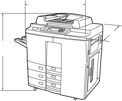
• |
Machine size .................. |
Refer to the figure below |
||||
|
|
|
|
|
|
|
|
|
|
|
920mm |
|
|
|
|
|
|
|
||
742mm
1111mm
*The specifications and external appearance are subject to change without notice in the interest of product improvement.
Mar. 2000 © TOSHIBA TEC |
1 - 3 |
8070/6570/5570/4580 SPECIFICATIONS |
1.2 |
Accessories |
|
|
|
|
|
|
|
|
|
|
|
|
|
Remarks |
|
|
|
|
|
|
|
|
|
Unpacking Instructions |
1 pc. |
|
|
|
|
|
|
|
|
|
|
Operator’s Manual |
1 pc. |
Except MJD |
|
|
|
|
|
|
|
|
|
Drum |
1 pc. |
|
|
|
|
|
|
|
|
|
|
Drum cover |
1 pc. |
|
|
|
|
|
|
|
|
|
|
CS card |
1 pc. |
For MJD |
|
|
|
|
|
|
|
|
|
Sheet CE |
1 pc. |
|
|
|
|
|
|
|
|
|
|
Original feed tray |
1 pc. |
|
|
|
|
|
|
|
|
|
|
Set-up report |
1 set |
For NAD, MJD |
|
|
|
|
|
|
|
|
1.3 |
Options |
|
|
|
|
|
|
|
|
|
|
|
|
DP4580,5570.6570,8070 |
|
DP5500,6500,8000 |
|
|
|
|
|
|
|
|
Finisher |
MJ-1006, MJ-1007 |
|
MJ-1015, MJ1016 |
|
|
|
|
|
|
|
|
Hole punch |
|
— |
|
MJ-6002N |
|
|
|
|
|
MJ-6002E |
|
|
|
|
|
MJ-6002F |
|
|
|
|
|
MJ-6002S |
|
|
|
|
|
|
|
Staple cartridge |
STAPLE-600, STAPLE-700 |
|
||
|
|
|
|
|
|
|
Key counter |
MU-8, MU-10 |
|
||
|
|
|
|
|
|
|
Working tray |
KK-6570 |
|
|
|
|
|
|
|
|
|
1.4 |
Supplies |
|
|
|
|
|
|
|
|
|
|
|
Drum |
OD-6570 |
|
|
|
|
|
|
|
|
|
|
Developer |
D-6570 |
|
|
|
|
|
|
|
|
|
|
Toner bag |
TB-6550, TB-6550E |
|
||
|
|
|
|
|
|
|
Toner |
T-6570, T-6570E |
|
||
|
|
|
|
|
|
8070/6570/5570/4580 SPECIFICATIONS |
1 - 4 |
Mar. 2000 © TOSHIBA TEC |
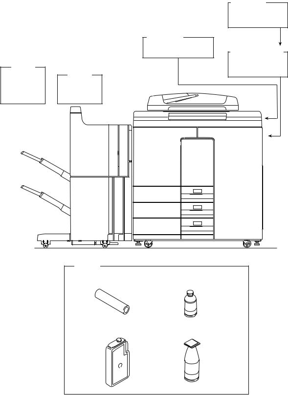
1.5 System List
1) For DP4580/5570/6570/8070
Key counter
MU-10
Working tray
KK-6570
Key counter socket
Staple MU-8
cartridge
Finisher
STAPLE-600  MJ-1016
STAPLE-700 MJ-1017
Supplies
Drum |
Developer |
Toner bag |
Toner |
Mar. 2000 © TOSHIBA TEC |
1 - 5 |
8070/6570/5570/4580 SPECIFICATIONS |
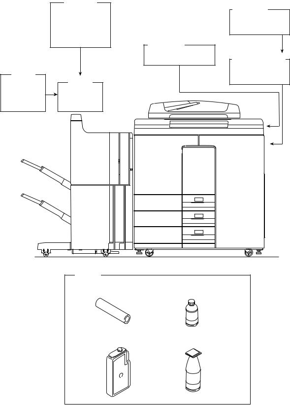
2) For DP5500/6500/8000
Staple cartridge
STAPLE-600
STAPLE-700
Hole punch
Key counter
MJ-6002N
MJ-6002E MU-10 MJ-6002F
MJ-6002S
Working tray
KK-6570
Key counter socket
MU-8
Finisher
MJ-1015
MJ-1016
Supplies
Drum |
Developer |
Toner bag |
Toner |
8070/6570/5570/4580 SPECIFICATIONS |
11--6A |
Mar. 2000 © TOSHIBA TEC |

2.OUTLINE OF THE MACHINE
2.1 Sectional Views and Electrical Parts Location Diagram
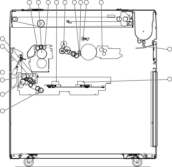
2.1.1Sectional View
[A] Front views of copiers excluding drive systems
1 6
13 |
14 |
10 |
5 |
4 |
3 |
2 |
9 |
12 |
11 |
29 |
31 |
30 |
121 |
|
|
|
|
|
|
|
|
|
|
117 |
112 |
115 |
113 |
116 |
114 |
|
|
|
|
|
|
|
|
|
|
122 |
|
37 |
|
|
|
|
|
|
|
|
|
|
|
|
|
|
49 |
|
|
|
|
109 |
41 |
40 |
39 |
|
|
|
|
|
|
|
|
|
|
|
|
|
|
|
|
|
|
|
|
|
35 |
|
|
48 |
|
|
|
|
|
|
|
|
|
|
50 |
118 |
|
|
|
108 |
|
|
|
|
|
|
|
|
|
|
|
|
|
|
||
51 |
111 |
|
|
|
|
|
|
123 |
|
|
|
|
|
|
|
|
|
|
|
||
|
|
|
|
|
|
|
|
|
|
|
55 |
|
|
119 |
110 |
|
|
|
|
|
|
|
|
|
54 |
|
|
|
|
|
||
|
|
|
|
|
53 |
52 |
|
42 |
44 |
47 |
56 |
|
|
|
|
|
|
|
|||
|
|
|
|
|
|
|
|
|
|
|
57 |
|
|
|
|
|
|
|
|
|
|
58 |
|
|
|
|
|
|
|
64 |
|
|
|
|
|
|
|
|
|
|
|
|
|
59 |
|
|
|
|
|
|
|
|
|
|
60 |
61 |
|
62 |
|
63 |
|
|
|
|
|
105 |
|
|
|
|
|
|
|
|
|
|
104
103
101 |
97 |
99 |
100 |
102 |
|
7 |
34 |
23 |
24 |
|
19 |
|
17 |
15 |
|
8 |
|
|
|
|
|
|
|
|
|
|
|
|
|
|
|
|
|
16 |
|
|
|
|
|
|
|
120 |
|
18 |
|
|
|
|
|
|
|
|
|
|
|
|
|
|
28 |
26 |
|
20 |
|
67 |
32 |
33 |
|
|
|
|
|
|
|
|
|
|
21 |
27 |
25 |
|
|
|
|
66 |
|
|
22 |
|
|
|
|
|
|
|
|
|
|
|
|
|
|
|
|
|
38 |
|
|
|
|
|
|
|
|
68 |
|
|
|
|
|
|
|
|
|
|
36 |
|
|
|
|
|
|
|
|
71 |
|
|
|
|
|
|
|
|
|
|
|
|
|
|
|
|
|
|
|
70 |
|
|
|
74 |
|
|
|
|
|
69 |
|
|
|
|
|
|
|
|
|
72 |
45 |
43 |
46 |
|
|
|
|
|
|
|
|
|
|
|
|
|
|
|
|
73 |
|
|
|
|
|
|
|
|
|
80 |
65 |
|
|
|
|
|
|
|
|
|
|
|
|
|
|
|
|
|
|
82 |
|
|
|
|
|
|
|
|
|
75 |
|
|
|
|
|
|
|
|
|
83 |
|
92 |
|
|
|
|
|
|
|
84 |
|
|
90 |
|
|
|
|
|
|
|
|
|
|
|
|
|
|
|
|
|
|
|
|
|
|
|
|
|
|
76 |
|
|
|
|
|
|
|
|
|
85 |
|
|
|
|
|
|
|
|
|
87 |
|
96 |
94 |
|
93 |
91 |
89 |
107 |
106 |
77 |
Mar. 1999 © TOSHIBA TEC |
2 - 1 |
6570/5570 OUTLINE |
No. |
Name |
No. |
Name |
|
|
|
|
1 |
Carriage 1 |
39 |
Transfer belt |
|
|
|
|
2 |
Mirror 1 |
40 |
Transfer belt drive roller |
|
|
|
|
3 |
Reflector |
41 |
Transfer belt cleaning brush |
|
|
|
|
4 |
Exposure lamp |
42 |
Transfer belt/toner recovery auger |
|
|
|
|
5 |
Thermostat |
43 |
Transfer belt power supply roller |
|
|
|
|
6 |
Carriage 2 |
44 |
Lower damp heater |
|
|
|
|
7 |
Mirror 2 |
45 |
Lower damp heater cover |
|
|
|
|
8 |
Mirror 3 |
46 |
Transfer belt follower roller |
|
|
|
|
9 |
CCD drive PC board |
47 |
Transfer belt separation auxiliary roller |
|
|
|
|
10 |
Scanner control PC board |
48 |
Exit roller |
|
|
|
|
11 |
Lens |
49 |
ADU/eject selector gate |
|
|
|
|
12 |
Original glass |
50 |
ADU/reversal transport roller |
|
|
|
|
13 |
Scanner optical cooling fan |
51 |
ADU/ reversal selector gate |
|
|
|
|
14 |
SLG board cooling fan |
52 |
TR1 sensor |
|
|
|
|
15 |
Toner empty detection lever |
53 |
Empty sensor |
|
|
|
|
16 |
Toner hopper |
54 |
Holding gate |
|
|
|
|
17 |
Toner stirrer lever |
55 |
ADU inlet/reversal roller |
|
|
|
|
18 |
Toner empty switch |
56 |
Separation belt |
|
|
|
|
19 |
Spiral shaft |
57 |
Feed sensor |
|
|
|
|
20 |
Toner transport auger unit |
58 |
Aligning sensor |
|
|
|
|
21 |
Upper magnetic roller |
59 |
ADU/aligning roller |
|
|
|
|
22 |
Lower magnetic roller |
60 |
Feed roller |
|
|
|
|
23 |
Transport roller |
61 |
Pick-up roller |
|
|
|
|
24 |
Leveler |
62 |
Paper transport roller 1 |
|
|
|
|
25 |
Mixer 1 |
63 |
Paper transport roller 2 |
|
|
|
|
26 |
Mixer 2 |
64 |
Paper transport roller 3 |
|
|
|
|
27 |
Supply/recovery paddle |
65 |
Paper transport roller 4 |
|
|
|
|
28 |
Auto-toner sensor |
66 |
Manual pickup roller |
|
|
|
|
29 |
Fur brush |
67 |
Manual feed roller |
|
|
|
|
30 |
Main blade |
68 |
Manual feed separation roller |
|
|
|
|
31 |
Discharge LED |
69 |
LCF paper empty switch (S26)/tray up switch (S39) |
|
|
|
|
32 |
Main charger |
70 |
Manual feed tray |
|
|
|
|
33 |
Main charger wire cleaner |
71 |
LCF feed roller |
|
|
|
|
34 |
Drum |
72 |
LCF pick-up roller |
|
|
|
|
35 |
Toner adhesion sensor |
73 |
LCF separation roller |
|
|
|
|
36 |
Separation claw |
74 |
Aligning roller |
|
|
|
|
37 |
Toner recovery auger |
75 |
Elevator tray |
|
|
|
|
38 |
Recovery blade |
76 |
LCF (large capacity feeder) |
|
|
|
|
6570/5570 OUTLINE |
2 - 2 |
Mar. 1999 © TOSHIBA TEC |
No. |
Name |
No. |
Name |
|
|
|
|
77 |
Tray bottom switch (S40) |
104 |
Middle cassette |
|
|
|
|
80 |
PFP upper aligning roller |
105 |
Upper cassette |
|
|
|
|
82 |
PFP upper feed roller |
106 |
Wire rewind roller |
|
|
|
|
83 |
PFP middle aligning roller |
107 |
Tray motor (M30) |
|
|
|
|
84 |
PFP upper paper switch (S28) |
108 |
Lower heat roller |
|
|
|
|
85 |
PFP upper separation roller |
109 |
Thermostat |
|
|
|
|
87 |
PFP lower aligning roller |
110 |
Cleaning roller 3 |
|
|
|
|
89 |
PFP middle paper start switch (S32) |
111 |
Lower separation claw |
|
|
|
|
90 |
PFP middle separation roller |
112 |
Upper separation claw |
|
|
|
|
91 |
PFP lower paper start switch (S36) |
113 |
Heater lamp |
|
|
|
|
92 |
PFP middle feed roller |
114 |
Upper heat roller |
|
|
|
|
93 |
PFP lower separation roller |
115 |
Cleaning roller 1 |
|
|
|
|
94 |
PFP lower Feed roller |
116 |
Cleaning roller 2 |
|
|
|
|
96 |
PFP lower pick-up roller |
117 |
Exit roller |
|
|
|
|
97 |
Upper elevator |
118 |
Exit switch (S10) |
|
|
|
|
99 |
PFP middle pick-up roller |
119 |
Cleaning roller 4 |
|
|
|
|
100 |
Middle elevator |
120 |
Manual feed inlet fan |
|
|
|
|
101 |
PFP upper pick-up roller |
121 |
System fan |
|
|
|
|
102 |
Lower elevator |
122 |
Laser unit fan |
|
|
|
|
103 |
Lower cassette |
123 |
Transfer belt cleaning blade |
|
|
|
|
Mar. 1999 © TOSHIBA TEC |
2 - 3 |
6570/5570 OUTLINE |
[B]Front Drive System
126 |
127 |
125 |
136 |
128 |
130 |
132 |
129 |
133 |
137
138
131
134
139 |
135 |
140
141
No. |
Name |
No. |
Name |
|
|
|
|
125 |
Cleaning roller 2 |
134 |
Gate solenoid |
|
|
|
|
126 |
Cleaning roller 1 |
135 |
End guide motor (M8) |
|
|
|
|
127 |
Upper heat roller |
136 |
Side guide motor (M9) |
|
|
|
|
128 |
Belt for the toner auger (M15) |
137 |
ADU inlet/reversal roller |
|
|
|
|
129 |
Main cleaning motor (M11) |
138 |
Forward rotation clutch |
|
|
|
|
130 |
Toner recovery auger |
139 |
Reversal clutch |
|
|
|
|
131 |
Toner transport auger |
140 |
Holding gate solenoid |
|
|
|
|
132 |
Fur brush |
141 |
Transport roller clutch |
|
|
|
|
133 |
Transport roller (G23) |
|
|
6570/5570 OUTLINE |
2 - 4 |
Mar. 1999 © TOSHIBA TEC |

[C] Rear Drive System
150
149 |
148 |
146 |
145 |
147 |
208 |
|
|
|
|
|
|
|
205 |
|
|
|
|
|
|
|
|
|
|
|
156 |
153 |
152 |
155 |
154 |
157 |
159 |
158 |
160 |
|
|
|
|
|
|
|
|
|
|
176 |
151 |
|
|
|
|
|
|
|
|
|
200 |
|
|
|
|
|
|
|
175 |
177 |
209 |
|
|
|
|
|
|
|
|
|
|
|
|
|
|
|
|
|
|
|
199 |
|
|
|
|
|
|
|
|
|
198 |
|
|
|
|
|
|
|
|
|
178 |
|
|
|
|
|
|
|
|
|
197 |
|
|
201 |
203 |
202 |
161 |
|
169 |
168 |
|
|
|
|
|
|||||
196 |
|
|
|
|
|
|
|
|
|
195 |
|
|
|
|
|
|
|
|
|
194 |
|
|
|
|
|
|
|
|
|
193 |
|
|
|
|
|
|
174 |
|
|
|
|
|
|
|
|
173 |
172 |
171 |
|
|
|
|
|
|
|
|
|||
192 |
|
|
|
|
|
|
|
|
|
191 |
|
|
|
|
|
|
|
|
|
190 |
|
|
|
|
|
|
|
|
|
189 |
|
|
|
|
|
|
|
|
|
188 |
187 |
204
206
207
163
162
167
164
165
170
166
179
180
181
182
183 184
186
185
Mar. 1999 © TOSHIBA TEC |
2 - 5 |
6570/5570 OUTLINE |
No. |
Name |
No. |
Name |
|
|
|
|
145 |
Scanning motor (M1) |
178 |
Toner transport motor (M15) |
|
|
|
|
146 |
Drive belt |
179 |
PFP upper feed roller |
|
|
|
|
147 |
Drive pulley |
180 |
Upper feed roller clutch (CL6) |
|
|
|
|
148 |
Follower pulley |
181 |
PFP upper separation roller |
|
|
|
|
149 |
Drive wire |
182 |
PFP middle feed roller |
|
|
|
|
150 |
Toner motor (M14) |
183 |
Middle feed roller clutch (CL10) |
|
|
|
|
151 |
Toner transport auger |
184 |
PFP middle separation roller |
|
|
|
|
152 |
Developer motor (M16) |
185 |
Lower feed roller clutch (CL11) |
|
|
|
|
153 |
Paddle |
186 |
PFP lower feed roller |
|
|
|
|
154 |
Upper magnetic roller |
187 |
PFP lower separation roller |
|
|
|
|
155 |
Lower magnetic roller |
188 |
Pedestal motor (M31) |
|
|
|
|
156 |
Mixer |
189 |
Lower aligning roller clutch (CL9) |
|
|
|
|
157 |
Drum motor (M12) |
190 |
PFP lower aligning roller |
|
|
|
|
158 |
Drum pulley (Drum) |
191 |
Middle aligning roller clutch (CL8) |
|
|
|
|
159 |
Drum drive belt |
192 |
PFP middle aligning roller |
|
|
|
|
160 |
Belt transport unit drive motor (M25) |
193 |
Upper aligning roller clutch (CL7) |
|
|
|
|
161 |
Belt transport unit contact/release cam motor (M26) |
194 |
PFP upper aligning roller |
|
|
|
|
162 |
Exit roller |
195 |
LCF separation roller |
|
|
|
|
163 |
ADU/reversal transport roller |
196 |
LCF pick-up roller |
|
|
|
|
164 |
Coupling |
197 |
Feed motor (M32) |
|
|
|
|
165 |
Aligning clutch |
198 |
Manual feed separation roller |
|
|
|
|
166 |
Aligning roller |
199 |
Manual pick-up roller |
|
|
|
|
167 |
ADU motor |
200 |
Manual feed roller |
|
|
|
|
168 |
Feed clutch |
201 |
LCF feed roller |
|
|
|
|
169 |
Separation belt |
202 |
Aligning rollers |
|
|
|
|
170 |
Feed roller |
203 |
Aligning motor (M17) |
|
|
|
|
171 |
Paper transport roller 1 |
204 |
Slot exhaust fan (M23) |
|
|
|
|
172 |
Paper transport roller 2 |
205 |
Exit fan (M19) |
|
|
|
|
173 |
Paper transport roller 3 |
206 |
Heater fan (M20) |
|
|
|
|
174 |
Paper transport roller 4 |
207 |
Reversal fan (M27) |
|
|
|
|
175 |
Upper heat roller pulley |
208 |
Duct in fan (M22) |
|
|
|
|
176 |
Fuser drive belt |
209 |
Developer fan (M23) |
|
|
|
|
177 |
Heat roller motor (M18) |
|
|
|
|
|
|
6570/5570 OUTLINE |
2 - 6 |
Mar. 1999 © TOSHIBA TEC |

[D] Sectional View of Automatic Document Feeder
23


 22 24
22 24


26 25


1
2
3
4

6

5
21
 20
20
 18
18
 19
19
 16
16
 18
18
17
16 
 15
15  14
14  13 12
13 12  10
10
11
7 |
8 |
9 |
Name |
APS switch |
Belt follower roller |
Reversal roller |
Exit sensor |
Exit cover switch |
Flapper |
Exit roller |
Transport belt cleaning brush |
|
|
|
|
|
|
|
|
|
No. |
19 |
20 |
21 |
22 |
23 |
24 |
25 |
26 |
|
|
|
|
|
|
|
|
|
Name |
|
|
|
|
|
|
|
|
|
|
Timing sensor |
Aligning roller |
Feed roller |
Belt drive roller |
Belt drop roller |
DF open switch |
Belt holding roller |
Transport belt |
Belt holding roller |
|
|
|
|
|
|
|
|
|
|
No. |
10 |
11 |
12 |
13 |
14 |
15 |
16 |
17 |
18 |
|
|
|
|
|
|
|
|
|
|
Name |
Pick-up roller |
Weight |
Empty sensor lever |
Empty sensor |
Separation pad |
Feed cover switch |
Aligning sensor |
Size sensor |
Size sensor lever |
|
|
|
|
|
|
|
|
|
|
No. |
1 |
2 |
3 |
4 |
5 |
6 |
7 |
8 |
9 |
Mar. 1999 © TOSHIBA TEC |
2 - 7 |
6570/5570 OUTLINE |
2.1.2Electrical parts layout
[A] Configuration of Units
|
unit |
unit |
Scanner |
|
|
|
Laser |
unit Upper
|
U |
A |
D |
|
unit Lower
unit System
Rear side
6570/5570 OUTLINE |
2 - 8 |
Mar. 1999 © TOSHIBA TEC |

[B] Scanner Unit
(B-1) PC board
2
1
|
|
3 |
|
|
Scanner unit |
|
|
|
|
Rear side |
|
|
|
|
|
No. |
Name |
|
Symbol |
1 |
CCD drive PC board (PWA-F-CCD-300) |
|
CCD |
2 |
Scanning optical system control PC board (PWA-F-SLG-300) |
|
SLG |
3 |
Scanning motor drive PC board (PWA-F-SDV-300) |
|
SDV |
|
|
|
|
Mar. 1999 © TOSHIBA TEC |
2 - 9 |
6570/5570 OUTLINE |

(B-2) DC electrical parts (except motors, PC boards)
[A4 series]
1
2
Scanner unit
|
|
Rear side |
|
|
|
|
|
No. |
Name |
|
Symbol |
1 |
Automatic paper size detector (APS1-6) |
|
S1-6 |
2 |
Home switch (HOME-SW) |
|
S2 |
|
|
|
|
[LT series]
1
2
Scanner unit
|
|
Rear side |
|
|
|
|
|
No. |
Name |
|
Symbol |
1 |
Automatic paper size detector (APS1-4) |
|
S1-4 |
2 |
Home switch (HOME-SW) |
|
S2 |
|
|
|
|
6570/5570 OUTLINE |
2 - 10 |
Mar. 1999 © TOSHIBA TEC |

(B-3) Motors
3
4
|
|
2 |
|
|
|
1 |
|
|
Scanner unit |
|
|
|
|
Rear side |
|
|
|
|
|
No. |
Name |
|
Symbol |
1 |
Scanning motor (SCN-MOT) |
|
M1 |
2 |
Document motor (DCM-MOT) |
|
M2 |
3 |
Scanning optical system cooling fan motor (OPT-FAN-MOT) |
|
M3-1,-2 |
4 |
SLG PC board cooling fan motor (SLG-FAN-MOT) |
|
M4 |
|
|
|
|
(B-4) AC electrical parts
6
5
4
2
1
3
Scanner unit
Rear side
7
No. |
Name |
Symbol |
1 |
Damp heater (M) (D-HTR-M) |
DHM |
2 |
Damp heater (L) (D-HTR-L) |
DHL |
3 |
Fuse PC board (PWA-F-FUS-351) |
FUS |
5 |
Thermostat (85°C) |
THMO |
6 |
Exposure lamp (EXPO-LAMP) (EXP) |
EXP |
7 |
Lamp regulator PC board (PS-LRG-300) |
LRG |
|
|
|
Mar. 1999 © TOSHIBA TEC |
2 - 11 |
6570/5570 OUTLINE |
[C] Laser Unit
(C-1) PC boards
2
3
4
4
|
|
|
1 |
|
|
Laser unit |
4 |
|
|
|
|
|
|
|
|
|
|
Rear side |
|
|
|
4 |
|
|
|
|
|
|
|
No. |
Name |
|
|
Symbol |
1 |
PLG PC board (PWA-F-PLG-300) |
|
|
PLG |
2 |
Polygon mirror motor drive PC board (M/A-DRV-POL-300) |
|
POL |
|
3 |
Sensor PC board (PWA-F-SNS-300) |
|
|
SNS |
4 |
Laser PC board (K-PWA-F-LDR-300) |
|
|
LDR |
|
|
|
|
|
(C-2) Electrical parts (except motors, PC boards)
1
1
1
|
Laser unit |
1 |
|
|
|
|
|
Rear side |
|
|
|
|
|
|
No. |
|
Name |
|
Symbol |
1 |
|
Galvanomirror (ASM-GALVA) |
|
GLV |
6570/5570 OUTLINE |
2 - 12 |
Mar. 1999 © TOSHIBA TEC |

(C-3) Motors
2 |
1 |
|
Laser unit
|
|
Rear side |
|
|
|
|
|
No. |
Name |
|
Symbol |
1 |
Polygon mirror motor (POL-MOT) |
|
M5 |
2 |
Laser unit fan (LSU-FAN-MOT) |
|
M6 |
|
|
|
|
[D] System Unit
(D-1) PC boards
System unit
4
1
2
|
|
|
3 |
|
|
|
|
Rear side |
|
|
|
5 |
|
|
|
|
|
|
|
No. |
Name |
|
|
Symbol |
1 |
System PC board (PWA-F-SYS-300) |
|
|
SYS |
2 |
Mother board (PWA-F-MTB-300) |
|
|
MTB |
3 |
Hard disk (HDD) |
|
|
HDD |
4 |
LAN printer board or SCSI board (option) |
|
|
LAN or SCSI |
5 |
NIC board (option for LAN printer board) |
|
|
NIC |
|
|
|
|
|
Mar. 1999 © TOSHIBA TEC |
2 - 13 |
6570/5570 OUTLINE |
(D-2) Motor
1
System unit
|
|
Rear side |
|
|
|
|
|
No. |
Name |
|
Symbol |
1 |
System fan motor (FAN-SYS) |
|
M7 |
|
|
|
|
[E] ADU |
|
|
|
(E-1) PC board
1
Rear side
ADU
No. |
Name |
Symbol |
1 |
ADU PC board (PWA-F-ADU-300) |
ADU |
|
|
|
6570/5570 OUTLINE |
2 - 14 |
Mar. 1999 © TOSHIBA TEC |

(E-2) DC electrical parts (except motors, PC boards)
7 |
8 |
9 |
10 |
|
6
5
4
3
|
11 |
2 |
12 |
|
|
1 |
13 |
|
ADU |
Rear side |
No. |
Name |
Symbol |
1 |
Transport switch (TR2-SW) |
S3 |
2 |
End switch (END-SW) |
S4 |
3 |
Transport switch 1 (TR1-SW) |
S5 |
4 |
Transport clutch (TR-CLT) |
CL1 |
5 |
Reverse clutch (REV-CLT) |
CL2 |
6 |
Guide solenoid (GID-SOL) |
SOL1 |
7 |
Stack clutch (STK-CLT) |
CL3 |
8 |
Feed switch (FED-SW) |
S6 |
9 |
Empty switch (EMP-SW) |
S7 |
10 |
Aligning switch (RGT-SW) |
S8 |
11 |
Aligning clutch (RGT-CLT) |
CL4 |
12 |
Feed clutch (FED-CLT) |
CL5 |
13 |
Side switch (SID-SW) |
S9 |
Mar. 1999 © TOSHIBA TEC |
2 - 15 |
6570/5570 OUTLINE |
(E-3) Motors
1
2
Rear side
ADU
No. |
Name |
Symbol |
1 |
End guide motor (END-MOT) |
M8 |
2 |
Side guide motor (SID-MOT) |
M9 |
|
|
|
6570/5570 OUTLINE |
2 - 16 |
Mar. 1999 © TOSHIBA TEC |

[F] Upper Unit
(F-1) PC board
1
Upper unit |
Rear side |
No. |
Name |
Symbol |
1 |
Motor control PC board (PWA-F-MOT-300) |
MOT |
|
|
|
Mar. 1999 © TOSHIBA TEC |
2 - 17 |
6570/5570 OUTLINE |

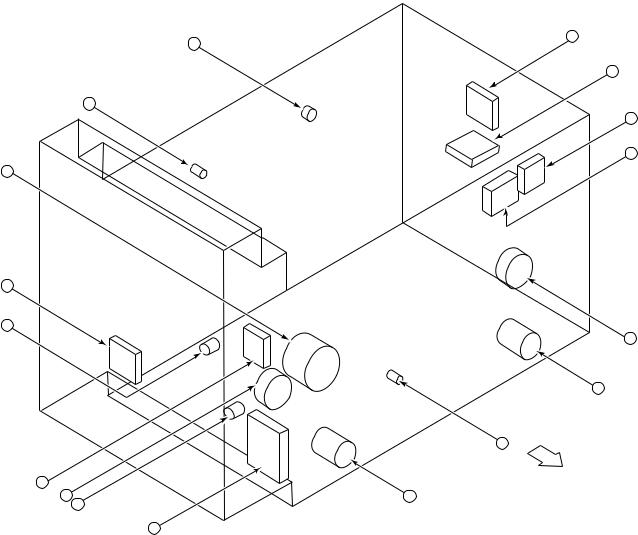
(F-2) DC electrical parts (except motors, PC boards)
1
2 |
21
3
4
5
17
14
13
10 |
15 |
6
19
18
16
9
20
Upper unit |
12 7 |
11 |
Rear side |
|
8 |
No. |
Name |
Symbol |
1 |
Fuser exit switch (EXIT-SW) |
S10 |
2 |
Scraper solenoid (SOL3) |
SOL3 |
3 |
Toner supply sensor (TNR-HOP-SW) |
S11 |
4 |
Auto toner sensor (SNR-ATC-300) |
ATS |
5 |
Toner empty sensor (TNR-EMP-SW) |
S12 |
6 |
Paper stop switch (P-STP-SW) |
S13 |
7 |
Developer switch (DEV-SW) |
S14 |
8 |
Toner full switch (T-FULL-SW) |
S15 |
9 |
Main cleaning switch (CLN-M-SW) |
S16 |
10 |
Heat roller thermistor (THMS-HTR-300) |
THMSH |
11 |
Developer bias transformer (PS-HVT-DB-300) |
HVT-DB |
12 |
High-voltage power supply for main charger and transfer belt (PS-HVT-TM-300) |
HVT-TM |
13 |
Reversal exit switch (TRNE-SW) |
S17 |
14 |
Reversal switch (TRN-SW) |
S18 |
15 |
Reversal door switch (EXC-SW) |
S19 |
16 |
Discharge LED lamp (ERS-300) |
ERS |
17 |
Gate solenoid (GATE-SOL) |
SOL4 |
18 |
Transfer belt touch switch (IR-TCH-SW) |
S43 |
19 |
Transfer belt separation switch (TR-SEP-SW) |
S44 |
20 |
Toner adhesion sensor |
IQM |
21 |
Drum thermister |
THMSD |
6570/5570 OUTLINE |
2 - 18 |
Mar. 1999 © TOSHIBA TEC |
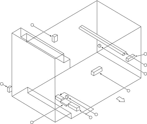
(F-3) Motors
11
1
18
2 |
14 |
10
3
4 |
5 |
9
15
13
7
6
Upper unit |
12 |
|
16
Rear side
8 |
No. |
Name |
Symbol |
1 |
Fur brush motor (FUR-MOT) |
M10 |
2 |
Main cleaning motor (CLN-MOT) |
M11 |
3 |
Drum motor (DRM-MOT) |
M12 |
4 |
Manual inlet fan motor (SFB-FAN-MOT) |
M13 |
5 |
Toner motor (TNR-MOT) |
M14 |
6 |
Toner transport motor (AUG2-MOT) |
M15 |
7 |
Developer motor (DEV-MOT) |
M16 |
8 |
Aligning motor (RGT-MOT) |
M17 |
9 |
Heat roller motor (HTR-MOT) |
M18 |
10 |
Exit fan motor (EXIT-FAN-MOT) |
M19 |
11 |
Heater fan motor (HTR-FAN-MOT) |
M20 |
12 |
Developer fan motor (DEV-FAN-MOT) |
M21 |
13 |
Duct in fan motor (DUCT-IN-FAN-MOT) |
M22 |
14 |
Duct out fan motor (DUCT-OUT-FAN-MOT) |
M23 |
15 |
ADU motor (ADU-MOT) |
M24 |
16 |
Transfer belt motor (TRB-MOT) |
M25 |
17 |
Transfer belt cam motor (TRB-CAM-MOT) |
M26 |
18 |
Reversal fan motor (REV-FAN-MOT) |
M27 |
Mar. 1999 © TOSHIBA TEC |
2 - 19 |
6570/5570 OUTLINE |
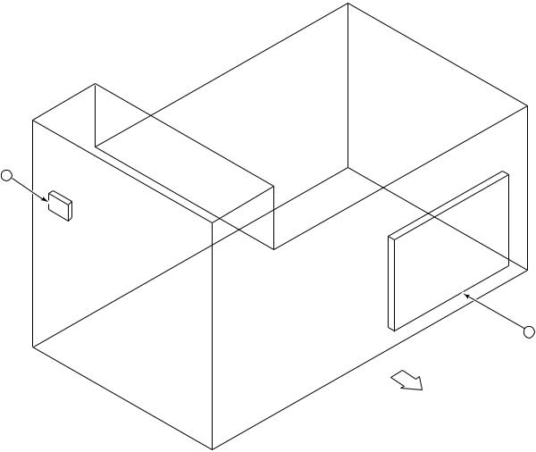
(F-4) AC electrical parts
1 |
8
6
7
2
9
Rear side
Upper unit
5
4
3 |
No. |
Name |
Symbol |
1 |
Door switch (DOOR-SW) |
S41 |
2 |
Main switch (MAIN-SW) |
S42 |
3 |
Fuse PC board (PWA-F-FUS-351) |
FUS |
4 |
Damp heater (lower) (D-HTR-L) |
DHL-1,-2 |
5 |
Thermostat |
THM-D |
6 |
Heater lamp (HTR-LAMP) |
HTR-L |
7 |
Fuser thermostat (THERMO-152-FUS) |
THM-F |
8 |
EXIT door switch (EXIT-AC-SW) |
S45 |
9 |
Fuser switch (HTR-SW) |
S46 |
6570/5570 OUTLINE |
2 - 20 |
Mar. 1999 © TOSHIBA TEC |
[G] Lower Unit
(G-1) PC boards
2
1
Lower unit |
Rear side |
No. |
Name |
Symbol |
1 |
Logic PC board (PWA-F-LGC-300) |
LGC |
2 |
LCF PC board (PWA-F-LCF-150) |
LCF |
Mar. 1999 © TOSHIBA TEC |
2 - 21 |
6570/5570 OUTLINE |
Loading...