


65HM117
57HM117_EN.book Page 1 Friday, March 23, 2007 9:48 AM
Integrated High Definition
®
DLP
Projection Television
HIGH-DEFINITION TELEVISION
57HM117
65HM117
For an overview of steps for setting up your new TV, see page 10.
Note: To display a High Definition picture, the TV must be receiving a
High Definition signal (such as an over-the-air High Definition TV
broadcast, a High Definition digital cable program, or a High Definition
digital satellite program). For details, please contact your TV antenna
installer, cable provider, or satellite provider.
Note: If the TV is powered off and then quickly on again when the
lamp unit is hot, it may take several minutes for the picture to appear
on-screen. This is a property of DLP
a sign of malfunction. For details, see "IMPORTANT NOTICE ABOUT
HOT LAMP RESTART" on page 6.
© 2007 TOSHIBA CORPORATION
All Rights Reserved
®
TV lamp technology and is NOT
Owner’s Record
The model number and serial number are on the back of
your TV. Record these numbers in the spaces below.
Refer to these numbers whenever you communicate
with your Toshiba dealer about this TV.
Model number:
Serial number:
YC/N
VX1A00046100
HM117 (E/F) Web 213:276
57HM117_EN.book Page 2 Friday, March 23, 2007 9:48 AM
Dear Customer,
Thank you for purchasing this Toshiba TV. This manual will
help you use the many exciting features of your new TV. Before
operating the TV, please read this manual completely, and
keep it nearby for future reference.
Safety Precautions
WARNING: TO REDUCE THE RISK OF FIRE OR
ELECTRIC SHOCK, DO NOT EXPOSE THIS APPLIANCE
TO RAIN OR MOISTURE.
This is a reminder to call the CATV system installer’s attention
to Article 820-40 of the U.S. NEC, which provides guidelines for
proper grounding and, in particular, specifies that the cable
ground shall be connected to the grounding system of the building,
as close to the point of cable entry as practical. For additional
CAUTION: This television is for use only with
the supplied Toshiba stand (- page 66). Use
with other carts or stands is capable of resulting in
instability, causing possible injury.
NOTE TO CATV INSTALLERS IN THE U.S.A.
antenna grounding information, see items 28 and 29 on page 4.
WARNING
RISK OF ELECTRIC SHOCK
DO NOT OPEN.
Child Safety
It Makes A Difference
WARNING: TO REDUCE THE RISK OF ELECTRIC SHOCK,
DO NOT REMOVE COVER (OR BACK). NO USERSERVICEABLE PARTS INSIDE. REFER SERVICING TO
(This does not apply to “Lamp
QUALIFIED SERVICE PERSONNEL.
unit replacement and care” in Chapter 9.)
The lightning flash with arrowhead symbol, within an
equilateral triangle, is intended to alert the user to the
presence of uninsulated “dangerous voltage” within
the product’s enclosure that may be of sufficient
magnitude to constitute a risk of electric shock to
persons.
The exclamation point within an equilateral triangle is
intended to alert the user to the presence of important
operating and maintenance (servicing) instructions in
the literature accompanying the appliance.
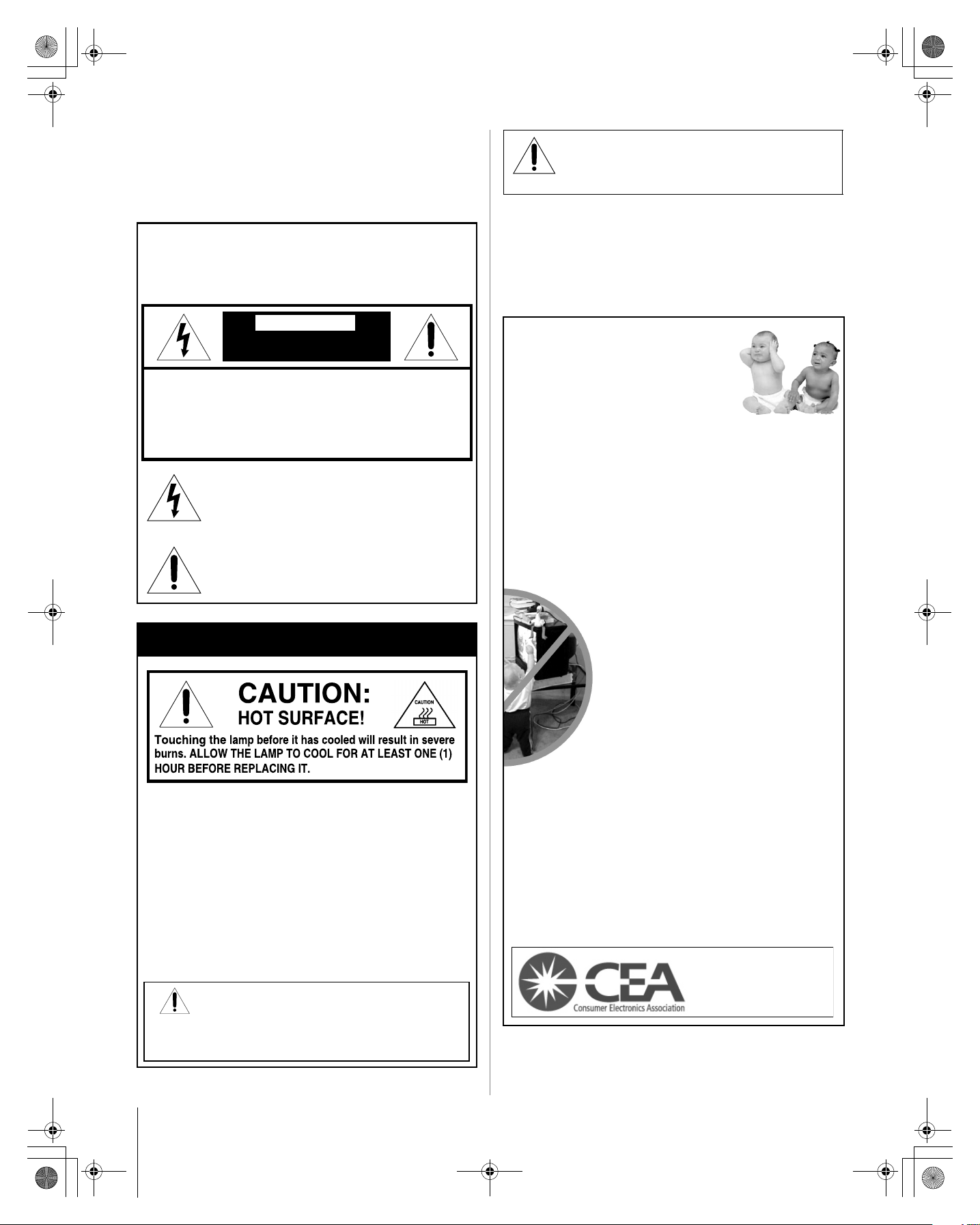
Where Your TV Stands
Congratulations on your purchase!
As you enjoy your new TV, keep these safety tips in mind:
The Issue
a If you are like most consumers, you have a TV in your home.
Many homes, in fact, have more than one TV.
The home theater entertainment experience is a growing trend,
a
and larger TVs are popular purchases; however, they are not
always supported on the proper TV stands.
a Sometimes TVs are improperly secured or inappropriately
situated on dressers, bookcases, shelves, desks, audio
speakers, chests, or carts. As a result, TVs may fall over,
causing unnecessary injury.
Toshiba Cares!
a The consumer electronics industry
Lamp Unit Replacement
is committed to making home entertainment
enjoyable and safe.
The Consumer Electronics Association
a
formed the Home Entertainment Support
Safety Committee, comprised of TV and
consumer electronics furniture
manufacturers, to advocate children’s safety
and educate consumers and their families
about television safety.
The lamp in this product has a limited service life. The length
of service life varies depending on product use and user
settings. If you use the lamp beyond its service life:
• you may notice a reduction in the colors and/or brightness
of the picture, at which time you should replace the lamp
unit; and
• the strength of the quartz glass in the lamp will be reduced
and the lamp may rupture. If the lamp ruptures, the TV will
not operate until the lamp unit is replaced.
Dispose of the used lamp unit by the approved method for
your area.
See “Lamp unit replacement and care”
in Chapter 9.
Note: The lamp unit contains mercury.
Disposal of mercury may be regulated due to
environmental considerations. For disposal or recycling
information, contact your local authorities or the Electronic
Industries Alliance (www.eiae.org).
2
Tune Into Safety
a One size does NOT fit all! Use appropriate furniture
large enough to support the weight of your TV (and other
electronic components).
Use appropriate angle braces, straps, and anchors to secure your
a
furniture to the wall (but never screw anything directly into the TV).
a Carefully read and understand the other enclosed
instructions for proper use of this product.
a Do not allow children to climb on or play with furniture and TVs.
a Avoid placing any item on top of your TV (such as a VCR, remote
control, or toy) that a curious child may reach for.
a Remember that children can become excited while watching
a program and can potentially push or pull a TV over.
a Share our safety message about this hidden hazard of the home
with your family and friends. Thank you!
2500 Wilson Blvd.
Arlington, VA 22201 U.S.A.
www.CE.org
CEA is the Sponsor, Producer and
Manager of the International CES
®
HM117 (E/F) Web 213:276
57HM117_EN.book Page 3 Friday, March 23, 2007 9:48 AM
Important Safety Instructions
1) Read these instructions.
2) Keep these instructions.
3) Heed all warnings.
4) Follow all instructions.
5) Do not use this apparatus near water.
6) Clean only with dry cloth.
7) Do not block any ventilation openings. Install in
accordance with the manufacturer’s instructions.
8) Do not install near any heat sources such as radiators,
heat registers, stoves, or other apparatus (including
amplifiers) that produce heat.
9) Do not defeat the safety purpose of
the polarized or grounding type
plug. A polarized plug has two blades
with one wider than the other.
A grounding type plug has two blades
and a third grounding prong. The wide blade or the third
prong are provided for your safety. If the provided plug
does not fit into your outlet, consult an electrician for
replacement of the obsolete outlet.
10) Protect the power cord from being walked
on or pinched, particularly at plugs,
convenience receptacles, and the point
where they exit from the apparatus.
11) Only use attachments/accessories specified by the
manufacturer.
12) Use only with the cart, stand, tripod,
bracket, or table specified by the
manufacturer, or sold with the
apparatus. When a cart is used, use
caution when moving the cart/apparatus
combination to avoid injury from tip-over.
13) Unplug this apparatus during lightning storms or
when unused for long periods of time.
14) Refer all servicing to qualified service personnel.
Servicing is required when the apparatus has been
damaged in any way, such as power-supply cord or plug
is damaged, liquid has been spilled or objects have fallen
into the apparatus, the apparatus has been exposed to
rain or moisture, does not operate normally, or has been
dropped.
Additional Safety Precautions
14a) Item 14 does not apply to “Lamp unit replacement and
care” in Chapter 9.
14b) CAUTION: If the TV is dropped and the cabinet or
enclosure surface has been damaged or the TV does
not operate normally, take the following precautions:
• ALWAYS turn off the TV and unplug the power cord to
avoid possible electric shock or fire.
• To prevent personal injury, never handle the damaged
television.
• ALWAYS contact a service technician to inspect the TV
any time it has been damaged or dropped.
Wide blade
15) CAUTION:
• To reduce the risk of electric shock, do not use the
polarized plug with an extension cord, receptacle, or
other outlet unless the blades can be inserted
completely to prevent blade exposure.
• To prevent electric shock, match wide blade of plug to
wide slot; fully insert.
16) WARNING: This product contains a lamp to project
the picture, and requires special safety precautions:
• See Chapter 9 for instructions on lamp unit replacement
and care.
• DO NOT attempt to service this product except as
specified in the “Lamp unit replacement and care”
section in Chapter 9. The only user-serviceable item in
this product is the lamp unit.
17) WARNING:
To prevent the spread of fire, keep candles or other open
flames away from this product at all times.
Installation, Care, and Service
Installation
Follow these recommendations and precautions and heed all
warnings when installing your TV:
18) Never modify this equipment. Changes or modifications
may void: a) the warranty, and b) the user’s authority to
operate this equipment under the rules of the Federal
Communications Commission.
19) DANGER: RISK OF
SERIOUS PERSONAL
INJURY, DEATH, OR
EQUIPMENT DAMAGE!
Never place the TV on an unstable cart,
stand, or table. The TV may fall, causing
serious personal injury, death, or serious
damage to the TV.
20) Never place or store the TV in direct sunlight; areas
subject to excessive dust or vibration; or locations with
temperatures at or below 41°F (5°C). See “Specifications”
section on page 66 on operating conditions.
21) Always place the TV on the TV stand provided with the TV
or on a sturdy, level, stable surface that can safely support
the size and weight of the unit. See “Notice of possible TV
stand instability” and “Child Safety” on page 2.
22) The apparatus shall not be exposed to dripping or
splashing and that no objects filled with liquids, such as
vases, shall be placed on the apparatus.
23) Always place the back of the television at least four (4)
inches away from any vertical surface (such as a wall) to
allow proper ventilation.
(continued)
3
HM117 (E/F) Web 213:276
57HM117_EN.book Page 4 Friday, March 23, 2007 9:48 AM
24) Never block or cover the slots or openings in the TV
cabinet back, bottom, and sides. Never place the TV:
• on a bed, sofa, rug, or similar surface;
• too close to drapes, curtains, or walls; or
• in a confined space such as a bookcase, built-in
cabinet, or any other place with poor ventilation.
The slots and openings are provided to protect the TV
from overheating and to help maintain reliable operation of
the TV.
25) Never allow anything to rest on or roll over the power cord,
and never place the TV where the power cord is subject to
wear or abuse.
26) Never overload wall outlets and extension cords.
27) Always operate this equipment from a 120 VAC, 60 Hz
power source only.
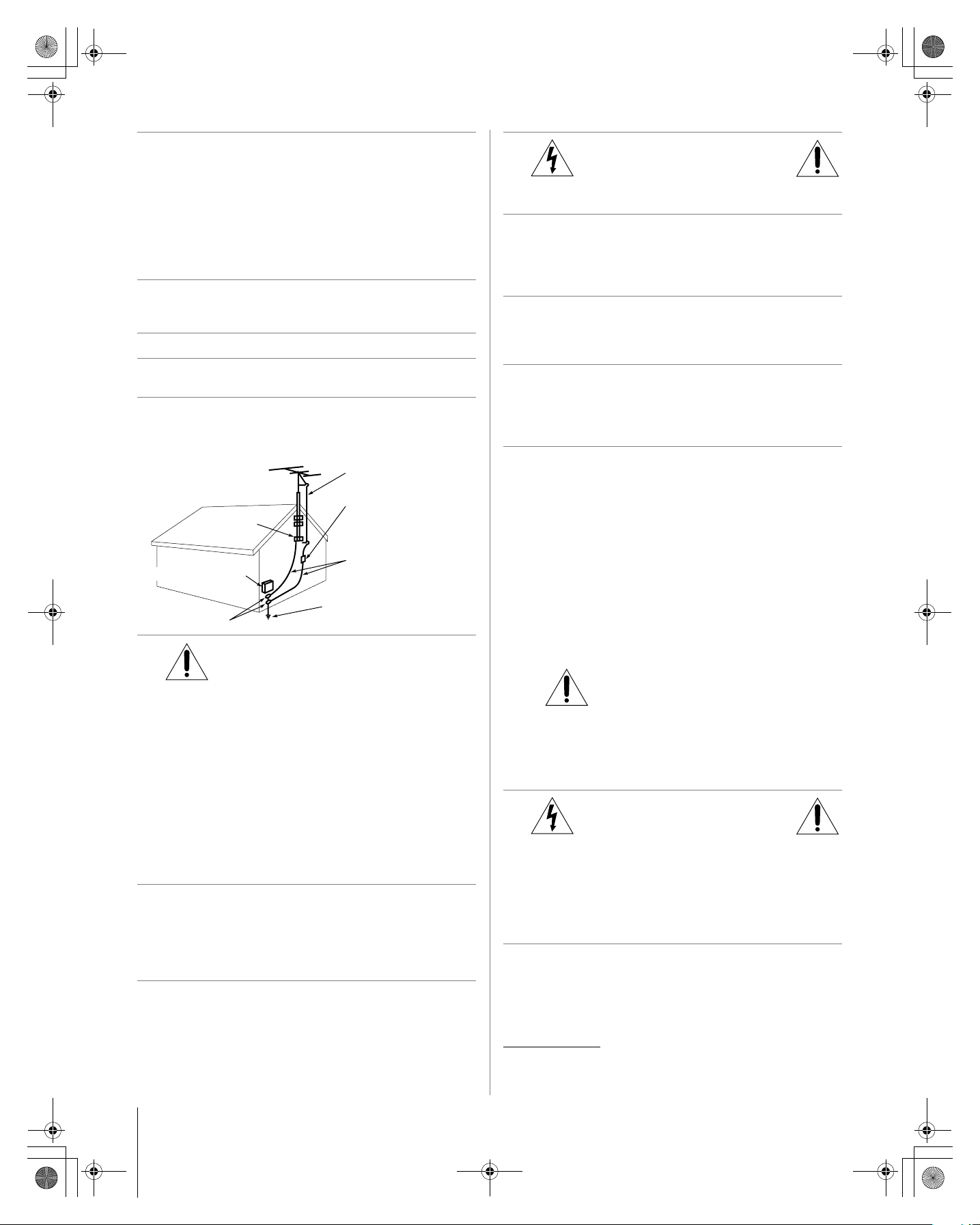
28) Always make sure the antenna system is properly
grounded to provide adequate protection against voltage
surges and built-up static charges (see Section 810 of the
National Electric Code).
Antenna lead-in wire
Antenna discharge unit
Ground clamp
Electric service equipment
Ground clamps
29)
DANGER: RISK OF SERIOUS
(NEC Section 810-20)
Grounding conductors
(NEC Section 810-21)
Power service grounding
electrode system (NEC Art 250 Part-H)
PERSONAL INJURY OR DEATH!
• Use extreme care to make sure you are never in a
position where your body (or any item you are in contact
with, such as a ladder or screwdriver) can accidentally
touch overhead power lines. Never locate the antenna
near overhead power lines or other electrical circuits.
• Never attempt to install any of the following during
lightning activity: a) an antenna system; or b) cables,
wires, or any home theater component connected to an
antenna or phone system.
Care
For better performance and safer operation of your TOSHIBA
TV, follow these recommendations and precautions:
30) Always sit approximately 10–25 feet away from the TV and
as directly in front of it as possible. The picture can appear
dull if you sit too far to the left or right of the TV, or if
sunlight or room lights reflect on the screen. Turn the TV
off to check for reflections on the screen, and then remove
the source of reflections while viewing the TV.
31) Always unplug the TV before cleaning. Never use liquid or
aerosol cleaners. Clean only with a soft, dry cloth. Do not
spray volatile compounds, such as insecticide, on the
cabinet. This may discolor or damage the cabinet.
32)
WARNING:
RISK OF ELECTRIC SHOCK!
Never spill liquids or push objects of any kind into the TV
cabinet slots.
33) If the air temperature rises suddenly (for example, when
the TV is first delivered), condensation may form on the
lenses. This can make the picture appear distorted or the
color appear faded. If this happens, turn off the TV for 6 to
7 hours to allow the condensation to evaporate.
34) For added protection of your TV from lightning and power
surges, always unplug the power cord and disconnect the
antenna from the TV if you leave the TV unattended or
unused for long periods of time.
35) During normal use, the TV may make occasional snapping
or popping sounds. This is normal, especially when the
unit is being turned on or off. If these sounds become
frequent or continuous, unplug the power cord and contact
a Toshiba Authorized Service Center.
36) Special care for DLP® (Digital Light Processing) units:
• The lamp unit in this product has a limited service life.
The length of service life varies depending on product
use or user settings. If you use the lamp beyond its
service life:
• you may notice a reduction in the colors and/or
brightness of the picture, at which time you should
replace the lamp unit; and
• the strength of the quartz glass in the lamp will be
reduced and the lamp may rupture. If the lamp ruptures,
the TV will not operate until the lamp unit is replaced.
See “Lamp unit replacement and care” in Chapter 9.
• Dispose of the used lamp unit by the approved method
for your area.
• The lamp unit contains mercury. Disposal of
mercury may be regulated due to
environmental considerations. For disposal or
recycling information, please contact your
local authorities or the Electronic Industries
Alliance (www.eiae.org).
Service
37)
RISK OF ELECTRIC SHOCK!
Never attempt to service the TV yourself, except as
specified in the “Lamp unit replacement and care” section
in Chapter 9. Opening and removing the covers may
expose you to dangerous voltage or other hazards. Failure
to follow this WARNING may result in death or serious
injury. Refer all servicing not specified in this manual to a
Toshiba Authorized Service Center.
38) If you have the TV serviced:
• Ask the service technician to use only replacement
parts specified by the manufacturer.
• Upon completion of service, ask the service technician
to perform routine safety checks to determine that the
TV is in safe operating condition.
DLP® and the DLP logo are registered trademarks of Texas
Instruments.
WARNING:
4
HM117 (E/F) Web 213:276
57HM117_EN.book Page 5 Friday, March 23, 2007 9:48 AM
39) When the TV reaches the end of its useful life, ask a
qualified service technician to properly dispose of the TV.
Note: The lamp unit contains mercury. Disposal of
mercury may be regulated due to environmental
considerations. Dispose of the used lamp unit by the
approved method for your area.
For disposal or recycling information, please contact your
local authorities or the Electronic Industries Alliance
(www.eiae.org).
FCC Declaration of Conformity
Compliance Statement
(Part 15):
The Toshiba 57HM117 and 65HM117 Televisions comply
with Part 15 of the FCC rules.
Operation is subject to the following two conditions: (1) this
device may not cause harmful interference, and (2) this device
must accept any interference received, including interference that
may cause undesired operation.
The party responsible for compliance to these rules is:
Toshiba America Consumer Products, L.L.C.
82 Totowa Rd. Wayne, NJ 07470.
Ph: 1-800-631-3811
Note: This equipment has been tested and found to comply
with the limits for a Class B digital device, pursuant to Part 15
of the FCC rules. These limits are designed to provide
reasonable protection against harmful interference in a
residential installation. This equipment generates, uses, and
can radiate radio frequency energy and, if not installed and
used in accordance with the instructions, may cause harmful
interference to radio communications. However, there is
no guarantee that interference will not occur in a particular
installation. If this equipment does cause harmful interference
to radio or television reception, which can be determined by
removing and applying power to the equipment, the user is
encouraged to try to correct the interference by one or more of
the following measures:
• Reorient or relocate the receiving antenna.
• Increase the separation between the equipment and the
receiver.
• Connect the equipment into an outlet on a circuit different
from that to which the receiver is connected.
• Consult the dealer or an experienced radio/TV technician for
help.
Caution: Changes or modifications to this equipment not
expressly approved by Toshiba could void the user’s authority
to operate this equipment.
5
HM117 (E/F) Web 213:276
57HM117_EN.book Page 6 Friday, March 23, 2007 9:48 AM
Important notes about your
®
DLP
1) The light source for this TV is a projection lamp unit with a
2) When the lamp mode is set to Low Power, every time the
3) Every time the TV is powered on, it may take several minutes
4) The TV’s display is manufactured using an extremely high
5) Always sit approximately 10–25 feet away from the TV and
6) Depending on the media you are viewing, it is possible,
7) This TV contains several cooling fans to moderate
8) The yellow and blue LED lights at the bottom center of the
9) Every time the TV power cord is plugged in, the yellow LED
projection TV
limited service life. When the lamp wears out, the picture
may become dark or black or the lamp may fail, at which time
you must replace the lamp unit (- “Lamp unit replacement
and care” on pages 63–65).
TV is powered on, the lamp will initially be in High Bright
mode but will switch to Low Power mode after a short
period of time. You may notice a change in screen brightness
when this happens. This is normal and is not a sign of
malfunction (- page 57 for details).
for the picture to obtain full brightness (- “IMPORTANT
NOTICE ABOUT HOT LAMP RESTART,” at right).
level of precision technology; however, an occasional pixel
(dot of light) may show constantly on the screen. This is a
structural property of DLP
technology and is not a sign of malfunction. Such pixels are
not visible when the picture is viewed from a normal viewing
distance.
as directly in front of it as possible. The picture quality may
be affected by your viewing position and length of viewing
time. If you sit too closely to the TV for too long, you may
suffer from eye fatigue. See item 30 under “Care” on page 4.
although unlikely, that a limited number of viewers may see
a “rainbow effect” on the screen, which can, in rare instances,
result in eye fatigue. This is a rare occurrence related to
®
DLP
technology and is not a sign of TV malfunction.
the internal temperature. You may be able to hear
the fans for several minutes after the TV is turned
feature and is not a sign of TV malfunction. You can set
the Power-On Mode feature to stop the fans as soon as the
TV is powered off. See “Setting the Power-On Mode
feature” (- page 35).
TV front indicate your TV’s current status. If either light
flashes, see “LED indications” (- page 62).
will blink until the TV enters standby mode (plugged in but
not powered on). This is normal and is not a sign of
malfunction.
off. This is a function of the Power-On Mode
®
(Digital Light Processing®)
“Voice announce” feature
When certain non-standard conditions occur, the LEDs
on the TV will blink and the TV will play a recorded
“voice announcement” describing the condition (see the
LED indication table on page 62 for the specific conditions
that include a voice announcement).
To repeat the voice announcement and hear additional
information, press the MENU button on the TV while the
LEDs are blinking.
IMPORTANT NOTICE ABOUT HOT LAMP RESTART
When the TV has been powered on long enough for the lamp
unit to get hot, it may take several minutes for the picture to
appear in the following situations:
• When the Power-On Mode feature is set to Power-
Saving and you turn the TV off and then on again
within a few minutes; or
• If the TV is on when a short-term power failure, power
surge, or other similar power failure occurs, such that
the TV loses and regains power within a few minutes.
This is a property of DLP® TV lamp technology and is
NOT a sign of malfunction.
If this occurs, the yellow LED on the TV front panel will blink
(and the blue LED will be lit solid) until the TV is finished
restarting the lamp and the normal picture appears. If both
LEDs are blinking, you will need to turn the TV off and then
on again to restart the lamp.
Trademark Information
• WOW, SRS and l symbol are trademarks of SRS Labs, Inc.
WOW technology is incorporated under license from SRS Labs, Inc.
• Manufactured under license from Dolby Laboratories.
Dolby and the double-D symbol are registered trademarks of Dolby
Laboratories.
• HDMI, the HDMI logo and High-Definition Multimedia Interface are
trademarks or registered trademarks of HDMI Licensing LLC.
®
and the DLP logo are registered trademarks of Texas
•DLP
Instruments.
6
HM117 (E/F) Web 213:276
57HM117_EN.book Page 7 Friday, March 23, 2007 9:48 AM
Contents
Chapter 1: Introduction . . . . . . . . . . . . . . . . . . . . . . . . . . . . 9
Welcome to Toshiba . . . . . . . . . . . . . . . . . . . . . . . . . . . . . . . . 9
Features of your new TV . . . . . . . . . . . . . . . . . . . . . . . . . . . . 9
Overview of steps for installing, setting up, and using
your new TV . . . . . . . . . . . . . . . . . . . . . . . . . . . . . . . . . 10
TV front and side panel controls and connections . . . . . . . . 11
TV back panel connections . . . . . . . . . . . . . . . . . . . . . . . . . . 12
Chapter 2: Connecting your TV . . . . . . . . . . . . . . . . . . . . . . .13
Overview of cable types . . . . . . . . . . . . . . . . . . . . . . . . . . . . 13
About the connection illustrations . . . . . . . . . . . . . . . . . . . . 13
Connecting a VCR and antenna or Cable TV
(no Cable box) . . . . . . . . . . . . . . . . . . . . . . . . . . . . . . . . . . . 14
Connecting a VCR with S-video and a cable box . . . . . . . . 15
Connecting a DVD player with ColorStream
(component video), a VCR, and a satellite receiver . . . . . . . 16
Connecting a device to the IR OUT infrared terminal using
the IR blaster cable for IR pass-through device
control . . . . . . . . . . . . . . . . . . . . . . . . . . . . . . . . . . . . . . 17
Connecting a camcorder . . . . . . . . . . . . . . . . . . . . . . . . . . . . 18
Connecting an HDMI
™
or DVI device to the HDMI
input . . . . . . . . . . . . . . . . . . . . . . . . . . . . . . . . . . . . . . . . 19
Connecting a digital audio system . . . . . . . . . . . . . . . . . . . . 20
Connecting an audio system . . . . . . . . . . . . . . . . . . . . . . . . . 20
Connecting a personal computer (PC) . . . . . . . . . . . . . . . . . 21
Chapter 3: Using the remote control . . . . . . . . . . . . . . . . . . .22
Preparing the remote control for use. . . . . . . . . . . . . . . . . . . 22
Installing the remote control batteries . . . . . . . . . . . . . . . . . 22
Remote control effective range . . . . . . . . . . . . . . . . . . . . . . . 22
Learning about the remote control . . . . . . . . . . . . . . . . . . . . 23
Using the remote control to control your other devices . . . . 24
Remote Control functional key chart . . . . . . . . . . . . . . . . . . 25
Programming the remote control to control your other
devices . . . . . . . . . . . . . . . . . . . . . . . . . . . . . . . . . . . . . . 26
Remote control codes . . . . . . . . . . . . . . . . . . . . . . . . . . . . . . 27
Chapter 4: Menu layout and navigation . . . . . . . . . . . . . . . . .29
Main menu layout . . . . . . . . . . . . . . . . . . . . . . . . . . . . . . . . . 29
Setup/Installation menu layout . . . . . . . . . . . . . . . . . . . . . . . 30
Navigating the menu system . . . . . . . . . . . . . . . . . . . . . . . . . 30
Chapter 5: Setting up your TV. . . . . . . . . . . . . . . . . . . . . . . .31
Selecting the menu language . . . . . . . . . . . . . . . . . . . . . . . . 31
Configuring the antenna input source for the ANT
terminal . . . . . . . . . . . . . . . . . . . . . . . . . . . . . . . . . . . . . 31
Programming channels into the TV’s channel memory . . . . 32
Programming channels automatically . . . . . . . . . . . . . . 32
Manually adding and deleting channels in the channel
memory . . . . . . . . . . . . . . . . . . . . . . . . . . . . . . . . . . 32
Labeling channels . . . . . . . . . . . . . . . . . . . . . . . . . . . . . . . . . 33
Setting the HDMI
™
audio mode . . . . . . . . . . . . . . . . . . . . . . 34
Setting the Power-On Mode feature . . . . . . . . . . . . . . . . . . . 35
Viewing the digital signal meter . . . . . . . . . . . . . . . . . . . . . . 35
Viewing the system status. . . . . . . . . . . . . . . . . . . . . . . . . . . 36
Chapter 6: Using the TV’s features . . . . . . . . . . . . . . . . . . . .37
Selecting the video input source to view . . . . . . . . . . . . . . . 37
Labeling the video input sources . . . . . . . . . . . . . . . . . . . . . 37
Tuning channels . . . . . . . . . . . . . . . . . . . . . . . . . . . . . . . . . . 38
Tuning channels using the Channel Browser
Tuning to the next programmed channel . . . . . . . . . . . . 40
Tuning to a specific channel (programmed or
unprogrammed) . . . . . . . . . . . . . . . . . . . . . . . . . . . . 40
Switching between two channels using Channel
Return . . . . . . . . . . . . . . . . . . . . . . . . . . . . . . . . . . . 40
Switching between two channels using SurfLock
Selecting the picture size . . . . . . . . . . . . . . . . . . . . . . . . . . . 41
®
™
. . . . . . . 38
™
. . . . 40
®
Scrolling the TheaterWide
picture
(TheaterWide 2 and 3 only) . . . . . . . . . . . . . . . . . . . . . . 42
Using the auto aspect ratio feature . . . . . . . . . . . . . . . . . . . . 43
Selecting the cinema mode (480i and 1080i signals) . . . . . . 43
Adjusting the picture. . . . . . . . . . . . . . . . . . . . . . . . . . . . . . . 44
Selecting the picture mode . . . . . . . . . . . . . . . . . . . . . . . 44
Adjusting the picture quality . . . . . . . . . . . . . . . . . . . . . 44
Using the closed caption mode . . . . . . . . . . . . . . . . . . . . . . . 45
Base closed captions . . . . . . . . . . . . . . . . . . . . . . . . . . . 45
Digital CC Settings . . . . . . . . . . . . . . . . . . . . . . . . . . . . 45
CC Selector . . . . . . . . . . . . . . . . . . . . . . . . . . . . . . . . . . 46
Adjusting the audio . . . . . . . . . . . . . . . . . . . . . . . . . . . . . . . . 46
Muting the sound . . . . . . . . . . . . . . . . . . . . . . . . . . . . . . 46
Using the digital audio selector . . . . . . . . . . . . . . . . . . . 46
Selecting stereo/SAP broadcasts . . . . . . . . . . . . . . . . . . 47
Adjusting the audio quality . . . . . . . . . . . . . . . . . . . . . . 47
Using the StableSound
Selecting the optical audio output format . . . . . . . . . . . 48
Using the Dolby
®
feature . . . . . . . . . . . . . . . . . . . 48
®
Digital Dynamic Range
Control feature. . . . . . . . . . . . . . . . . . . . . . . . . . . . . 48
Using the Locks menu . . . . . . . . . . . . . . . . . . . . . . . . . . . . . 49
Entering the PIN code . . . . . . . . . . . . . . . . . . . . . . . . . . 49
If you cannot remember your PIN code. . . . . . . . . . . . . 49
Changing your PIN code . . . . . . . . . . . . . . . . . . . . . . . . 49
Blocking TV programs and movies by rating
(V-Chip) . . . . . . . . . . . . . . . . . . . . . . . . . . . . . . . . . 50
Downloading an additional rating system for blocking
TV programs and movies . . . . . . . . . . . . . . . . . . . . 50
Blocking channels . . . . . . . . . . . . . . . . . . . . . . . . . . . . . 51
Unlocking programs temporarily . . . . . . . . . . . . . . . . . . 52
Using the input lock feature. . . . . . . . . . . . . . . . . . . . . . 52
Using the control panel lock feature . . . . . . . . . . . . . . . 53
Using the PC settings feature . . . . . . . . . . . . . . . . . . . . . . . . 53
Setting the PC Audio . . . . . . . . . . . . . . . . . . . . . . . . . . . . . . 54
Setting the sleep timer. . . . . . . . . . . . . . . . . . . . . . . . . . . . . . 54
Displaying TV status information. . . . . . . . . . . . . . . . . . . . . 55
Understanding the auto power off feature . . . . . . . . . . . . . . 55
Understanding the last mode memory feature . . . . . . . . . . . 55
Chapter 7: Using the TV’s advanced features . . . . . . . . . . . . .56
Using the advanced picture settings features . . . . . . . . . . . . 56
Using dynamic contrast . . . . . . . . . . . . . . . . . . . . . . . . . 56
Using the static gamma feature . . . . . . . . . . . . . . . . . . . 56
Selecting the color temperature . . . . . . . . . . . . . . . . . . . 57
Selecting the lamp mode . . . . . . . . . . . . . . . . . . . . . . . . 57
Using CableClear
®
digital noise reduction . . . . . . . . . . 58
Using MPEG noise reduction. . . . . . . . . . . . . . . . . . . . . 58
Using the Game Mode feature . . . . . . . . . . . . . . . . . . . . 59
Using the advanced audio settings features . . . . . . . . . . . . . 59
Using the SRS WOW
™
surround sound feature . . . . . . 59
Chapter 8: Troubleshooting . . . . . . . . . . . . . . . . . . . . . . . . .60
General troubleshooting . . . . . . . . . . . . . . . . . . . . . . . . . . . . 60
LED indications . . . . . . . . . . . . . . . . . . . . . . . . . . . . . . . . . . 62
(continued)
7
HM117 (E/F) Web 213:276
57HM117_EN.book Page 8 Friday, March 23, 2007 9:48 AM
Chapter 9: Appendix . . . . . . . . . . . . . . . . . . . . . . . . . . . . . .63
Lamp unit replacement and care . . . . . . . . . . . . . . . . . . . . . . 63
Replacing the lamp unit
(User-replaceable component). . . . . . . . . . . . . . . . . 63
When to replace the lamp unit . . . . . . . . . . . . . . . . . . . . 63
How to replace the lamp unit . . . . . . . . . . . . . . . . . . . . . 64
Disposing of the used lamp unit. . . . . . . . . . . . . . . . . . . 65
Specifications . . . . . . . . . . . . . . . . . . . . . . . . . . . . . . . . . . . . 66
Limited United States Warranty
Limited Canadian Warranty
®
for DLP
Television Models . . . . . . . . . . . . . . . . . . . . . 67
for Toshiba Brand DLP
®
Television Models . . . . . . . . . 68
Index . . . . . . . . . . . . . . . . . . . . . . . . . . . . . . . . . . . . . . . .71
8
HM117 (E/F) Web 213:276
57HM117_EN.book Page 9 Friday, March 23, 2007 9:48 AM
Chapter 1: Introduction
NOTICE OF POSSIBLE TV STAND INSTABILITY
DANGER: RISK OF SERIOUS PERSONAL
INJURY OR DEATH! Use this TV only with
the supplied TOSHIBA TV stand. Use with other
stands may result in instability, causing possible injury or
death.
Welcome to Toshiba
Thank you for purchasing this Toshiba TV, one of the most
innovative DLP
television is capable of receiving analog basic, digital basic
and digital premium cable television programming by direct
connection to a cable system providing such programming. A
security card provided by your cable operator is required to
view encrypted digital programming. Certain advanced and
interactive digital cable services such as video-on-demand, a
cable operator’s enhanced program guide and data-enhanced
television services may require the use of a set-top box. For
more information call your local cable operator.
®
projection TVs on the market. This digital
Features of your new TV
The following are just a few of the many exciting features of
your new Toshiba widescreen, integrated HD, DLP
projection TV:
• 1080p output resolution
• Integrated digital tuning (8VSB ATSC and QAM)
eliminates the need for a separate digital converter set-top
box (in most cases).
• Three HDMI
™
digital, high-definition multimedia
interfaces 1080p input support (- page 19).
• Two sets of ColorStream
®
HD high-resolution component
video inputs (- page 16).
• SRS WOW
• Digital Audio Out optical audio connection with Dolby
™
audio technologies (- page 59).
Digital optical output format (- page 48).
• CableClear
®
digital picture noise reduction
(- page 58).
• PC IN (Analog RGB) computer terminal (- page 21).
• IR OUT infrared terminal using the IR blaster cable for IR
pass-through device control (- page 13).
• Channel Labeling allows you to put the Call Letters (e.g.
ABC, HBO, etc.) on the screen along with the station
numbers, so you always know what you’re watching
(- page 33).
®
®
9
HM117 (E/F) Web 213:276
57HM117_EN.book Page 10 Friday, March 23, 2007 9:48 AM
Overview of steps for installing,
setting up, and using your new TV
Follow these steps to set up your TV and begin using its many
exciting features.
1 Carefully read the important safety, installation, care, and
service information. Keep this manual for future
reference.
2 Observe the following when choosing a location for the
TV:
• Read “Important notes about your DLP
TV” (- page 6).
• Place the TV on the applicable optional TV stand listed
in the “Specifications” section (if available for this TV
model) or on a sturdy, level, stable surface that can
safely support the size and weight of the unit.
• Place the TV in a location where light does not reflect
on the screen.
• Place the TV far enough from walls and other objects to
allow proper ventilation. Inadequate ventilation may
cause overheating, which will damage the TV. THIS
TYPE OF DAMAGE IS NOT COVERED UNDER
THE TOSHIBA WARRANTY.
3 Do not plug in any power cords until AFTER you have
connected all cables and devices to your TV.
4 BEFORE connecting cables or devices to the TV, learn
the functions of the TV’s connections and controls
(
- pages 11–12).
5 Connect your other electronic device(s) to the TV
(
- pages 13–21).
6 Install the batteries in the remote control (- page 22).
7 See “Learning about the remote control” (- page 23) for
an overview of the buttons on the remote control.
8 Program the remote control to operate your other
device(s) (
- pages 24–28).
9 AFTER connecting all cables and devices, plug in the
power cords for your TV and other devices.
®
projection
Chapter 1: Introduction
10 After you plug in the TV power cord, the yellow LED
(on the TV front) will blink 3 times. Wait several seconds
until the yellow LED stops blinking and then press p on
the TV or remote control.
See “LED indications” (- page 62).
11 See “Menu layout and navigation” for a quick overview of
navigating the TV’s menu system (
12 Program channels into the TV’s channel memory
(
- page 32).
13 For details on using the TV’s features, see Chapters 6
and 7.
14 For help, refer to the Troubleshooting Guide, Chapter 8.
15 For lamp unit replacement instructions, see Chapter 9.
16 For technical specifications and warranty information, see
Chapter 9.
17 Enjoy your new TV!
- page 29).
10
HM117 (E/F) Web 213:276
57HM117_EN.book Page 11 Friday, March 23, 2007 9:48 AM
Chapter 1: Introduction
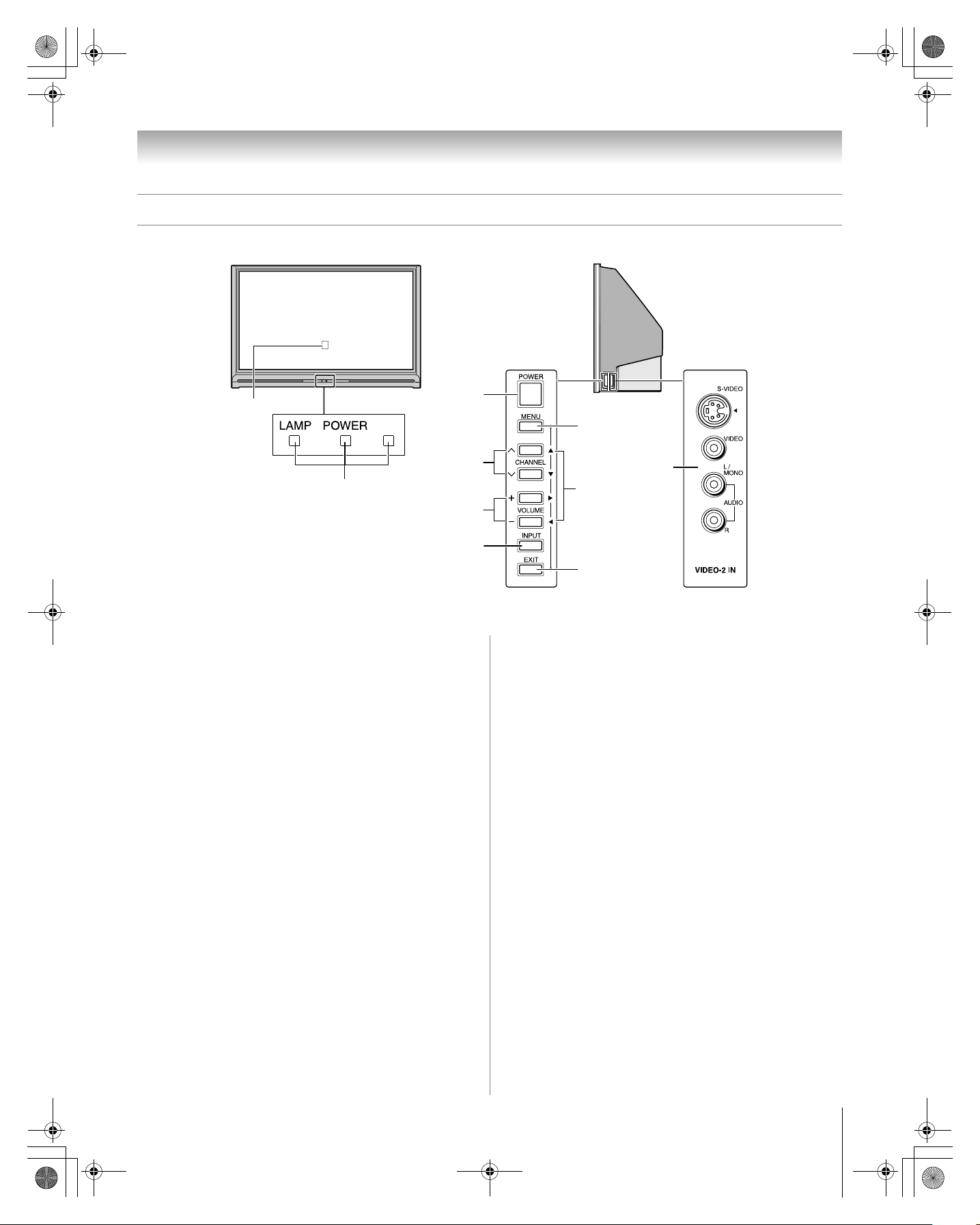
TV front and side panel controls and connections
Front of TV
1
2
1 Remote sensor (behind the screen) — Point the remote
control toward this area of the TV screen (- “Remote
control effective range” on page 22).
2 Blue, Yellow, and Green/Red
See “LED indications” on page 62 for additional
information.
3 POWER — Press to turn the TV on and off.
If the TV stops responding to the controls on the remote
control or TV control panel and you cannot turn off the
TV, press and hold the POWER button on the TV control
panel for 5 or more seconds to reset the TV.
4 CHANNEL Uu — When no menu is on-screen, these
buttons change the channel (programmed channels only;
- page 32).
5 VOLUME + – — These buttons adjust the volume level.
Right side of TV
3
7
4
10
8
5
6
9
Control panel
9 EXIT — Press to instantly close an on-screen menu.
10 VIDEO-2 IN — The side panel A/V connections are
referred to as “VIDEO 2” and include standard A/V
inputs plus an optional S-video input.
Note: Standard (composite) video and S-video cables
carry only video information; separate audio cables are
required for a complete connection.
Side panel
6 INPUT — Repeatedly press to change the source you are
viewing (ANT, VIDEO 1, VIDEO 2, ColorStream
HD1, ColorStream HD2, HDMI 1, HDMI 2, HDMI 3,
PC).
7 MENU (ENTER) — Press to access the menu system
(- pages 29–30). When a menu is on-screen, the MENU
button on the TV’s control panel functions as the ENTER
button.
8 ARROWS BbC c — When a menu is on-screen, these
buttons function as up/down/left/right menu navigation
buttons.
11
HM117 (E/F) Web 213:276
57HM117_EN.book Page 12 Friday, March 23, 2007 9:48 AM
Chapter 1: Introduction
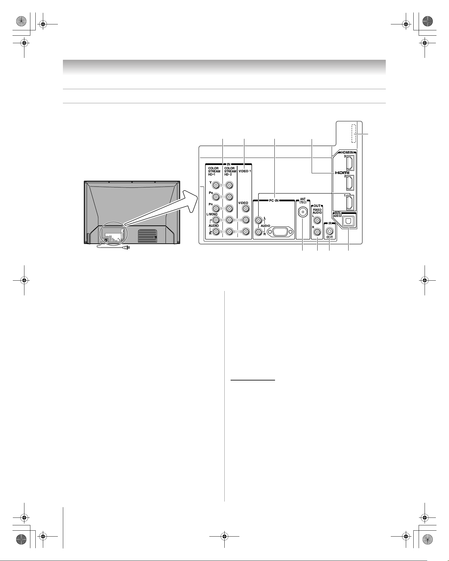
TV back panel connections
For an explanation of cable types and connections, see pages 13–21.
1 ColorStream® HD-1 and ColorStream® HD-2 —
Two sets of ColorStream
®
high-definition component
video inputs (with standard stereo audio inputs) for
connecting devices with component video output, such as
a Toshiba DVD player with ColorStream
Note: Component video cables carry only video
information; separate audio cables are required for a
complete connection.
®
.
2 VIDEO-1 IN — Standard (composite) video and standard
audio inputs for connecting devices with composite video
output.
3 PC IN — For use when connecting a personal computer.
PC audio input terminals are shared with HDMI-1 analog
audio input terminals, and their use can be configured in
the Audio Setup menu (- page 54).
4 HDMI
™
IN — High-Definition Multimedia Interface
input receives digital audio and uncompressed digital
video from an HDMI device or uncompressed digital
video from a DVI device. Also see item 3. HDMI
connection is necessary to receive 1080p signals.
5 ANT — Antenna input that supports analog (NTSC) and
digital (ATSC) off-air antenna signals and analog and
digital Cable TV (QAM) signals.
6 Fixed Audio OUT — Analog audio outputs for
connecting an audio amplifier.
12
3
4
5
7
6
8
7 IR OUT — For controlling infrared remote-controlled
devices through the TV. You can connect up to two
devices with an IR blaster cable, and then control the
devices using the TV’s IR pass-through features.
8 Digital Audio OUT — Optical audio output in Dolby
Digital or PCM (pulse-code modulation) format for
connecting an external Dolby Digital decoder, amplifier,
A/V receiver, or home theater system with optical audio
input.
9 Service port (behind the cover) — For service use
only. Used for updating the television’s firmware.
HDMI, the HDMI logo and High-Definition Multimedia Interface are
trademarks or registered trademarks of HDMI Licensing LLC.
Manufactured under license from Dolby Laboratories.
Dolby and the double-D symbol are registered trademarks of Dolby
Laboratories.
9
12
HM117 (E/F) Web 213:276
57HM117_EN.book Page 13 Friday, March 23, 2007 9:48 AM
Chapter 2: Connecting your TV
Overview of cable types
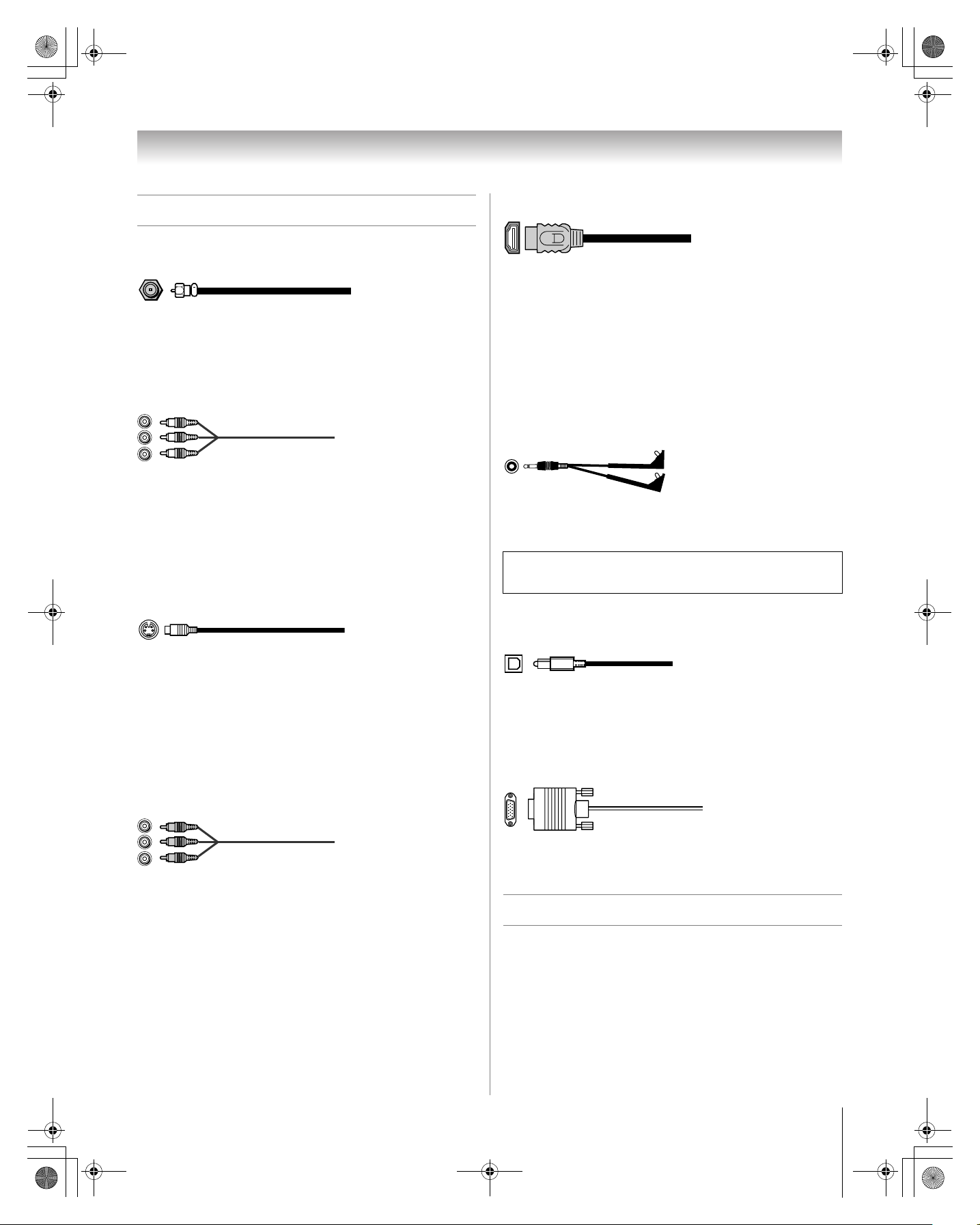
Coaxial (F-type) cable
Coaxial (F-type) cable is used for connecting your antenna,
cable TV service, and/or cable converter box to the ANT input
on your TV.
Standard A/V cables (red/white/yellow)
Standard A/V cables (composite video) usually come in sets of
three, and are for use with video devices with analog audio and
composite video output. These cables (and the related inputs
on your TV) are typically color-coded according to use: yellow
for video, red for stereo right audio, and white for stereo left
(or mono) audio.
S-video cable
HDMI™ cable
HDMI (High-Definition Multimedia Interface) cable is for use
with devices with an HDMI output. An HDMI cable delivers
digital audio and video in its native format. This cable carries
both video and audio information; therefore, separate audio
cables are not required for a complete HDMI device
connection (- page 19 and page 21).
Note: HDMI cable provides better picture performance than a
standard (composite) video or S-video cable.
Dual-wand IR blaster cable
Dual-wand IR blaster cable is for use with video devices with
IR (infrared) remote control. This cable can be used with the
TV’s IR pass-through feature (- page 17).
To obtain IR blaster cable:
Visit www.ceaccessories.toshiba.com.
S-video cable is for use with video devices with S-video
output. Separate audio cables are required for a complete
connection.
Note: An S-video cable provides better picture performance
than a composite video cable. If you connect an S-video cable,
be sure to disconnect the standard (composite) video cable or
the picture performance will be unacceptable.
Component video cables (red/green/blue)
Component video cables come in sets of three and are for use
with video devices with component video output.
(ColorStream
cables are typically color-coded red, green, and blue. Separate
audio cables are required for a complete connection.
Note: Component video cables provide better picture
performance than a standard (composite) video or S-video
cable.
®
is Toshiba’s brand of component video.) These
Optical audio cable
Optical audio cable is for connecting receivers with Dolby
Digital or PCM (pulse-code modulation) optical audio input to
the TV’s DIGITAL AUDIO OUT terminal (- page 20).
Analog RGB (15-pin) computer cable
Analog RGB (15-pin) computer cable is for connecting a PC to
the TV’s PC IN terminal (- page 21).
About the connection illustrations
You can connect different types and brands of devices to your
TV in several different configurations. The connection
illustrations in this manual are representative of typical device
connections only. The input/output terminals on your devices
may differ from those illustrated herein. For details on
connecting and using your specific devices, refer to each
device’s owner’s manual.
13
HM117 (E/F) Web 213:276
a
57HM117_EN.book Page 14 Friday, March 23, 2007 9:48 AM
Chapter 2: Connecting your TV
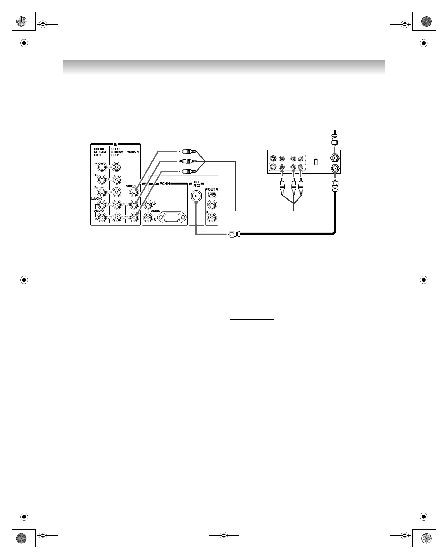
Connecting a VCR and antenna or Cable TV (no Cable box)
TV back panel
Stereo VCR
VIDEO AUDIO
From Cable TV or antenn
LR
IN
IN from ANT
CH 3
CH 4
OUT
OUT to TV
R
L
You will need:
• coaxial cables
• standard A/V cables
– For better picture performance, if your VCR has S-video,
use an S-video cable (plus the audio cables) to VIDEO 2
on the side panel (instead of to VIDEO 1). Do not connect
both types of video cable to VIDEO 2 at the same time or
the picture performance will be unacceptable.
– If you have a mono VCR, connect L/MONO on the TV to
your VCR’s audio out terminal using the white audio cable
only.
To view the antenna or Cable signal:
Select the ANT video input source on the TV.*
To view the VCR:
Turn ON the VCR. Select the VIDEO 1 video input source on
the TV.*
* To select the video input source, press INPUT on the remote control
(- page 23). To program the TV remote control to operate other
devices, see Chapter 3.
The unauthorized recording, use, distribution, or revision of
television programs, videotapes, DVDs, and other materials is
prohibited under the Copyright Laws of the United States and
other countries, and may subject you to civil and criminal
liability.
14
HM117 (E/F) Web 213:276
V
57HM117_EN.book Page 15 Friday, March 23, 2007 9:48 AM
Chapter 2: Connecting your TV
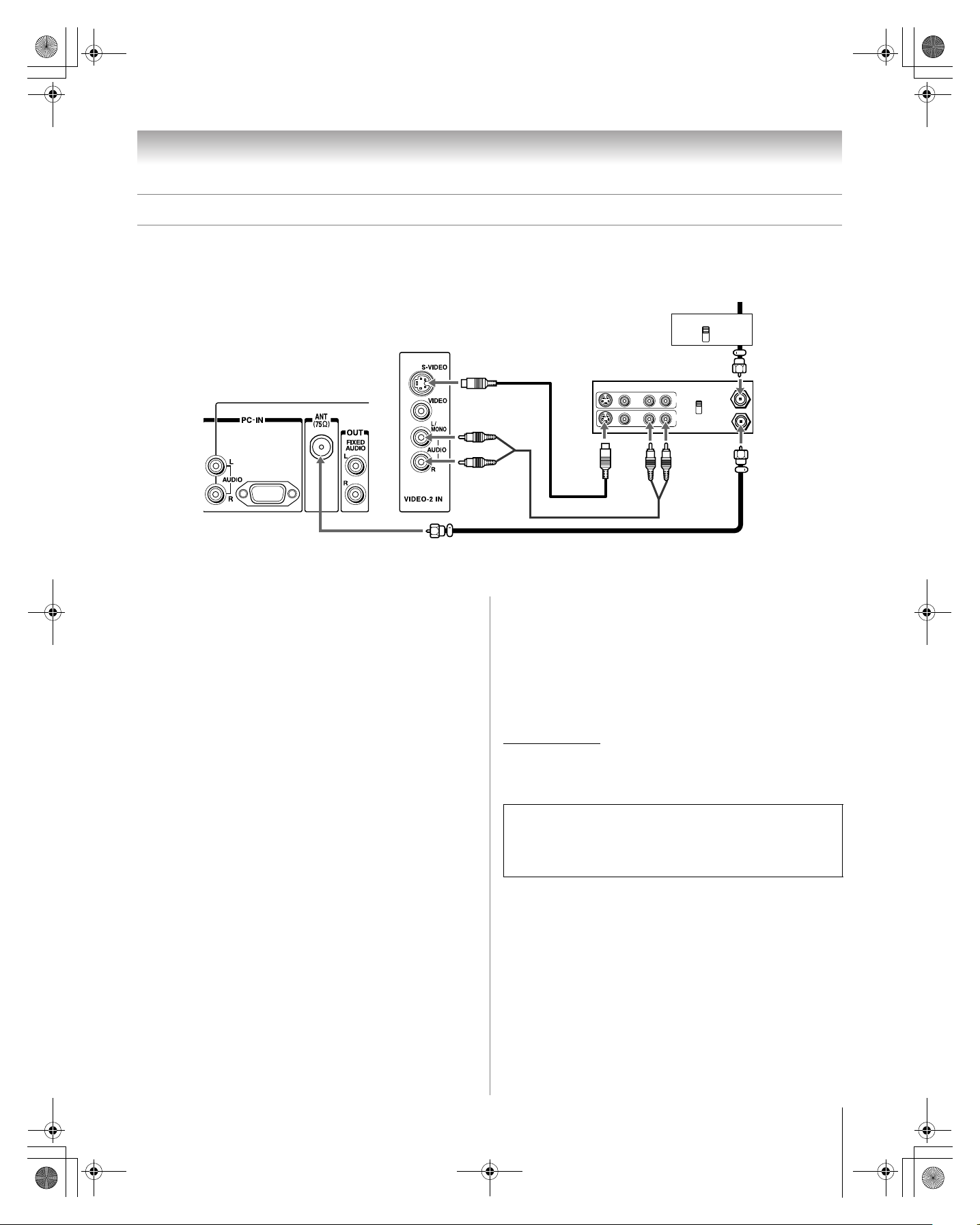
Connecting a VCR with S-video and a cable box
An S-video connection will provide better picture performance than a standard (composite) video cable.
TV right side panel
Cable box
IN
CH 3
CH 4
From Cable T
OUT
TV back panel
You will need:
• coaxial cables
• S-video cable
– Do not connect both types of video cable to VIDEO 2 at
the same time or the picture performance will be
unacceptable.
standard audio cables
•
– If you have a mono VCR, connect L/MONO on the TV to
your VCR’s audio out terminal using the white audio cable
only.
Note: When you use a Cable box, you may not be able to use
the remote control to program or access certain features on the
TV.
stereo VCR
VIDEO AUDIO
LR
IN
IN from ANT
CH 3
CH 4
OUT
OUT to TV
R
L
To view basic and premium Cable channels:
Turn OFF the VCR. Select the ANT video input source on the
TV.* Tune the TV to channel 3 or 4 (whichever channel the
Cable box output is set to). Use the Cable box controls to
change channels.
To view the VCR:
Turn ON the VCR. Select the VIDEO 2 video input source on
the TV.*
* To select the video input source, press INPUT on the remote control
(- page 23). To program the TV remote control to operate other
devices, see Chapter 3.
The unauthorized recording, use, distribution, or revision of
television programs, videotapes, DVDs, and other materials is
prohibited under the Copyright Laws of the United States and
other countries, and may subject you to civil and criminal
liability.
15
HM117 (E/F) Web 213:276
a
57HM117_EN.book Page 16 Friday, March 23, 2007 9:48 AM
Chapter 2: Connecting your TV
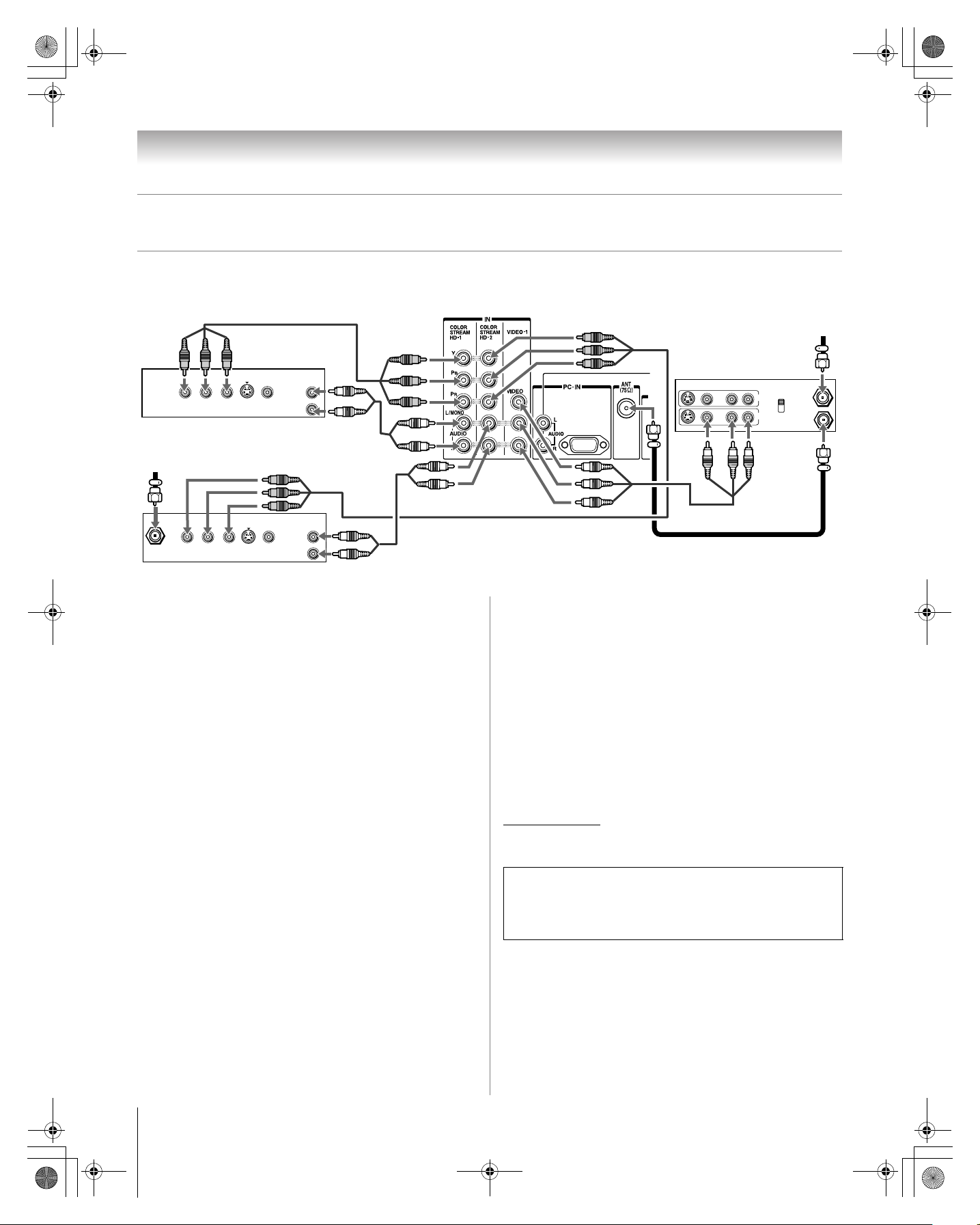
Connecting a DVD player with ColorStream® (component video), a VCR,
and a satellite receiver
Your TV has two sets of ColorStream® (component video) inputs.
TV back panel
From antenn
AUDIO
OUT
Y
P
B
COMPONENT VIDEO
P
R
VIDEO
S-VIDEO
OUT
OUT
L
R
DVD player with component video
From satellite dish
AUDIO
OUT
L
R
Satellite
IN
Y
P
B
COMPONENT VIDEO
P
R
VIDEO
S-VIDEO
OUT
OUT
Satellite receiver with component video
You will need:
• coaxial cables
• standard A/V cables
– For better picture performance, if your VCR has S-video,
use an S-video cable (plus the audio cables) to VIDEO 2
on the side panel (instead of to VIDEO 1). Do not connect
both types of video cable to VIDEO 2 at the same time or
the picture performance will be unacceptable.
– If you have a mono VCR, connect L/MONO on the TV to
your VCR’s audio out terminal using the white audio cable
only.
standard audio cables
•
• component video cables
– You can connect the component video cables (plus audio
cables) from the DVD player or satellite receiver to either
set of ColorStream terminals on the TV (HD-1 or HD-2).
The ColorStream HD-1 and HD-2 terminals can be used
with Progressive (480p, 720p) and Interlaced (480i, 1080i)
scan systems. A 1080i signal will provide the best picture
performance (1080p is not supported).
– If your DVD player or satellite receiver does not have
component video, connect a standard A/V cable to
VIDEO 2 on the side panel. If your DVD player has HDMI
video, see page 19.
To view antenna or Cable channels:
Select the ANT video input source on the TV.*
Stereo VCR
VIDEO AUDIO
LR
IN
IN from ANT
CH 3
CH 4
OUT
OUT to TV
R
L
To view satellite programs using the component video
connections:
Turn on the satellite receiver. Select the ColorStream HD-2
video input source on the TV.*
To view the VCR or view and record antenna
channels:
Turn ON the VCR. Tune the VCR to the channel you want to
watch. Select the VIDEO 1 video input source on the TV.*
To record a TV program while watching a DVD:
Turn ON the VCR. Tune the VCR to the channel to record.
Select the ColorStream HD-1 video input source on the TV*
to view the DVD.
* To select the video input source, press INPUT on the remote control
(- page 23). To program the TV remote control to operate other
devices, see Chapter 3.
The unauthorized recording, use, distribution, or revision of
television programs, videotapes, DVDs, and other materials is
prohibited under the Copyright Laws of the United States and
other countries, and may subject you to civil and criminal
liability.
To view the DVD player:
Turn ON the DVD player. Select the ColorStream HD-1
video input source on the TV.*
16
HM117 (E/F) Web 213:276
57HM117_EN.book Page 17 Friday, March 23, 2007 9:48 AM
Chapter 2: Connecting your TV
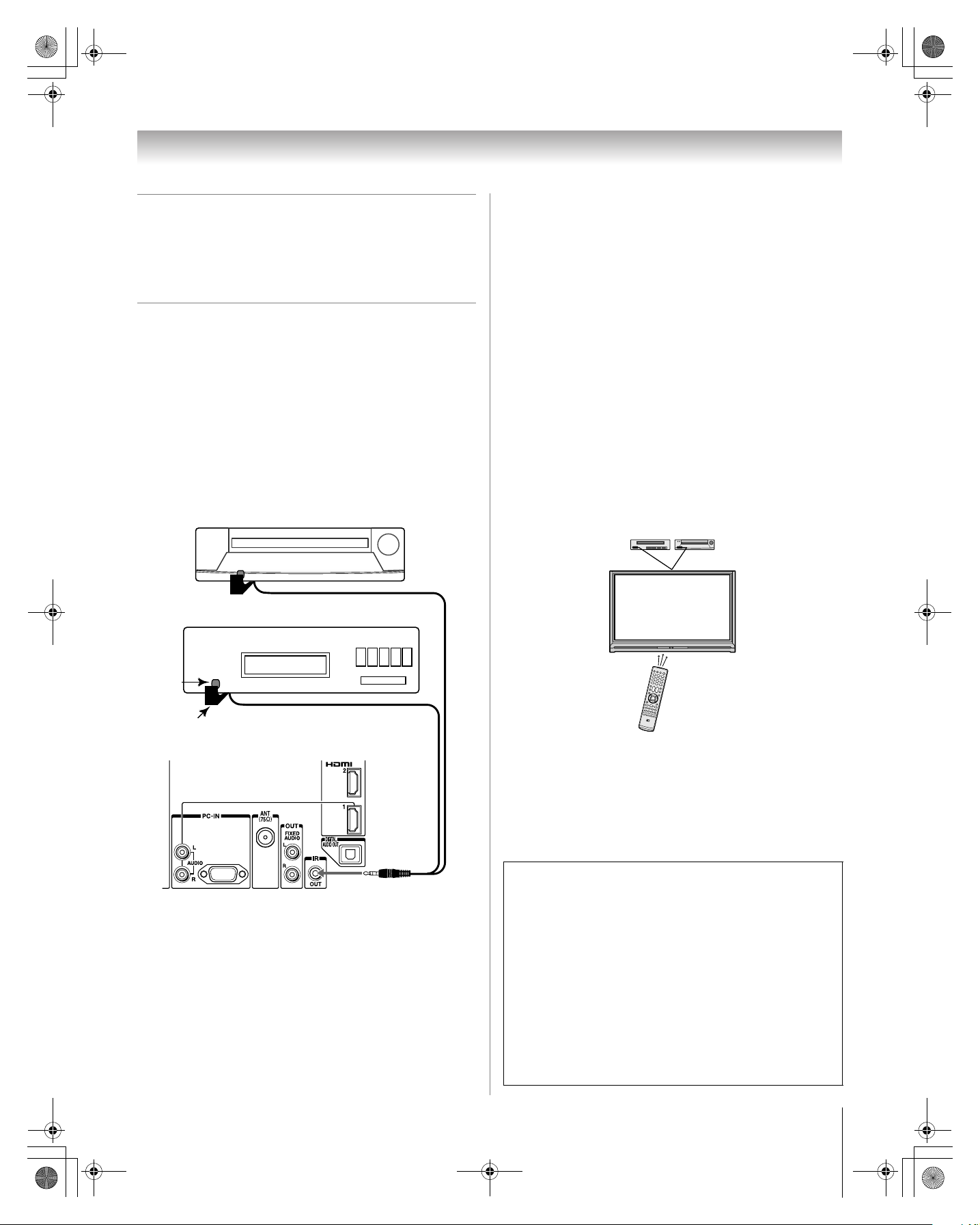
Connecting a device to the IR OUT
infrared terminal using the IR
blaster cable for IR pass-through
device control
You can use the TV’s IR OUT terminal (infrared passthrough) to remotely operate (through the TV) many infrared
remote-controlled devices (such as Toshiba infrared remotecontrolled VCRs or DVD players) enclosed within an
entertainment center or similar cabinet. Without the IR OUT
connection, the device typically would need to be visible to
operate it remotely.
You will need:
• dual-wand IR blaster cable (- page 13)
• other audio/video cables as required to connect the device(s)
to the TV (- pages 14–19)
Front of IR-controlled DVD player (for example)
To connect the IR blaster cable:
1 Locate the infrared sensor on the front of your device.
This sensor is marked on some devices.*
2 Align one of the IR blaster cable’s wands about 1 inch
away from the infrared sensor on the front of the device
and attach it using double-sided mounting tape. If you
have a second device, attach the second wand in a similar
manner. (See illustration.)
Note: If you do not have a second device, coil the second
wand with a rubber band and leave it behind the TV.
3 Plug the IR blaster cable’s plug into the TV’s IR OUT
terminal.
To control the device(s):
Point either the device’s remote control or the TV remote
control (that you previously programmed to operate the
device; - Chapter 3) toward the front of the TV and press the
button for the desired function. The signal passes from the
remote control through the TV to the device via the IR blaster
cable.
Front of IR-controlled audio device (for example)
Infrared
sensor
IR blaster cable wand
(approx.1 inch from device)
TV back panel
Note:
• If you use the device’s remote control to operate the device,
you also will need to use the TV’s remote control to operate
the TV.
• The IR pass-through feature does not support all
IR-controlled devices; satisfactory performance may not be
attainable with certain devices.
*If you cannot locate the device’s infrared sensor:
1 Turn OFF the device.
2 Starting at the lower left corner of the device, place the
end of the device’s remote control (with the infrared
emitter) so it touches the front of the device and press
POWER. (Do not use the TV’s remote control for this
step.)
3 If the device turns on, the point at which the remote
control touched the device is the location of the sensor.
4 If the device does not turn on, move the remote control
slightly to the right and press POWER again.
5 Repeat step 4 until you locate the device’s infrared
sensor.
17
HM117 (E/F) Web 213:276
57HM117_EN.book Page 18 Friday, March 23, 2007 9:48 AM
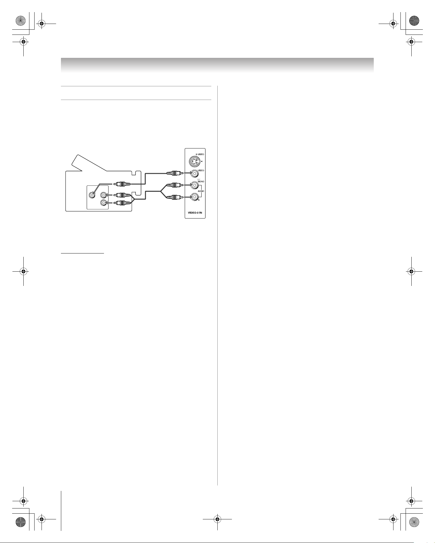
Connecting a camcorder
You will need:
• standard A/V cables
– For better picture performance, if your camcorder has
S-video, connect an S-video cable (plus the audio
cables).
Camcorder
VIDEO
AUDIO
OUT
L
R
Chapter 2: Connecting your TV
VIDEO 2 inputs on TV right side panel
To view the camcorder video:
Select the VIDEO 2 video input source on the TV.*
* To select the video input source, press INPUT on the remote control
(- page 23). To program the TV remote control to operate other
devices, see Chapter 3.
18
HM117 (E/F) Web 213:276
57HM117_EN.book Page 19 Friday, March 23, 2007 9:48 AM
Chapter 2: Connecting your TV
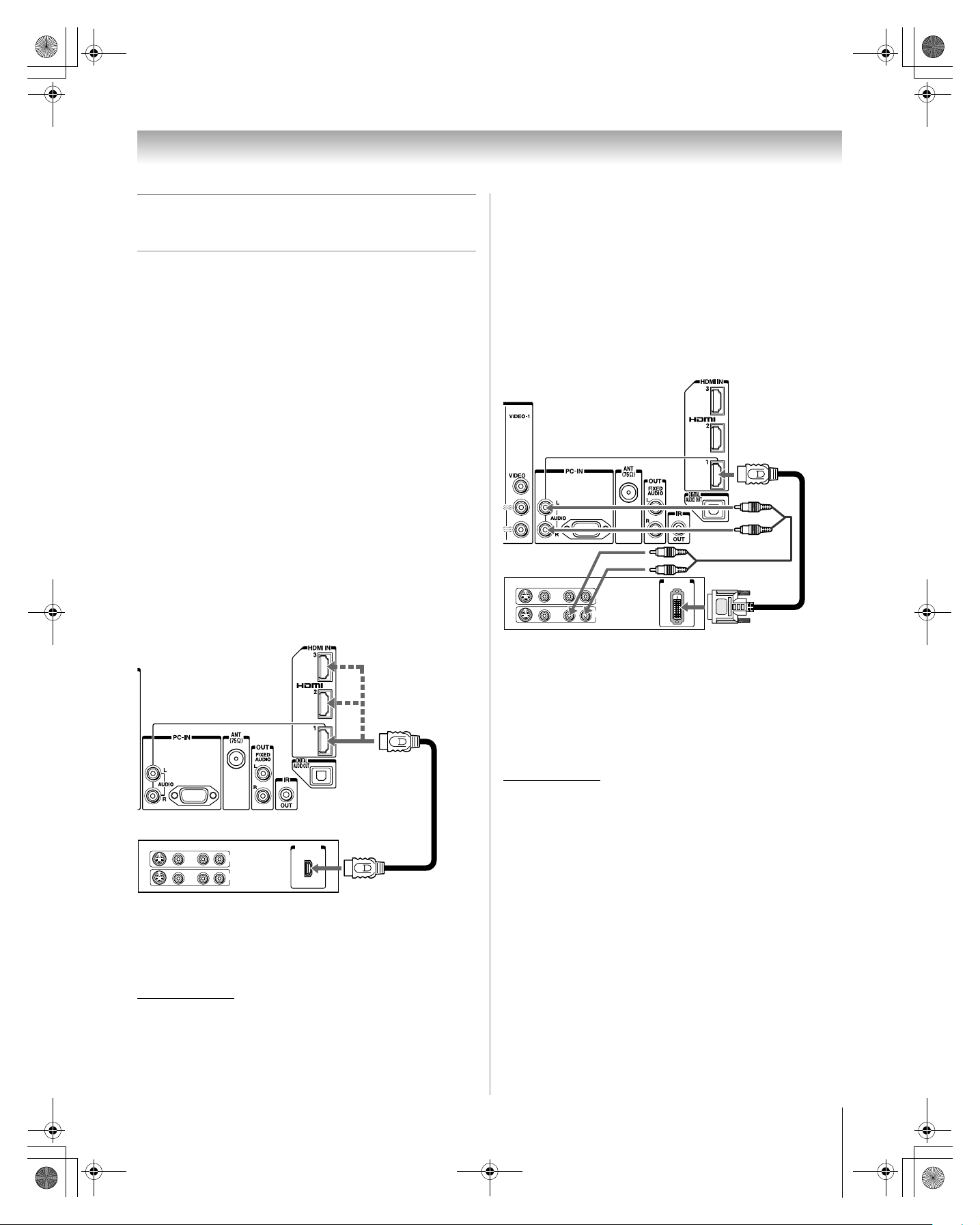
Connecting an HDMI™ or DVI device
to the HDMI input
The HDMI input on your TV receives digital audio and
uncompressed digital video from an HDMI source device, or
uncompressed digital video from a DVI (Digital Visual
Interface) source device.
This input is designed to accept HDCP (High-Bandwidth
Digital-Content Protection) program material in digital form
from EIA/CEA-861-861B–compliant
devices (such as a set-top box or DVD player with HDMI or
DVI output).
The HDMI input is designed for best performance with 1080p
signals but will also accept and display 480i, 480p, 720p, and
1080i signals.
Note: To connect a PC to the HDMI input, see page 21.
To connect an HDMI device, you will need:
• one HDMI cable (type A connector) per HDMI device
– For proper operation, it is recommended that you use an
HDMI cable with the HDMI Logo (HDMI
an HDMI cable shorter than 16.4 ft (5m) for 1080p input
signals.
– HDMI cable transfers both video and audio. Separate
analog audio cables are not required (see illustration).
™
– See “Setting the HDMI
audio mode” (- page 34).
[1]
consumer electronic
™
). You should use
To connect a DVI device, you will need:
• one HDMI-to-DVI adapter cable (HDMI type A connector)
per DVI device
– For proper operation, the length of an HDMI-to-DVI
adapter cable should not exceed 9.8 ft (3m). The
recommended length is 6.6 ft (2m).
one pair of standard analog audio cables per DVI device
•
– An HDMI-to-DVI adapter cable transfers video only.
Separate analog audio cables are required (see
illustration).
™
– See “Setting the HDMI
TV back panel
DVI device
VIDEO AUDIO
LR
IN
IN
OUT
R
L
audio mode” (- page 34).
DVI/ HDCP
OUT
TV back panel
HDMI device
VIDEO AUDIO
LR
L
IN
IN
OUT
R
HDMI OUT
To view the HDMI device video:
Select the HDMI 1, HDMI 2, or HDMI 3 video input source on
the TV.*
Note: If the audio output mode of the HDMI device is other
than the L-PCM mode, the TV speakers will not output sound.
* To select the video input source, press INPUT on the remote control
(- page 23). To program the TV remote control to operate other
devices, see Chapter 3.
Note: To ensure that the HDMI or DVI device is reset properly,
it is recommended that you follow these procedures:
• When turning on your electronic components, turn on the
TV first, and then the HDMI or DVI device.
• When turning off your electronic components, turn off the
HDMI or DVI device first, and then the TV.
[1] EIA/CEA-861-861B compliance covers the transmission of
uncompressed digital video with high-bandwidth digital content
protection, which is being standardized for reception of highdefinition video signals. Because this is an evolving technology, it
is possible that some devices may not operate properly with the TV.
HDMI, the HDMI logo and High-Definition Multimedia Interface are
trademarks or registered trademarks of HDMI Licensing LLC.
19
HM117 (E/F) Web 213:276
57HM117_EN.book Page 20 Friday, March 23, 2007 9:48 AM
Chapter 2: Connecting your TV
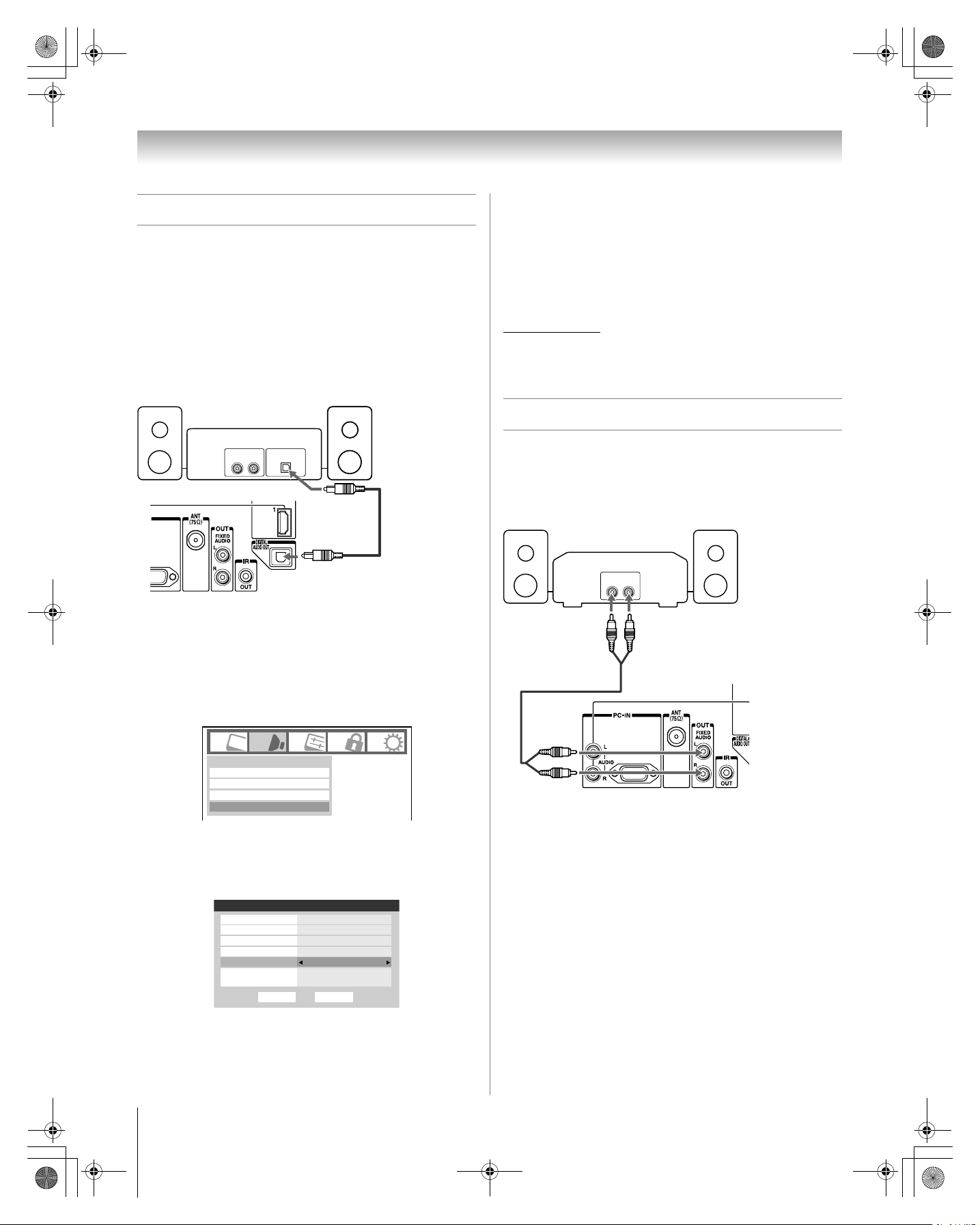
Connecting a digital audio system
The TV’s DIGITAL AUDIO OUT terminal outputs a Dolby®*
Digital g or 2-channel down-mixed PCM (pulse-code
modulation) signal for use with an external Dolby
decoder or other external audio system with optical audio
input.
You will need:
• optical audio cable (Use an optical audio cable that has the
larger “TosLink” connector and not the smaller “minioptical” connector.)
Dolby Digital decoder or
other digital audio system
Optical
Audio IN
LINE IN
LR
®
Digital
Note:
• Some audio systems may not be compatible with Dolby
Digital bitstream signals. Older audio systems that are not
compatible with standard optical out signals may not work
properly, creating a high noise level that may damage
speakers or headphones. THIS DAMAGE IS NOT COVERED
BY YOUR WARRANTY.
• The DIGITAL AUDIO OUT terminal may not output some
digital audio sources because of copy restrictions.
* Manufactured under license from Dolby Laboratories.
Dolby, and the double-D symbol are registered trademarks of Dolby
Laboratories.
Connecting an audio system
This connection allows you to use external speakers with an
external analog audio amplifier to adjust the sound level.
TV back panel
To control the audio:
1 Turn on the TV and the digital audio device.
2 Press Y on the TV’s remote control and open the Audio
menu.
3 Highlight Audio Setup and press T.
Audio
Digital Audio Selector
Audio Settings
Advanced Audio Settings
Audio Setup
4 In the Optical Output Format field, select either
Dolby Digital or PCM, depending on your device
(
- “Selecting the optical audio output format” on
page 48).
Audio Setup
PC Audio No
HDMI 1 Audio
MTS Stereo
Language
Optical Output Format
Dolby Digital
Dynamic Range Control
Reset
Auto
English
Dolby Digital
Compressed
Done
You will need:
• standard audio cables
Analog audio amplifier
LINE IN
LR
TV back panel
To control the audio:
1 Turn on the TV and the stereo amplifier.
2 Minimize the sound volume from the TV’s built-in
speakers and control the volume level using the
amplifier’s remote control.
20
HM117 (E/F) Web 213:276
57HM117_EN.book Page 21 Friday, March 23, 2007 9:48 AM
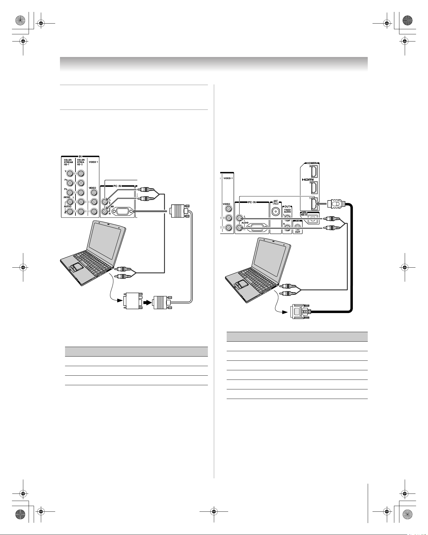
Connecting a personal computer
(PC)
Chapter 2: Connecting your TV
• Depending on the DVD’s title and the specifications of the
PC on which you are playing the DVD-Video, some scenes
may be skipped or you may not be able to pause during
multi-angle scenes.
To connect a PC to the PC IN terminal on the TV:
When connecting a PC to the PC IN terminal on the TV, use an
analog RGB (15-pin) computer cable and a PC audio cable.
TV back panel
PC audio
cable
Computer
PC audio
output
To connect a PC to the HDMI terminal on the TV:
When connecting a PC to the HDMI terminal on the TV, use
an HDMI-to DVI adapter cable and analog audio cables.
If connecting a PC with an HDMI terminal, use an HDMI cable
(type A connector). Separate analog cables are not necessary
(- page 19).
TV back panel
PC audio
cable
Computer
PC audio
output
Conversion adapter
(if necessary)
• To use a PC, set the monitor output resolution on the PC
before connecting it to the TV. The following signals can be
displayed:
Format Resolution V. Frequency
VGA 640 × 480 60Hz
SVGA 800 × 600 60Hz
XGA 1024 × 768 60Hz
Other formats or non-standard signals will not be displayed
correctly.
• To display the optimum picture, use the PC setting feature
(
- “Using the PC settings feature” on page 53).
Note:
• The PC audio input terminals on the TV are shared with the
HDMI-1 analog audio input terminals (- page 54).
• Some PC models cannot be connected to this TV.
• An adapter is not needed for computers with a compatible
mini D-sub15-pin terminal.
• The following signal formats can be displayed:
Format Resolution V. Frequency
VGA 640 × 480 59.94/60Hz
480i (60Hz) 720 × 480 59.94/60Hz
480p (60Hz) 720 × 480 59.94/60Hz
720p (60Hz) 1280 × 720 59.94/60Hz
1080i (60Hz) 1920 × 1080 59.94/60Hz
1080p (24/60Hz) 1920 × 1080 59.94/60Hz
Note: The edges of the images may be hidden.
21
HM117 (E/F) Web 213:276
57HM117_EN.book Page 22 Friday, March 23, 2007 9:48 AM
Chapter 3: Using the remote control
Preparing the remote control
for use
Your TV remote control can operate your TV and many other
devices such as cable converter boxes, satellite receivers,
VCRs, DVD players, and HTIBs (home theater in a box), even
if they are different brands.
If you have a Toshiba device:
Your TV remote control is preprogrammed to operate most
Toshiba devices (- page 26).
• Always remove batteries from the remote control if they are
dead or if the remote control is not to be used for an
extended period of time. This will prevent battery acid from
leaking into the battery compartment.
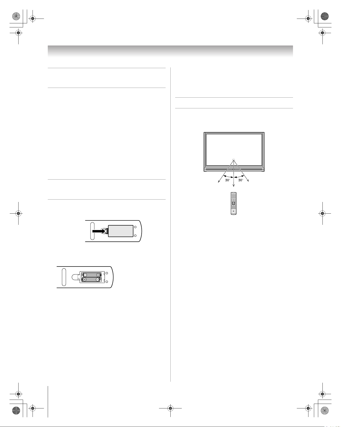
Remote control effective range
For optimum performance, aim the remote control directly at
the TV and make sure there is no obstruction between the
remote control and the TV.
If you have a non-Toshiba device or a Toshiba device
that the remote control is not preprogrammed to
operate:
You can program the TV remote control so it will operate the
other device (- pages 24–28).
Installing the remote control
batteries
1 Remove the battery cover from the back of the remote
control.
Squeeze tab
and lift cover.
2 Install two “AAA” size batteries, making sure to match
the + and – signs on the batteries to the signs on the battery
compartment.
Point remote control
toward remote sensor
on front of TV.
16.4 ft (5m)
3 Reinsert the battery cover in the remote control until the
tab snaps.
Caution: Never throw batteries into a fire.
Note:
• Be sure to use AAA size batteries.
• Dispose of batteries in a designated disposal area.
• Batteries should always be disposed of with the
environment in mind. Always dispose of batteries in
accordance with applicable laws and regulations.
• If the remote control does not operate correctly, or if the
operating range becomes reduced, replace batteries with
new ones.
• When necessary to replace batteries in the remote control,
always replace both batteries with new ones. Never mix
battery types or use new and used batteries in combination.
22
HM117 (E/F) Web 213:276
57HM117_EN.book Page 23 Friday, March 23, 2007 9:48 AM
Chapter 3: Using the remote control
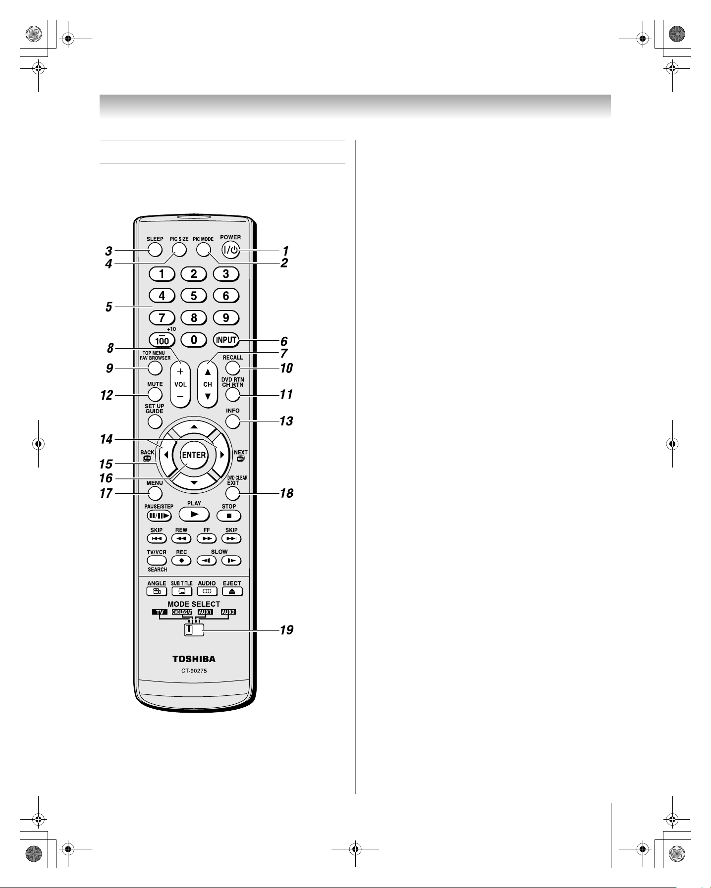
Learning about the remote control
The buttons used for operating the TV only are described here.
For a complete list of the remote control’s functions, see the
remote control functional key chart (- page 25).
1 POWER turns the TV on and off. Press p to turn on the
TV, The blue LED indicator on the TV front will be
illuminated. Press p again to turn off the TV.
Note: The Power-On Mode setting will affect the amount
of time it takes for the picture to appear when you turn on
the TV (- page 35).
2 PIC MODE selects the picture mode (- page 44).
3 SLEEP accesses the sleep timer (
- page 54).
4 PIC SIZE cycles through the picture sizes: Natural,
TheaterWide 1/2/3, Full, and 4:3 HD (
- page 41).
5 Channel Numbers (0–9, –/100) directly tune
channels. The = button is used to tune digital channels
(
- page 40) or to edit the Favorites List (- page 38).
6 INPUT selects the video input source (
- page 37).
7 CH Bb cycles through programmed channels when no
menu is on-screen (
- page 32).
8 VOL + – adjusts the volume level.
9 FAV BROWSER accesses the Favorites List in the
Channel Brower
™
(- page 38).
10 RECALL displays TV status information (- page 55).
11 CH RTN returns to the last viewed channel or source
(- page 40).
12 MUTE reduces or turns off the sound (- page 46).
13 INFO displays TV status information as well as program
details, when available (- page 55).
14 3C / #c While watching TV, these buttons open the
Channel Browser
™
and tune to the previous/next channel
in the channel history (- page 39). (Also see “Arrow
buttons.”)
15 Arrow buttons (BbC c) When a menu is on-screen,
these buttons select or adjust programming menus. (Also
see 3C/ #c.)
16 ENTER activates highlighted items in the main menu
system.
17 MENU accesses the main TV menu system (
- pages 29
and 30).
18 EXIT closes on-screen menus.
19 MODE SELECT switch switches between TV,
CABLE/SAT, AUX 1, and AUX 2 modes (
- page 24).
Set to “TV” to control the TV.
Note: The error message “Not Available” may appear if you
press a key for a function that is not available.
23
HM117 (E/F) Web 213:276
 Loading...