


Toro 74901, 74901CP, 74902TE, 74903, 74903CP Service Manual
...HY13-1521-M2/US
Parker Product
Effective: January, 2010
UHT
Product Series
Service Procedure

HY13-1521-M2/US |
Service Manual |
|
General Information |
Series HB Hydrostatic Transmission |
|
|
|
|
WARNING
FAILURE OR IMPROPER SELECTION OR IMPROPER USE OF THE PRODUCTS AND/OR SYSTEMS DESCRIBED HEREIN OR RELATED ITEMS CAN CAUSE DEATH, PERSONAL INJURY AND PROPERTY DAMAGE.
This document and other information from Parker Hannifin Corporation, its subsidiaries and authorized distributors provide product and/or system options for further investigation by users having technical expertise. It is important that you analyze all aspects of your application and review the information concerning the product or system in the current product catalog. Due to the variety of operating conditions and applications for these products or systems, the user, through its own analysis and testing, is solely responsible for making the final selection of the products and systems and assuring that all performance, safety and warning requirements of the application are met.
The products described herein, including without limitation, product features, specifications, designs, availability and pricing, are subject to change by Parker Hannifin Corporation and its subsidiaries at any time without notice.
© Copyright 2009, Parker Hannifin Corporation, All Rights Reserved
2
Parker Hannifin Corporation
Hydraulic Pump/Motor Division
Greeneville, Tennessee USA

HY13-1521-M2/US |
Service Manual |
||
General Information |
Series HB Hydrostatic Transmission |
||
|
|
|
|
Section 1 |
General Information |
|
|
|
Definitions/Disclaimer |
4 |
|
|
Introduction/Design Features |
5 |
|
|
Troubleshooting Guide |
6 |
|
|
Troubleshooting Checklist |
7 |
|
|
Tools & Materials Required for Servicing |
8 |
|
|
Flow Test Instructions |
9-10 |
|
|
Exploded Views |
11-20 |
|
Section 2 Reseal & Repair |
|
||
|
Disassembly & Assembly - Fan Option |
21 |
|
|
Disassembly |
22-29 |
|
|
Assembly |
30-38 |
|
Section 3 |
Maintenance |
|
|
|
System Maintenance Tips |
39 |
|
|
Hydraulic Fluids |
39 |
|
|
Filtration |
39 |
|
|
Oil Temperature |
39 |
|
3
Parker Hannifin Corporation
Hydraulic Pump/Motor Division
Greeneville, Tennessee USA
HY13-1521-M2/US |
|
Service Manual |
|
General Information |
Series HB Hydrostatic Transmission |
||
|
|
|
|
|
WARNING |
A warning describes hazards or unsafe practices which could result in severe |
|
personal injury or death.
CAUTION A caution describes hazards or unsafe practices which could result in personal injury or product or property damage.
NOTE A note gives key information to make following a procedure easier or quicker.
Disclaimer
This Service Manual has been prepared by Parker Hannifin Corporation for reference and use by mechanics who have been trained to repair and service hydraulic pumps on commercial and non-commercial equipment applications. Parker Hannifin Corporation has exercised reasonable care and diligence to present accurate, clear and complete information and instructions regarding the techniques and tools required for maintaining, repairing and servicing the Parker UHT Series. Since this is a general Service Manual, the photographs and illustrations may not look exactly like the UHT being serviced. The procedures, therefore, must be carefully read and understood before servicing.
If inspection or testing reveals evidence of abnormal wear or damage to the UHT or if you encounter circumstances not covered in the Manual, STOP - CONSULT THE EQUIPMENT MANUFACTURER’S SERVICE MANUAL AND WARRANTY. DO NOT TRY TO REPAIR OR SERVICE A UHT Series WHICH HAS BEEN DAMAGED OR INCLUDES ANY PART THAT SHOWS EXCESSIVE WEAR UNLESS THE DAMAGED AND WORN PARTS ARE REPLACED WITH ORIGINAL PARKER REPLACEMENT AND SERVICE PARTS AND THE UNIT IS RESTORED TO PARKER SPECIFICATIONS FOR THE UHT Series.
It is the responsibility of the mechanic performing the maintenance, repairs or service on a particular UHT Series to (a) inspect the unit for abnormal wear and damage, (b) choose a repair procedure which will not endanger his/her safety, the safety of others, the equipment or the safe operation of the UHT Series, and (c) fully inspect and test the UHT Series and the hydraulic system to ensure that the repair or service of the UHT Series has been properly performed and that the UHT Series and hydraulic system will function properly.
Conversions
Inches |
Mm |
Inches |
mm |
.020 |
.511 |
1.060 |
26.92 |
.021 |
.531 |
1.295 |
32.89 |
.029 |
.741 |
1.297 |
32.94 |
.030 |
.760 |
1.396 |
35.46 |
.111 |
2.81 |
1.398 |
35.51 |
.119 |
3.02 |
1.620 |
41.15 |
.152 |
3.86 |
1.622 |
41.20 |
.160 |
4.06 |
1.983 |
50.37 |
.296 |
7.52 |
1.985 |
50.42 |
.304 |
7.72 |
2.120 |
53.85 |
.460 |
11.68 |
2.122 |
53.90 |
.470 |
11.94 |
2.233 |
56.72 |
.500 |
12.70 |
2.235 |
56.77 |
.585 |
14.86 |
2.483 |
63.07 |
.595 |
15.11 |
2.485 |
63.12 |
.660 |
16.76 |
2.500 |
63.5 |
.675 |
17.15 |
2.88 |
73.2 |
1.058 |
26.87 |
|
|
4
Parker Hannifin Corporation
Hydraulic Pump/Motor Division
Greeneville, Tennessee USA

HY13-1521-M2/US |
Service Manual |
|
General Information |
Series HB Hydrostatic Transmission |
|
|
|
|
Introduction
The three-column format used in this Service Manual will help make it easy for you to service a UHT. Column 1 illustrates the procedure with photographs, Column 2 gives a brief key for each step, and Column 3 explains in detail the procedure you should follow. Pay special attention to the notes, cautions, and warnings.
This manual contains troubleshooting information and checklists. With them you can diagnose a hydraulic system problem without removing the entire assembly the checklists will help you to determine where the problem may be.
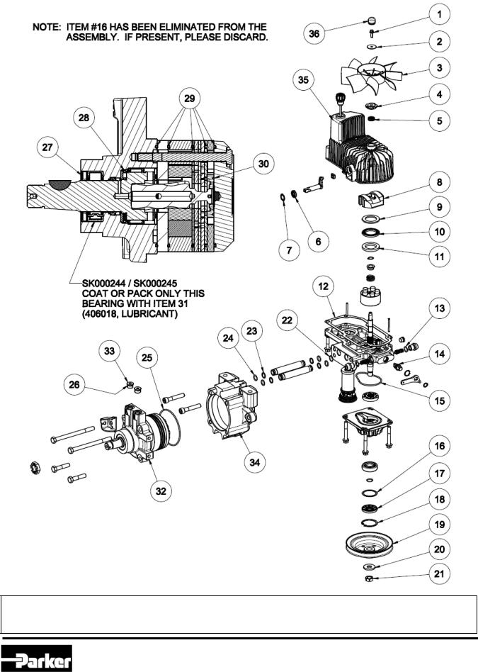
Item numbers on the exploded view correspond with item numbers used throughout the Service Manual.
As you gain experience in servicing UHT Series, you may find that some information in this Service Manual could be clearer and more complete. If so, let us know about it. Don’t try to second-guess the Service Manual; if problems occur that you cannot solve, please contact your local OEM approved distributor. Servicing UHT Series should be safe and productive.
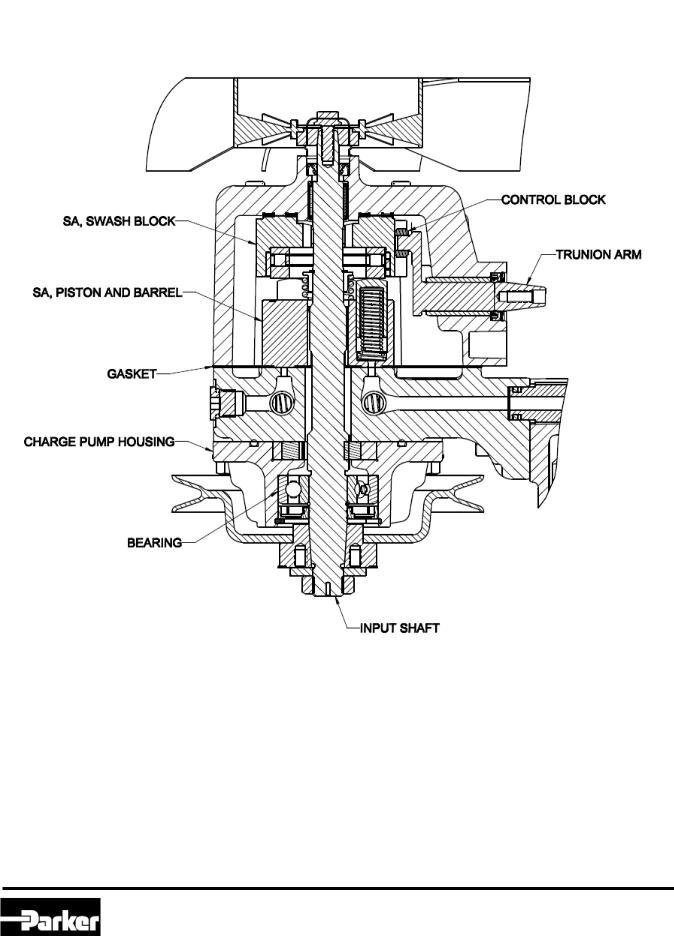
DESIGN FEATURES
UHT
Large area cooling fins result in a cooler running system
Top housing and charge pump cover are sturdy, lightweight aluminum, excellent at dispersing heat, resulting in an overall cooler system
Forged trunnion shaft increases shaft strength and lengthens pump life
Double caged thrust bearing improve lubrication and vibration absorption, thus lengthening life of pump
Torqmotor
Roller vane to reduce friction and internal leakage and to maintain efficiency
A patented orbiting commutator system for less wear and longer life
A unique high-pressure shaft seal that eliminates the need for case drain
Manifold designed to improve operating efficiency
Roller vane and sealed commutation assure high volumetric efficiency and smooth low speed operation
5
Parker Hannifin Corporation
Hydraulic Pump/Motor Division
Greeneville, Tennessee USA

HY13-1521-M2/US |
Service Manual |
|
General Information |
Series HB Hydrostatic Transmission |
|
|
|
|
Troubleshooting Guide
NOTE
Before troubleshooting any system problem, check service literature published by the equipment and/or component manufacturers. Follow their instructions, if given, for checking any component other than the transmission.
Preparation
Make your troubleshooting easier by preparing as follows:
•work in a clean, well-lighted place
•have proper tools and materials nearby
•have an air pressure source.
WARNING
Since solvents are flammable, be extremely careful when using any solvent. Even a small explosion could cause injury or death.
WARNING
Wear eye protection and be sure to comply with OSHA and other maximum air pressure requirements.
Preliminary Checks
Hydraulic systems are often trouble-free. Hence, the problem an operator complains of could be caused by something other than the hydraulic components.
Thus, once you have determined that a problem exists, start with the easy-to-check items, such as:
•Parts damaged from impact that were not properly repaired, or that should have been replaced
•Improper replacement parts used in previous servicing
•Mechanical linkage problems such as binding, broken or loose parts, or slipping belts
Hydraulic Components
If you think the problem is caused by a hydraulic component, start by checking the easy-to-reach items.
Check all belts for cracks, hardening or other signs of wear. Check all pulleys, fans and bolts to make sure they are tightened to specified torque value. Look for leaks, especially at coupling shaft, plugs and fittings.
Next, go to the reservoir and filters. Check fluid level and look for air bubbles. Check external filter(s). A filter with a maximum of 25 - 30 micron filtration is recommended for the UHT system.
Visually check other components to see if they are loosely mounted, show signs of leaks, or other damage or wear.
Excessive heat in a hydraulic system can create problems that can easily be overlooked. Every system has its limitation for the maximum amount of temperature. After the temperature is attained and passed, the following can occur:
•oil seal leaks
•pump loss of efficiency (resulting in lower transmission speeds)
•pump failure
•belts become hard and brittle
•pulley lose
A normal temperature range means an efficient hydraulic system. Consult the manuals published by equipment and/or component manufacturers for maximum allowable temperatures and hydraulic tests that may be necessary to run on the performance of the hydraulic components. The UHT is not recommended for hydraulic systems with maximum temperatures above 280o F (137o C).
6
Parker Hannifin Corporation
Hydraulic Pump/Motor Division
Greeneville, Tennessee USA

HY13-1521-M2/US |
Service Manual |
|
General Information |
Series HB Hydrostatic Transmission |
|
|
|
|
Troubleshooting Checklist
Trouble |
Cause |
Remedy |
|
||
Oil Leakage |
1. |
Fitting loose, worn or |
Check & replace damaged fittings or |
|
|
|
|
damaged. |
“O” rings. Torque to manufacturers |
|
|
|
|
|
|
specifications. |
|
|
|
2. |
Oil seals deteriorated |
Replace oil seals by disassembling |
|
|
|
by excess heat. |
unit. |
|
|
Operates Hot |
1. Debris buildup |
Remove debris |
|
||
|
|
|
|
Replace fan |
|
|
|
2. |
Cooling fan damaged |
||
|
|
|
|
Fill or change filter |
|
|
|
3. |
Oil level low or |
||
|
|
contaminated |
Reduce vehicle load |
|
|
|
|
4. |
Excessive loading |
|
|
|
|
|
|
Run vehicle slowly forward and then |
|
|
|
5. |
Air trapped in system |
||
|
|
|
|
reverse several times |
|
|
|
6. |
Mowing conditions |
Heavy grass or embankments |
|
|
|
|
Adjust setting |
|
|
No/Low Power |
1. Engine speed low |
||||
|
|
|
|
Fill or change filter |
|
|
|
2. |
Oil level low or |
||
|
|
contaminated |
Turn to closed (horizontal) position |
|
|
|
|
3. |
Bypass turned |
|
|
|
|
|
|
Reduce vehicle load |
|
|
|
4. |
Excessive loading |
||
|
|
|
|
Purge per instructions |
|
|
|
5. |
Air trapped in system |
||
|
|
|
|
Disassemble and inspect |
|
|
|
6. |
Suspect internal |
||
|
|
|
|
Tighten to specifications |
|
|
|
7. |
Pulley or belt loose |
||
|
|
|
Adjust input speed above 1800 rpm |
|
|
|
|
|
|
||
Noisy Unit |
1. Excessive speed input |
||||
|
|
|
|
and below 3600 rpm |
|
|
|
2. |
Oil level low or |
Fill or change filter |
|
|
|
contaminated |
Reduce vehicle load |
|
|
|
|
3. |
Excessive loading |
|
|
|
|
|
|
Run vehicle slowly forward and then |
|
|
|
4. |
Air trapped in system |
||
|
|
|
|
reverse several times |
|
|
|
5. |
Bypass valve open |
Turn to closed (horizontal) position |
|
|
|
|
|
|
|
|
|
|
|
|
|
|
|
|
|
|
|
7
Parker Hannifin Corporation
Hydraulic Pump/Motor Division
Greeneville, Tennessee USA
HY13-1521-M2/US |
Service Manual |
|
General Information |
Series HB Hydrostatic Transmission |
|
|
|
|
Tools and Materials Required for Servicing
•Clean, petroleum-based solvent
•Emery paper
•Vise with soft jaws
•Air-pressure source
•Arbor press
•Flat screwdriver
•Grease pencil or paint pen
•Wheel puller
•1/4" torque wrench : 155-190 in-lbs, 282-342 in-lbs, 90-110 in-lbs, 160-200 in-lbs
•Sockets: 3/8" drive ratchet, 5/16" hex, 1/4” hex, 3/8” hex, 10mm, 14mm, 16mm
•Allen wrenches: 5mm, 6mm, 1/4" and 3/8”
•Combination wrenches:
•Locking pliers
•Internal & external snap ring pliers
•Loctite ™ 242
•Grease – Mobil Mobilith SHC PM 460
•Oil – Recommended OEM Type Oil
•Four inch adjustable spanner wrench (Armstrong 34-157) or three inch fixed spanner (Armstrong 34124)
CAUTION
Mixing greases that have different bases can be detrimental to bearing and seal life.
8
Parker Hannifin Corporation
Hydraulic Pump/Motor Division
Greeneville, Tennessee USA

HY13-1521-M2/US |
Service Manual |
|
General Information |
Series HB Hydrostatic Transmission |
|
|
|
|
UHT Flow Test Kit Instructions
SK000251
Parts List
Item |
Qty |
Part Number |
Description |
Torque |
|
|
|
|
|
1 |
1 |
414002 |
SAE Swivel Fitting |
525 in lbs. |
|
|
|
|
|
2 |
1 |
411102 |
Needle Valve |
525 in lbs. |
|
|
|
|
|
3 |
2 |
414003 |
Gauge Fitting “T” |
165-525 in lbs. |
|
|
|
|
|
4 |
2 |
411103 |
3000 PSI Pressure Gauge |
165 in lbs. |
|
|
|
|
|
5 |
2 |
411104 |
Hose Assembly |
525 in lbs. |
|
|
|
|
|
6 |
2 |
414005 |
Reducer Fitting |
525-950 in lbs. |
|
|
|
|
|
7 |
1 |
411105 |
20 GPM Flow Meter |
525 in lbs. |
|
|
|
|
|
8 |
1 |
409350 |
Diagnostic Plug |
525 in lbs. |
|
|
|
|
|
9 |
1 |
SAE-J514-8-8-070120CF |
Straight Thread Fitting |
525 in lbs. |
|
|
|
|
|
- |
1 |
SK000251 |
Service Bulletin |
N/A |
|
|
|
|
|
Overview:
The Flow Test Kit allows the dealer to easily determine if UHT pump is faulty by isolating the pump section from the wheel motor. The following information describes how to test the pump by installing the Flow Test Kit and simulating a wheel motor load.
Procedure:
1.Raise the drive tires off the ground and block the remaining tires to prevent movement of the vehicle during testing.
2.Remove wheel from the hub to gain access to motor.
3.Ensure the pump bypass lever is in the “Closed” position (horizontal).
4.Isolate the pump from the wheel motor by removing the two plugs from the top of the wheel motor assembly and installing the Flow Test Kit. Install the Diagnostic Plug in port “A”, and the Straight Thread Fitting in port “B”. Take precautions to ensure no debris gets into the wheel motor system ports.
There is no need to determine the direction of flow with the Parker flow tester. The flow meter may be connected in either direction into the high pressure system lines.
9
 WARNINGS
Portions of this procedure require testing while the vehicle is operated in an elevated position.
Ensure vehicle is properly secured to prevent injury to the service technician or bystanders.
Do not attempt any adjustments with the engine running. When working around vehicle linkages, use extreme caution.
High temperatures can be generated.
Follow all safety procedures in the vehicle owner’s manual.
Parker Hannifin Corporation
Hydraulic Pump/Motor Division
Greeneville, Tennessee USA

HY13-1521-M2/US |
Service Manual |
|
General Information |
Series HB Hydrostatic Transmission |
|
|
|
|
CAUTION: All fittings and hoses must be securely attached. The test is accomplished using the vehicle’s high pressure system lines. Failure to secure connections could result in bodily injury.
5.Completely open the restriction valve.
6.Start the engine and, if required, engage the drive pulley.
7.Slowly bring engine up to maximum operating speed.
8.Move the vehicle’s directional control lever on the pump being tested all the way into the forward position. Lock the control arm into position to prevent false readings.
9.Continue to operate without any load to allow the system oil temperature to rise.
NOTE: Raising the temperature of the oil will make a difference in your readings. To complete the test accurately, the oil temperature should fall between 110˚ and 140˚ F.
10.Tighten the restriction valve until the difference between the pressure gauge readings is 300 psi (21 bar). Record the flow reading from the bi-directional flow meter.
11.Tighten the restriction valve until the difference between the pressure gauge readings is 1000 psi (69 bar) and record the flow reading again.
12.The maximum allowable flow rate change is shown below. If the difference exceeds this level, the pump is unacceptable.
13.When testing is complete, re-install the motor port plugs. Torque to 35 to 50 ft-lb.
Series |
Displacement |
Max. Allowable Flow Rate |
|
cc/rev |
|||
Change* (gpm) |
|||
|
(nominal) |
||
|
|
||
UHT |
12 to 16 |
1.0 |
* Max. Allowable Flow Rate Change is equal to the flow rate at 300 psi minus the flow rate at 1000 psi.
10
Parker Hannifin Corporation
Hydraulic Pump/Motor Division
Greeneville, Tennessee USA
HY13-1521-M2/US |
Service Manual |
|
General Information |
Series HB Hydrostatic Transmission |
|
|
|
|
EXAMPLE: |
|
First Reading |
300 psi (21 bar) 5 gpm (19 l/min) |
Second Reading |
1000 psi (69 bar) - 3 gpm (11 l/min) |
Difference |
2 gpm (8 l/min) |
By subtracting the second reading from the first, a defective pump can be identified. In the example above, 2 gpm indicates a defective pump.
11
Parker Hannifin Corporation
Hydraulic Pump/Motor Division
Greeneville, Tennessee USA

HY13-1521-M2/US |
Service Manual |
|
General Information |
Series HB Hydrostatic Transmission |
|
|
|
|
12
Parker Hannifin Corporation
Hydraulic Pump/Motor Division
Greeneville, Tennessee USA
HY13-1521-M2/US |
Service Manual |
|
General Information |
Series HB Hydrostatic Transmission |
|
|
|
|
13
Parker Hannifin Corporation
Hydraulic Pump/Motor Division
Greeneville, Tennessee USA
HY13-1521-M2/US |
Service Manual |
|
General Information |
Series HB Hydrostatic Transmission |
|
|
|
|
Note: When servicing UHT assemblies with a serial number code of 09256 or earlier, item 29 is not required.
When servicing UHT assemblies with a serial number code of 09257 or after, item 25 is not required. Though item 22 is provided in the seal kit, it can be discarded if the endblock does not include a machined seal groove.
14
Parker Hannifin Corporation
Hydraulic Pump/Motor Division
Greeneville, Tennessee USA
 Loading...