

Page 1
BUILDING and FLYING the
Page 2

INTRODUCTION
It has been suggested for several years that a control line stunter would
make a fine radio controlled model The fairly recent advent of miniaturized
radio control systems has permitted testing this possibility The
Nobler
is ideal for
this conversion because of its airfoil planform and structure
The control line
designed by
George
The radio control version of the
Nobler
is the winningest of all control line stunters It was
Aldrich and has been a
Nobler
Top
Flite
kit
for many
has been the project of Ed Sweeney
years
with considerable technical assistance by Fred Marks Many models were built
in developing the Top Flite
R/C Nobler
kit We think it will follow the
winning ways of its line bound ancestor It opens up a new dimension in precision
RC acrobatics
The airplane has a great airfoil with excellent stability, lift, smooth response,
and gentle stall characteristics Thrust and drag forces are near both center of
pressure and gravity It is a relatively symmetrical aircraft — high thrust
line
high
stabilizer,
air foil This symmetry gives the plane its true neutral stability
deep fuselage
cross
section, and mid wing with symmetrical
It
will hold any
reasonable flying attitude almost indefinitely
BEFORE YOU START—READ THIS!
These
instructions
have
been
carefully
developed after
building
several
prototype models We urge you, in your own interest, not to ignore them Our
aim is to insure that the model goes together in a reasonably quick time
and
without annoying snags
Regardless
of previous modeling experience
follow the directions carefully,
checking them off as you go
Notice the instructions often call for some items to be started before others
are complete This is to allow time for important glue joints to dry properly,
yet not hold up building progress Also in order to help modelers of less experience,
we have tended to the easier jobs first, leaving those requiring more care until
later as skill increases.
Do
not
seperate
parts from die cut sheets
until
you
need
them
This
will
save loss or breakage of some of the small or delicate pieces
We are often asked by less-experienced modelers which glues are best
for model construction The answer to this depends upon the particular job
However this is our normal recommendation For all hardwood to hardwood
or hardwood to balsa joints use white wood glue Titebond is especially good,
as
it
drys
faster than other
white
glues and
is
very
strong
For
balsa
to
balsa
joints regular balsa wood cements are ample for the job although white glue
can be used here too Whichever type you use, remember that excess glue is no
substitute for a well fitting joint Use a minimum of glue at all times, and wipe off
excess glue that squeezes out of joints before it sets hard when set it is difficult
to remove, but if not removed it will spoil the covering job
For joints involving flexible items like foam rubber
R/C equipment packing,
contact cement is the only suitable adhesive this should not be used in construction however because it is not sufficiently strong and is very hard to sand
down
properly
One final word to newcomers to the hobby or modelers of limited ex-
perience Join a club! (You can write to the Academy of Model Aeronautics,
1239 Vermont Avenue N W Washington D C 20005, for the address of
your nearest Club Secretary ) Here you will find indispensable guidance and help
from experienced and friendly fellow modelers should you encounter any small
problem in building or flying this model We at Top Flite will do our best to insure
your success, but it is fair to say that nothing can replace personal help or demon-
stration from a good modeler
1
Page 3
SUB-ASSEMBLIES
To speed building, by cutting down "waiting time," it is recommended that
certain components
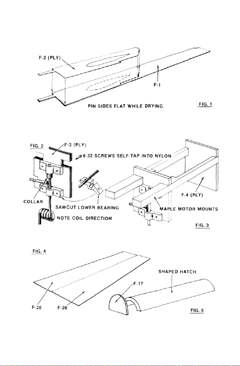
1. Glue
Fig.
1.
be
sub-assembled
F-2 (ply) doublers to F-l
first.
sides — make a left and a right side. See
2. Make sawcut in one nylon nosewheel bearing as shown and snap bearing
over the formed noseleg between the tiller-arm and the coil. Slip the collar over
the leg from the top, followed by the other nylon bearing. Screw the bearings
to 1/4" ply
F-3
using the 6-32 screws provided.
Fig
2 shows assembled unit
3. Glue F-3 and F-4 (ply) to the shaped motor mounts. See
Fig. 3.
4. Glue two F-20 pieces together as in Fig. 4. Use balsa cement for this joint,
Not white glue.
5. Join elevators with l/4"xl/2"x4" hardwood strip.
6. Glue F-17 to one end of shaped hatch block. See
7. Join parts of wing plan to make one-piece plan. Use
Fig. 5.
scotch tape and lots
of care.
2
Page 4
FUSELAGE
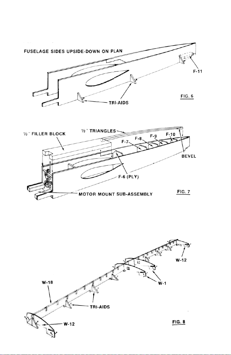
8. Pin F-ll in position on top view of fuselage. Pin both fuselage sides over
plan upside-down, and glue to
F-ll.
Use Tri-Aids as shown in
Fig. 6
to keep
sides vertical
9. Glue shaped tail block between sides at rear end. Glue F-6 thru F-10 in place.
10 . Glue motor-mount sub-assembly between sides See Fig. 7. Glue 1/2" x 2-3/4
x 11-7/8" block between sides and to
F-3 and F-4.
11. Glue 1/2" triangular longerons to sides and formers, cutting to scarf-
joint at rear end.
WING
12 Pin Tri-Aids to plan in pairs to support mainspars. Slip spars W-18 between
Tri-Aids
but
do
not
pin
to Tri-Aids or
to
plan.
Glue
spars together
at
center
joints only. See Fig. 8.
3
Page 5
13. Slip all ribs
W-l thru W-12
into spars egg-crate fashion.
Do not
glue joints
at this time! Pin all ribs over plan in correct alignment.
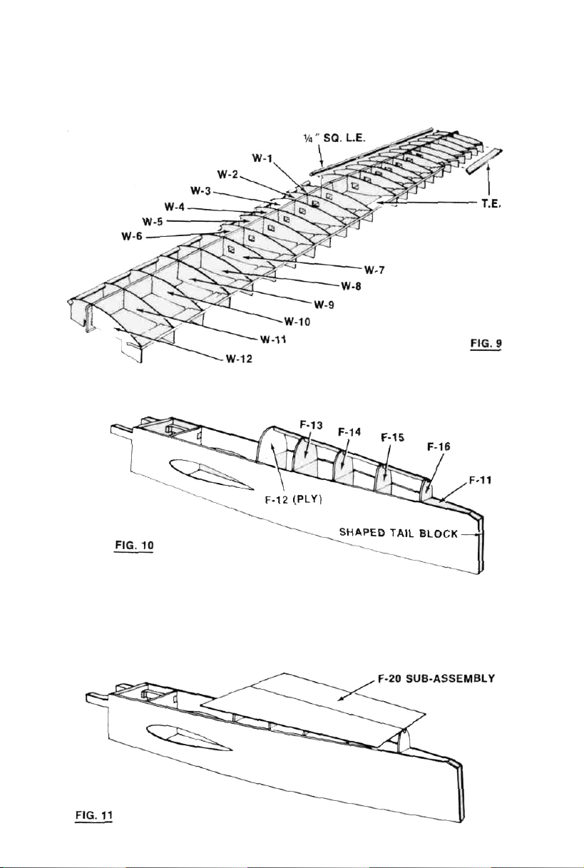
14. Glue 1/4" sq. L.E.'s into ribs, glueing center joint well. Slip bottom
sheets into slots in ribs. When satisfied with position, glue to ribs. See
T.E.
Fig. 9.
15. Use weights to hold structure down, making sure that all rib and spar
tabs are contacting table surface on plan properly. Run glue onto all rib-to-spar
joints.
FUSELAGE
16. Remove fuselage from plan. Glue
F-12
(ply) thru
F-16
in place, then 1/4" sq.
stringer. See Fig. 10.
17. Drill hole through F-17 and glue 1/8" dowel into hatch. Pin or tape hatch
in place on fuselage with dowel projecting through F-12. Drill F-18 (ply) with
1/4" drill at punchmark and slip over the dowel. Glue to F-12, making sure not
to get any glue on the dowel itself.
18. Glue the F-20 sub-assembly onto 1/4" sq. stringer centering the joint on
the stringer carefully. See
Fig. 11.
4
Page 6

WING
19. Cut L. E. Sheet doublers from 1/16"x3" sheet and glue in place on wing
from center to
clips or pins to hold L.E. joint while it dries. See
other side to spars and ribs.
W-5
. Glue 1/16" x 3" L. E. sheeting to L. E. first, using spring
Fig. 12.
Then glue and pin
20. Glue upper T.E. sheet in place. Glue in
l/16"x 1/4" rib capping strips.
MARK AND CUT LEVEL WITH TOP OF SIDES
FUSELAGE
21. At this time the rear turtledeck sheeting is attached. Follow the instructions
closely and you will have no trouble:
a) Dampen top of sheeting with water and let soak for a minute or two.
b) Bend sheeting down against formers.. Mark
the sides and trim for exact fit.
c) Run
hold with pins and tape while it dries.
white
glue into formers and sides. Pull sheet down each side and
W-15
and W-17, followed by all
FIG.
13
the sheet where it overlaps
d) Trim front and rear flush with
F-12 and F-16. See Fig. 13.
5
Page 7

22. Glue 1/8" ply patch F-21 into hatch as shown in Fig.
and mount nylon plate. Glue 1/2" x 3/4" x 1-3/8" hardwood block between motor
mounts: drill: and epoxy nylon ball fastener into hole. Adjust for proper fit.
23. Install engine. Glue top cowl block in place. Glue bottom front 3/8" block
to fuselage, then
in place.
24. Glue cowl side blocks in position, center F-19 around engine crankshaft and
glue. Remove engine. Glue servo tray mounts in place.
WING
25. Lift wing from plan. Turn upside-down, remove tabs and repeat instructions
19 and 20 (use parts W-16 and W-17). Glue 1/8" x 1/4" T. E. capping strip in
place. (Fig. 12). Trim and sand excess wood outside of
rib and glue on wingtip blocks.
26. Assemble aileron bellcranks to ply parts W-13. Glue
W-7 and
27. Run 1/16" music wire pushrods through wing ribs and assemble to bell-
cranks. Glue
W-8
F-5
(ply), and
respectively. Glue
W-14's
in position. Do not assemble connecting-links to bellcrank yet.
F-5A
(ply). Glue rear bottom 3/8" shaped block
W-13
in place in wing. See
14.
Drill 3/16" hole
W-12
until flush with
W-19
and
Fig. 15.
W-20
to ribs
FINAL ASSEMBLY
28. Try popping fuselage batch into place. Make any adjustments required
perfect fit.
29. Carve and sand fuselage blocks, cowl and wingtips to sections shown on
plan.
30. Slip metal clips onto main L. G. unit. Hold in position on
holes for mounting screws. Bolt L. G. in place, coating nuts inside with glue.
31. Slip flap horn into wing slots in fuselage sides and push to rear end. Slide
wing into slots and center the wing in the fuselage. It may be necessary to trim
away the front end of the wing slot on one side a little, to achieve this.
32. When satisfied with position, glue wing/fuselage joint using plenty of cement. Fill any oversize holes
carefully.
33. Sand stab and elevators to section and pin stab temporarily on fuselage,
lining up with the wing in front view. Glue tail blocks to fuselage over stab using
the fin temporarily as a 1/4" thick spacer. It will be easier to carve these blocks
to conform to fuselage lines without the stab and fin in place. After carving
blocks, sand fin and rudder to section and glue fin between block, and then glue
stab in place.
34. The R/C equipment is now installed. Screw the aileron servo in place
and hook up to pushrods. Sand ailerons and hinge onto the wing with MonoKote. These hinges are only temporary and will be removed before covering.
Install aileron connecting-links and horns. Check for movement using the radio.
with
vinyl-spackle (from hardware store) and sand
6
F-5 and
for a
drill
Page 8

35 Sand flaps and drill for flap horn (note offset — see plan). Install flaps
and hinge temporarily to wing
36 Mount three servos Make all pushrods as shown on plan Hinge rudder
and elevator Check all controls for free movement
37. Remove engine, R/C gear, landing gear main struts and all control surfaces
This model may be covered with Super MonoKote (follow instructions on
enclosed leaflet closely) or alternatively may be covered and finished using
silk and dope Hinge all control surfaces permanently after covering
38. Install fuel tank receiver, battery, wheels, engine and spinner, and cockpit
canopy Check CG (see plan for correct position) and if necessary move equipment fore or aft to get CG correct
FLYING
With a good 35 to 45-size engine the airspeed is a relatively constant 70
to 80 mph Automatic speed control is an advantage during maneuvering This
is achieved by propeller selection, airfoil, and flying weight of under 6 lbs
The planform of the plan, wing shape with swept leading edge and fuselage
profile provide excellent yaw stability and accurate roll response
The stunt flaps, which will be described later, contribute excellent lateral
stability
A nearly symmetrical plane and neutral stability coupled with efficient
or
large control surfaces produce the Nobler s maneuverability The rudder and
elevator are unusually large for a model airplane The ailerons are reflexing
trailing edge sections with sealed hinge gap giving rapid accurate linear response
with little drag Normal control surface movements are ailerons ± 10 degrees,
elevator ± 15 degrees, and rudder ± 30 degrees The coupled flaps move ±
5 degrees
For many years control line planes have had mechanically coupled flaps
and elevators to give them smoother flight and more lift in sharp corners The
same advantages apply with RC planes Control line models used equal coupled
flap and elevator movement, while the RC models should have much
less
flap
movement than elevator movement This is because of the inferior power/weight
ratio of RC models compared to CL models, and the consequent necessity to hold
down the drag to maintain flying speed
A radio controled model gains other advantages with flaps For example,
with more pitch axis power, we can have a more forward CG location for groovier
flying When deflected downward, the centersection of the wing is operating at
a higher angle of attack than the wing tips ensuring against tip stalling during
high g maneuvers or low speeds With the additional lift of the flaps the plane
needs less rotation about its pitch axis for a given response, thereby causing
less drag speed changes, and showing a smoother flight path The symmetrical
airfoil is, therefore, infinitely variable to obtain optimum performance
When landing or taking off, the flaps allow slower and more stable flight.
Even in gusty or windy weather, the Nobler seems to fly as if on rails The
flaps keep the wings extra stable because the wing tips are flying at a lower
angle of attack while the other features keep it tracking accurately Even though
the flaps are not sharply deflected, they provide a tremendous amount of additional
lift, even at low speeds
The technique of using flaps coupled with the elevator function is relatively
new to RC flying A detailed investigation of the performance with the flaps
and without the flaps has been made At the 1969 DCRC Symposium, Fred Marks
and Ed Sweeney presented a paper describing the technique showing the results
of
tests and experiments with several airplanes To make their findings meaningful,
7
Page 9

a system of in-flight uncoupling of the flap function was devised Maneuvers with
these planes, including of course the RC Nobler, could be made with and
without coupled flaps When uncoupled, the flaps were positioned at neutral
Without question, maneuvers with flaps are smoother, can be tighter, can be
slower, the plane is definitely more stable, and safer The Nobler is a fine
stunt plane without coupled flaps, but like all the other models, it is noticeably
better and more enjoyable with flaps
One finding of the study was that since the coupled flaps offer very little
drag during flare out for landing, the models would generally float in ground
effect With a slow idling engine or with the 10x5 Top Flite and 10x6 Top Flite
or Power Prop on the Noblers, this is no problem, but can be a nuisance
with higher pitch props or a fast idle By uncoupling the flaps, the models
landed as usual at a high sink rate and higher speeds We could also lower
the flaps independently 25 degrees for landing In gusty or windy conditions we
use only 15 degrees deflection for landing Extra flap movement gives higher lift
at slow speeds with adequate drag for precise spot landings This feature is worthwhile if you have a five channel system and five servos.
Uncoupling may be achieved in the transmitter by adding a switch and
potentionmeter in the fifth channel circuit The pot is ganged with or rotated
simultaneously with the elevator stick movement, the switch transfers the fifth
channel control to the ganged pot for coupled flaps and elevator or to the normal
fifth channel control pot for independent flap operation Set linkages in the
transmitter to give the ganged pot one third the rotation of the regular pot.
Now, when ganged, the flap has ± 5 degrees movement, and when operated
independently, it has 25 degrees movement downward See Fig. 16.
ELECTRONIC COUPLING
FIG.
16
Note Flap neutral is at 80°
servo position 0' 80°
is landing flap range,
100° to 60° is coupled
flap range
These leads were originally
wired only to the 5th
channel pot
8
Page 10

Another method to get landing flap operation with a 5 channel system is use
a
linkage
in the plane similar
to
the elevator trim arrangement of reed
control
systems A five servo installation is needed Make a "trim bar" between elevator
and flap servo See FIG. 17. Landing flap mode can be set up with four channel
systems by coupling with the throttle servo, but it has not been proven out yet
MECHANICAL COUPLING
Elev
Elev Servo
Coupling Bar as in reed systems
Trim Bar There are many ways to
accomplish this method
5th Channel Servo
Flap
Note Servo is at 100° position
lor stunting Move toward
0° for landing flap position
FIG.
17
PREPARATION FOR FLYING EXPERT
As mentioned earlier, the control surfaces should have the following movements ailerons ± 10 degrees, elevator ± 15 degrees rudder ± 30 degrees, and
flaps ± 5 degrees. This flap/elevator coupling is the same whether mechanical
or electronic systems are used If landing flap mode is available, the flaps should
go down to 25 degrees.
The Center of Gravity should be measured (without fuel in the tank) at
6 to 7 inches forward of the hinge line on the wing Move the battery pack
around to achieve this Set up the surfaces with transmitter trims in neutral,
then apply up-trim at the transmitter to hold level flight or give a slight climb
Although the engine is well cowled, it is adequately cooled even with a
muffler Have a full fuel tank on the first flights Use a 10 x 5 Top Flite propeller,
after a few flights accomplished, go to a 10x6 Top Flite Power prop
As the model sits level on the ground, a positive rotation is required for
lift-off From grass use a slightly oversized nose wheel to have a positive angle
of attack As an expert flyer, you already know how to trim a model Make
several short flights adjusting the clevises to move the transmitter sticks back
to neutral The model should be adjusted for level hands-off flight upright and
with down trim applied for inverted flight Make these checks at 3/4 throttle
At take-off, propeller slipstream effect gives a left yaw Compensate with
rudder keeping the wings level with ailerons, if necessary Once you have accelerated well past stall speed, the yaw disappears Side thrust can introduce
more problems than it is worth on stunt ships With the
Nobler,
it is easily
accounted for by the effective rudder
When landing, the model is stable and amazingly slow Avoid the floating
in ground effect by closing the throttle during the downwind leg of your landing
approach when the plane is exactly opposite the landing area. Full stall landings
are best.
9
Page 11

PREPARATION FOR FLYING
R/C Nobler
pretty good trainer too
Before going to the flying field, adjust the control surface movements
± 5 degrees on ailerons, ± 10 degrees on elevator,
der.
Set the flaps at a fixed position 25 degrees
settings with transmitter trims at neutral Then before flying, apply full down
trim This compensates for the extra lift from the flaps
Set the Center of Gravity at 7 inches forward of the hinge line on the wing
(with the fuel tank empty) Use a 10x5 Top Flite propeller
Flying hints Hold a bit of up elevator on the stick to make the takeoff, use
full throttle After takeoff throttle back to 1/2 speed and climb in very wide
shallow bank turns to gain altitude Now, trim the
straight flight adjust the elevator trim for level flight if necessary Make slow
gentle movements on the control stick Remember, you must bank into a turn
and when you want to fly straight again, you must bank out of the turn Keep
all banks at less than 10 degrees angle Make wide turns in both directions
The R/C
down If it stalls, it will drop forward Let it drop a few feet then apply a bit
of up elevator to level flight and release the elevator pressure Next time,
before the stall, apply a quick dab of down elevator to prevent the stall
Try a few short power-off glides in the first flight while well up in the sky.
In level flight, throttle back slowly to idle Notice the speed and angle at which
the Nobler glides The model should be slow, verv slightly nose down and steady
To climb up again, open the throttle Repeat the glide and climb several times
Try some gentle turns while gliding If the engine stops unexpectedly, concentrate
on a landing with wings level letting it assume its normal glide speed
It is now time to land It would be nice to land back on the runway,
but don't try too hard to get on the runway Just keep the wings level at touchdown
wherever it is Use the same power off glide as when up high Steer around while
gliding trying to land nearby When the plane gets below 10 feet in an approach,
it is best to land no matter where you are The R/C Nobler is pretty slow in
the glide with flaps down so it will be safe In other words, if you want to try the
landing again, apply full throttle before getting to 10 foot altitude
is a full stunt plane but because of certain features it is a
It is always best to have an expert help you learn to fly.
Nobler
will keep a slow steady stable flying speed with those flaps
NOTICE
and ± 20
down from neutral.
degrees on rud-
ailerons and rudder
for
Do these
for
R/C NOBLER ACROBATICS
The quality of acrobatics depends upon the pilot much more than on the
plane With the Nobler, you will probably enjoy stunting more than with most
other planes This is because of its linear responses, neutral stability, and ability
to fly through smaller maneuvers at slower speeds It has all the ability to win
contests, but winning is up to you
If you are planning on contest work, we suggest you set elevator trim for
slight dive This prevents ballooning after each maneuver and strings out the
rolling maneuvers Very little down elevator is needed during the inverted portions
of the rolls If you are just sport flying, trim for level flight
LOOPS: Enter with full throttle and adjust size for constant flying speed
throughout Big loops or small loops can be done
ROLLS: Use slight down when inverted during consecutive rolls and a bit
more during slow or point rolls
Nobler
does not need top rudder during any rolls.
10
Page 12

WING OVERS: Make the climb at half throttle and do the turn at l/4th
throttle Turns easily either way
CUBAN EIGHTS: In any Cuban eight maneuver use large loops so that
the half rolls can be accurately placed at the intersections, use full aileron for
the
rolls
Ease
off
the
elevator
for fun, try two-point rolls with full top rudder in the Cuban eights
KNIFE EDGE: Enter from level fight and apply rudder simultaneously with
the quarter roll Hold full rudder The Nobler will not drop its nose or loose
altitude If you enter with a climb, the plane will climb throughout
SPINS: Due to the extra stability with flaps, use ailerons in the direction
of the spin The rate of rotation is not fast but can be controled with the ailerons
To regain normal flight release either or both rudder and elevator, recovery is
instant
coming
over
the top before starting the roll Just
LENCHEVICK:
right (or left) turn at 45 degrees climb and bank Use full throttle throughout
While climbing make left (or right) aileron/rudder/up-elevator snap roll so that
the plane is spinning and still going up After one good spin move elevator stick
to down position while maintaining rudder and aileron directions Plane will begin
to tumble a moment later The tumble is not necessarily head-over-tail but
probably diagonal After tumbling which is the desired maneuver, release the
sticks and recover If the stick positions are held, the model will exit the tumble
in an inverted spin
SNAP
left / left combinations but for outside or inverted snaps use left / right or
right / left combinations of rudder and ailerons Precision snaps can also be done
with Nobler, including half snaps
SIDE SLIPS: Rudder is powerful and fuselage offers plenty of side area
so the side slip is effective in checking a landing overshoot In flight,
can do a flat turn by applying full rudder one way and keeping the wings level
with aileron
SQUARE AND TRIANGULAR LOOPS: Because of ths airfoil and flaps,
the
Nobler
and triangles, etc There is no wobbling because of no tip stalling during high lift
demands On the decending side of the square-type maneuvers throttle back
to low speed The corner will be just as sharp as when going up at full
throttle
We wish you all the best of luck with your
ROLLS: Use rudder and aileron together For inside snaps, use
Nobler
is safe in "high G" maneuvers as at corners of square loops, top hat,
Nobler
does it but it takes timing Enter from climbing
will make a wide turn, looks strange, but works.
Nobler.
ED
SWEENEY
FRED
MARKS
you
Top Flite Models recommends that any newcomers to RC model flying
join the AMA (See Page 1 for details) Among the many benefits, the member
will receive a Rule book describing with diagrams the competition maneuvers,
and will be insured against any peisonal liability claim as a result of flying mishaps
mishaps
11
Page 13

The covering with
the built-in finish
MonoKote, acclaimed the greatest advance in covering
and finishing in model building history, will give you a
professional looking
eliminating the usual tedious work of sealing, doping,
sanding and polishing.
MONOKOTE
finish
in a fraction
of
the normal time,
Just lay on MonoKote.
Seal edges with an
electric Iron.
LIGHT ... Is 2/3 lighter than an
equivalent silk and dope finish.
STRONG . . . has a tensile strength of
25,000 Lbs. per Sq. In.
PUNCTURE RESISTANT ... has many
times the tear-strength of silk and
dope finishes, yet should it puncture,
SUPER MONOKOTE
This material has a totally dry adhesive, activated by the heat of an Iron. For
best results use the MonoKote. Sealing iron shown. Recommended for all basic
covering of the model.
Opaque Colon:
REGULAR MONOKOTE
This material has a sticky adhesive and is recommended for trim areas
color scheming, etc. No ironing required; it's just pressed down on
basic covering.
Missile Red
Int. Orange
Piper Yellow
Jet White
Instant, almost Invisible repairs can
be made on the field.
ODORLESS . . . Completely odorless,
eliminates irritating smells and dangerous fumes.
MOISTURE PROOF . . . STAIN PROOF
. . . FADE PROOF . . . FUEL PROOFI
Mustang Alum.
Sky Blue
Insignia Blue
Midnight Black
MONOKOTE
Shrink skin tight
with heat.
Metallics:
Emerald Green
Electric Blue
Transparents:
Solar Red
Sunset Orange
Sunrise Yellow
Sealing
Iron
Page 14

S.
E.
5.
a
Never before has an R/C scale model been
designed with such attention to the most insignificant detail Wing Span 52" Eng 45
to
.60 Kit
RC-13
TAURUS -
NOW includes ailerons & fittings Multi channel
trainer Span 57' Eng 15.45 Kit RC-4
KWIK-FLI III
World and twice Nats winner Designed
by Phil Kraft Span 60 Eng 45 to 61
Includes T A C —Ready made wing fixture
Kit
RC-12
WINNER OF THE
1962 NATIONALS
TAURUS
Most precise and complete R/C kit ever produced.
Span-70 Eng 45 Kit RC 7
TAURUS WING KIT-RC 7W 13.95
/
HEADMASTER
NYLON
THE PROPS OF CHAMPS A size for every flying
requirement TOP FLITES and POWER PROPS
have been used by more NATIONALS and WORLD
CHAMPIONS than any other brand Each prop is
perfectly balanced and aerodynamically designed
for maximum thrust
TOP DAWG
Suitable for escapement, servos galloping ghost,
reeds or even proportional gear TAC construction Wingspan 39 5"—Length 32" Engines 049
15
Kit
No
RC
10
SCHOOLGIRL
One wing or two Span
32 Engines 020 049
Kit
RC
9
SCHOOLMASTER
Single or multi channel
with rudder elevator
and engine control
Span 39 Eng 049 090
Kit
RC
8
 Loading...