

Page 1

GLS-2000
SERIES
LASER SCANNER
INSTRUCTION MANUAL
64652 90261
Page 2

i
HOW TO READ THIS MANUAL
Thank you for selecting the TOPCON instrument.
• Please read this instruction manual carefully, before using this product.
• The specifications and general appearance of the instrument are subject to change without prior notice
and without obligation by TOPCON CORPORATION and may differ from those appearing in this
manual.
• The content of this manual is subject to change without notice.
• Some of the diagrams shown in this manual may be simplified for easier understanding.
• This manual is protected by copyright and all rights are reserved by TOPCON CORPORATION.
• Except as permitted by Copyright law, this manual may not be copied, and no part of this manual may
be reproduced in any form or by any means.
This manual may not be modified, adapted or otherwise used for the production of derivative works.
Symbols
The following conventions are used in this manual.
: Indicates precautions and important items which should be read before operations.
: Indicates the chapter title to refer to for additional information.
: Indicates supplementary explanation.
[OK] etc. : Indicates buttons on the display.
Notes regarding manual style
• All company and product names featured in this manual are trademarks or registered trademarks of
each respective organization.
Li-ion
S Li-ion
Page 3

ii
CONTENTS
1. PRECAUTIONS FOR SAFE OPERATION .............................................. 1
2. PRECAUTIONS ....................................................................................... 3
3. LASER SAFETY INFORMATION ............................................................ 6
4. PRODUCT OUTLINE............................................................................... 8
4.1 Parts of the Instrument .................................................................. 8
4.2 Operating Keys ........................................................................... 10
4.3 Display and Functions of the Main Menu .................................... 11
4.4 Flow of the Screens .................................................................... 12
5. PREPARATIONS BEFORE USE........................................................... 13
5.1 Inserting an SD memory card and Installing the Battery ............. 13
5.2 Connecting the External Power Source ...................................... 16
5.3 Overview of Scanning Procedure ................................................ 17
6. PREPARATION FOR MEASUREMENT................................................ 18
6.1 Detaching / attaching the Handle ................................................ 18
6.2 Detaching / attaching the Tribrach .............................................. 18
6.3 Power ON/OFF ...........................................................................19
6.4 Setting Up the Instrument ........................................................... 21
6.5 Using the SD Card ...................................................................... 23
6.6 Battery Power Remaining Display ............................................... 24
6.7 Replacing the Batteries during the power is ON ......................... 25
6.8 Entering Numeric and Alphabetic Characters ............................. 26
6.9 Preparing the Target .................................................................... 27
Assembling the target .................................................................. 27
7. INSTRUMENT SETTINGS..................................................................... 29
7.1 Setting the Tilt Sensor ON/OFF .................................................. 29
7.2 Camera Settings (Angle of view and Resolution) ........................ 31
7.3 Settings for Scanning Conditions ................................................ 32
7.4 Measuring Distance to the Target Measurement Object ............. 35
8. FLOW OF THE CONFIGURATION SCREEN ....................................... 37
8.1 Setting Temperature and Atmospheric Pressure ........................ 39
8.2 Setting the Prism Constant and Flash Light ................................ 40
8.3 Setting the Date and Time ........................................................... 41
8.4 Displaying the Last Calibration Date ........................................... 42
8.5 Adjusting the Brightness of the Display Section .......................... 43
8.6 Setting the Volume ...................................................................... 44
8.7 Selecting the Unit ........................................................................ 45
8.8 Selecting the Coordinate System ................................................ 46
8.9 Handling the Coordinate Point File ............................................. 47
Import the coordinate point file .................................................... 47
Conditions to create the CSV file (coordinate point file) .............. 47
8.10 Data structure in the SD card ...................................................... 50
9. STATION SETTINGS............................................................................. 51
9.1 Creating a New Station ............................................................... 52
Page 4

iii
CONTENTS
9.2 Setting the Point Name (Occupied point and Backsight point) .. 53
When using the known point ........................................................ 53
Importing the point name (Occupied point or Backsight point) .... 57
10. MEASURING (SCANNING) ................................................................... 59
10.1 Target Scanning .......................................................................... 60
Recommended search width setting ............................................ 63
Setting the target height ............................................................... 63
10.2 3D Scanning ................................................................................ 64
Scanning range ............................................................................ 64
Performing 3D range setting scanning ........................................ 65
Performing 3D whole circumference scanning ............................ 68
10.3 View the Data on the SD Card .................................................... 70
11. CHECKS AND ADJUSTMENTS ............................................................ 71
11.1 Circular Level Adjustment ........................................................... 71
11.2 Tilt Sensor Calibration ................................................................. 72
11.3 Aligning the Laser Plummet Beam with the Instrument Center ... 73
11.4 Aligning the Center of the Instrument and that of the Image ....... 75
12. BATTERY CHARGING .......................................................................... 77
12.1 Battery Charging ......................................................................... 77
13. HOW TO STORE ................................................................................... 79
14. OPTIONAL ACCESSORIES .................................................................. 80
15. WARNING AND ERROR MESSAGES .................................................. 81
15.1 Error ............................................................................................81
15.2 Warning ....................................................................................... 82
16. SPECIFICATIONS ................................................................................. 84
17. REGULATIONS ..................................................................................... 87
Page 5

1
1. PRECAUTIONS FOR SAFE OPERATION
For the safe use of the product and prevention of injury to operators and other persons as well as
prevention of property damage, items which should be observed are indicated by an exclamation point
within a triangle used with WARNING and CAUTION statements in this instruction manual.
The definitions of the indications are listed below. Be sure you understand them before reading the
manual’s main text.
Definition of Indication
General
WARNING
Ignoring this indication and making an operation error could possibly result in death
or serious injury to the operator.
CAUTION
Ignoring this indication and making an operation error could possibly result in
personal injury or property damage.
This symbol indicates items for which caution (hazard warnings inclusive) is urged. Specific
details are printed in or near the symbol.
This symbol indicates items which are prohibited. Specific details are printed in or near the
symbol.
This symbol indicates items which must always be performed. Specific details are printed in
or near the symbol.
Warning
Do not use the unit in areas exposed to high amounts of dust or ash, in areas where there is
inadequate ventilation, or near combustible materials. An explosion could occur.
Do not perform disassembly or rebuilding. Fire, electric shock, burns, or hazardous radiation
exposure could result.
Because this instrument is heavy, make sure to carry it carefully using both the handle and
the side handle. There is a possibility that the instrument may topple and fall resulting in
possible injury, and incorrect lifting posture may also result in hurting your back.
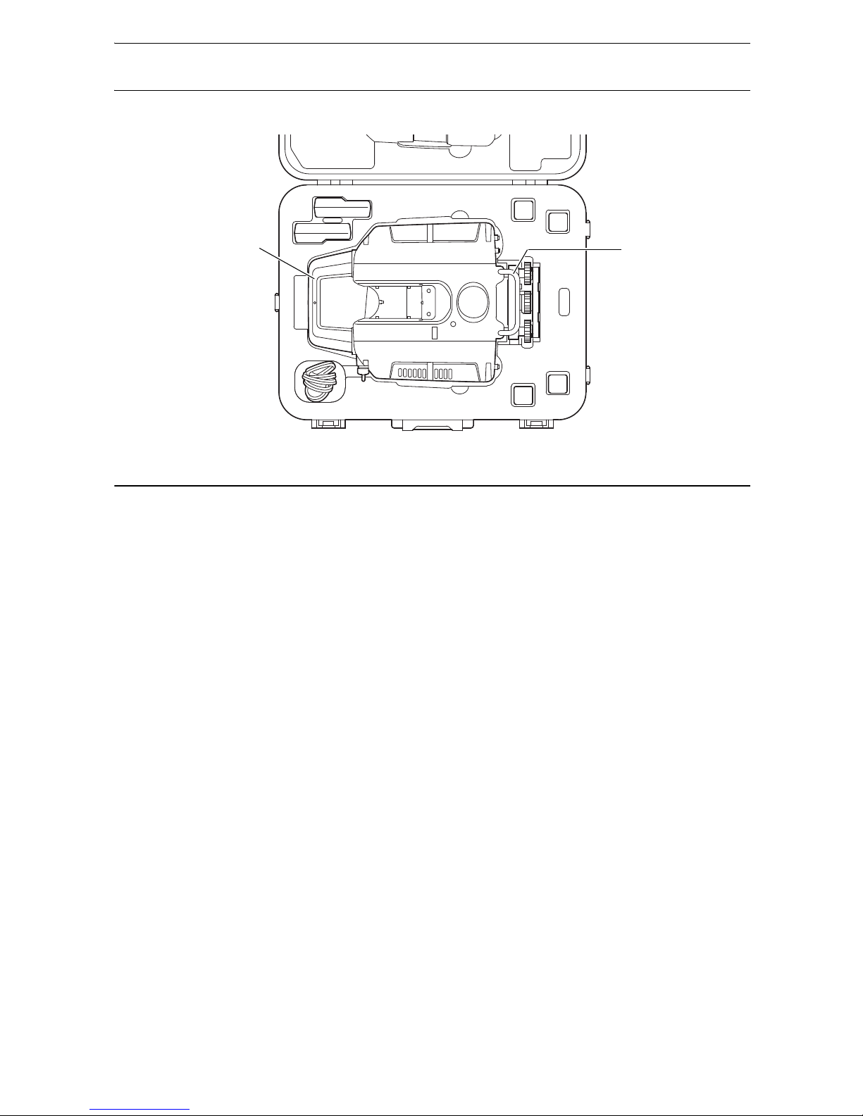
When securing the instrument in the carrying case make sure that all catches, including the
side catches, are closed. Failure to do so could result in the instrument falling out while being
carried, causing injury.
When scanning the target with the flash light while the instrument is set to use the prism,
please pay attention to the surroundings before doing so. When the target scanning is started
with the flash light while the instrument is set to use the prism, a white spot beam will be
emitted from the scanner unit to detect the position of the prism. This spot beam may
decrease a driver or pedestrian's vision temporarily if it hits the eye and may cause a serious
accident.
Secure handle to main unit. Failure to properly secure the handle could result in the unit falling
off while being carried, causing injury.
Caution
Do not use the carrying case as a footstool. The case is slippery and unstable so a person
could slip and fall off it.
Do not place the instrument in a case with a damaged catch, belt or handle. The case or
instrument could be dropped and cause injury.
Do not touch the instrument while the motor is in operation. Injury could result.
Page 6

2
1. PRECAUTIONS FOR SAFE OPERATION
Power Supply
Tripod
Do not touch the scanner section during high-speed rotation. Injury could result.
Tighten the adjustment tribrach clamp securely. Failure to properly secure the clamp could
result in the tribrach falling off while being carried, causing injury.
Warning
Do not short circuit. Heat or ignition could result.
Do not place articles such as clothing on the battery charger while charging batteries. Sparks
could be induced, leading to fire.
Do not use voltage other than the specified power supply voltage. Fire or electrical shock
could result.
Do not use batteries other than those designated. An explosion could occur, or abnormal heat
generated, leading to fire.
Do not use damaged power cords, plugs or loose outlets. Fire or electric shock could result.
Do not use power cords other than those designated. Fire could result.
Use only the specified battery charger to recharge batteries. Other chargers may be of
different voltage rating or polarity, causing sparking which could lead to fire or burns.
Do not use the battery or charger for any other equipment or purpose. Fire or burns caused
by ignition could result.
Do not heat or throw batteries or chargers into fire. An explosion could occur, resulting in
injury.
To prevent shorting of the battery in storage, apply insulating tape or equivalent to the
terminals. Otherwise shorting could occur resulting in fire or burns.
Do not use batteries or the battery charger if wet. Resultant shorting could lead to fire or burns.
Do not connect or disconnect power supply plugs with wet hands. Electric shock could result.
Caution
Do not touch liquid leaking from batteries. Harmful chemicals could cause burns or blisters.
Caution
When mounting the instrument to the tripod, tighten the centering screw securely. Failure to
tighten the screw properly could result in the instrument falling off the tripod, causing injury.
Tighten securely the leg fixing screws of the tripod on which the instrument is mounted.
Failure to tighten the screws could result in the tripod collapsing, causing injury.
Do not carry the tripod with the tripod shoes pointed at other persons. A person could be
injured if struck by the tripod shoes.
Keep hands and feet away from the tripod shoes when fixing the tripod in the ground. A hand
or foot stab wound could result.
Tighten the leg fixing screws securely before carrying the tripod. Failure to tighten the screws
could lead to the tripod legs extending, causing injury.
Page 7

3
2. PRECAUTIONS
Charging Battery
• Be sure to charge the battery within the charging temperature range.
Charging temperature range: 0 to 40°C
Warranty policy for Battery
• Battery is an expendable item. The decline in retained capacity depending on the repeated charging/
discharging cycle is out of warranty.
Precautions concerning water and dust resistance
The instrument conforms to IP54 specifications for waterproofing and dust resistance when battery cover,
connector cap and the Wide-angle camera lens cap of the instrument and are closed.
• Be sure to correctly attach the connector caps to protect the instrument from moisture and dust particles
when the connector is not in use.
• Make sure that moisture or dust particles do not come in contact with the terminal or connectors.
Operating the instrument with moisture or dust on the terminal or connectors may cause damage to the
instrument.
• Make sure that the inside of the carrying case and the instrument are dry before closing the case. If
moisture is trapped inside the case, it may cause the instrument to rust.
• If there is a crack or deformation in the rubber packing for the battery cover, stop using and replace the
packing.
• To retain the waterproof property, it is recommended that you replace the rubber packing once every
two years. To replace the packing, contact your local sales dealer.
The Lithium Battery
• The lithium battery is used to maintain the Calendar & Clock function. It can back up data for
approximately 5 years of normal use and storage (Temperature = 20°, humidity = about 50%), but its
lifetime may be shorter depending on circumstances.
The Levelling Base
• Always use the levelling base provided.
If the tribrach is installed incorrectly, the measuring precision could be effected. Occasionally check the
adjusting screws on the tribrach. Make sure the base fixing lever is locked and the base fixing screws
are tightened.
Tripod
• When mounting the instrument on a tripod, use a wooden tripod.
Do not use a metallic tripod.
Heat Release
• To prevent malfunction caused by a temperature rise inside this instrument, heat vents are provided to
release heat. Do not cover the vents when in use. When installing this instrument, keep the vents away
from a wall.
Heat vents
Heat vents
Page 8
4
2. PRECAUTIONS
Removing the instrument
• When removing the instrument from the case, hold by the handle and side handle and pick it up while
keeping it level.
Other precautions
• Effect of water drops
It may not be possible to measure if there are water drops on the glass of the scanner unit. Wipe off
moisture completely. A wet object may not be measured.
• When raining or snowing
When it is raining, snowing or foggy outside, please do not use the instrument to measure objects. Water
drops and snowflakes will be recognized as 3D data.
• Horizontally rotating part
Do not turn the horizontally rotating part and the scanner unit with your hands while the power is ON.
If it has been turned by force, turn the power ON again. (Except when collimating)
• Guarding the instrument against shocks
When transporting the instrument, provide some protection to minimize risk of shocks. Heavy shocks
may cause the measurement to be faulty.
• Sudden changes of temperature
Any sudden change of temperature to the instrument may result in a reduction of measuring distance
range, i.e when taking the instrument out from a heated vehicle. Let instrument acclimate itself to
ambient temperature.
• Direct sunlight
Do not expose the instrument to direct sunlight for extended periods of time. When left in the sun for
long periods, performance may be adversely affected, or if the inner temperature of the instrument may
rise to an abnormally high level, the instrument may fail to operate.
When measurements must be made in locations exposed to the sun and require high precision, protect
from direct sunlight by using a sunshade for the instrument and tripod.
• Battery level check
Confirm battery level remaining before operating.
• Battery use
Always use four batteries as one set, and operate the instrument with batteries that have been charged
and discharged the same number of times. Do not mix old and new batteries, or batteries that have been
charged and discharged a different number of times.
• Taking the battery out
It is recommended not to take the battery out during the power is on. Doing so may cause loss of data.
Please do your assembling or taking the battery out after the power is off. Refer to Chapter “Replacing
the Batteries during the power is ON” on page 25 if you need to replace the batteries during the power
is on.
Side handle
Handle
Page 9

5
2. PRECAUTIONS
Maintenance
• Wipe off moisture completely if the instrument gets wet during survey work.
• Always clean the instrument before returning it to the case. The scanner unit, wide-angle camera lens
and laser plummet window, etc. require special care. First, dust it off with the lens brush to remove tiny
particles. Then, after providing a little condensation by breathing on the lens, wipe it with the wiping
cloth.
• If the display is dirty, carefully wipe it with a soft, dry cloth. To clean other parts of the instrument or the
carrying case, lightly moisten a soft cloth in a mild detergent solution. Wring out excess water until the
cloth is slightly damp, then carefully wipe the surface of the unit. Do not use any alkaline cleaning
solutions, alcohol, or any other organic solvents on the instrument or display.
• Store the instrument in a dry room where the temperature remains fairly constant.
• Check the tripod for loose fit and loose screws.
• If a foreign object is thought to be in the rotation section or the screw section of this instrument, or if a
trace of water droplets or mold is found on the scanner unit, or the reflecting prism of the scanner,
contact your local dealer.
• When the instrument is not used for a long time, check it at least once every 3 months.
• When removing the instrument from the carrying case, never pull it out by force. The empty carrying
case should be closed to protect it from moisture.
• Check the instrument for proper adjustment periodically to maintain the instrument accuracy.
Exporting this product (Relating EAR)
• This product is equipped with the parts/units, and contains software/technology, which are subject to the
EAR (Export Administration Regulations). Depending on countries you wish to export or bring the
product to, a US export license may be required. In such a case, it is your responsibility to obtain the
license. The countries requiring the license as of May 2013 are shown below. Please consult the Export
Administration Regulations as they are subject to change.
North Korea
Iran
Syria
Sudan
Cuba
URL for the EAR of the US: http://www.bis.doc.gov/policiesandregulations/ear/index.htm
User
• This product is for professional use only!
The user is required to be a qualified surveyor or have a good knowledge of surveying, in order to
understand the user and safety instructions, before operating, inspecting or adjusting.
• Wear the required protectors (safety shoes, helmet, etc.) when operating.
Exceptions from responsibility
• The user of this product is expected to follow all operating instructions and make periodic checks
(hardware only) of the product’s performance.
• The manufacturer, or its representatives, assumes no responsibility for results of faulty or intentional
usage or misuse including any direct, indirect, consequential damage, or loss of profits.
• The manufacturer, or its representatives, assumes no responsibility for consequential damage, or loss
of profits due to any natural disaster, (earthquake, storms, floods etc.), fire, accident, or an act of a third
party and/or usage under unusual conditions.
• The manufacturer, or its representatives, assumes no responsibility for any damage (change of data,
loss of data, loss of profits, an interruption of business etc.) caused by use of the product or an unusable
product.
• The manufacturer, or its representatives, assumes no responsibility for any damage, and loss of profits
caused by usage different to that explained in the operator’s manual.
• The manufacturer, or its representatives, assumes no responsibility for damage caused by incorrect
operation, or action resulting from connecting to other products.
Page 10
6
3. LASER SAFETY INFORMATION
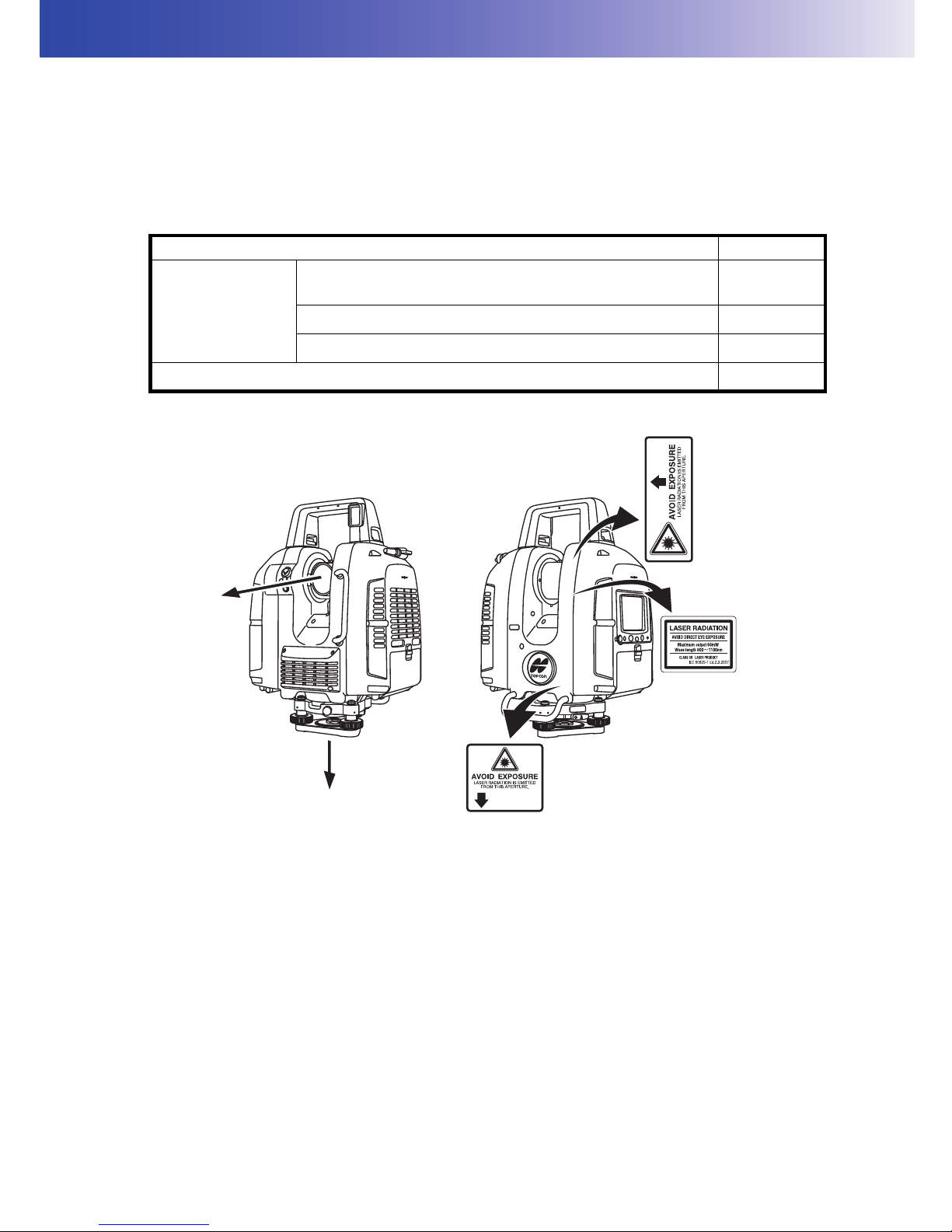
This instrument emits a laser beam while scanning or using a laser plummet.
The instrument is classified as the following class of Laser Product according to IEC Standard
Publication 60825-1 Ed.2.0: 2007 and United States Government Code of Federal Regulation FDA
CDRH 21CFR Part 1040.10 and 1040.11 (Complies with FDA performance standards for laser
products except for deviations pursuant to Laser Notice No.50, dated June 24, 2007.)
Laser class of each mode is as follows.
Warning
• Use of controls or adjustments or performance of procedures other than those specified herein may
result in hazardous radiation exposure.
• Never intentionally point the laser beam at another person. The laser beam is injurious to the eyes and
skin. If an eye injury is caused by exposure to the laser beam, seek immediate medical attention from
a licensed ophthalmologist.
• Do not look directly into the laser beam. Doing so could cause permanent eye damage.
• Do not stare at the laser beam. Doing so could cause permanent eye damage.
• Never look at the laser beam through a telescope, binoculars or other optical instruments. Doing so
could cause permanent eye damage.
Caution
• Perform checks at start of work and periodic checks and adjustments with the laser beam emitted under
normal conditions.
• When the instrument is not being used, turn off the power.
• When disposing of the instrument, destroy the battery connector so that the laser beam cannot be
emitted.
Device Laser class
Scanner unit
Range mode
(“Detail” / ”High Speed” / ”Standard“ / ”Close“ is selected.)
Class 3R
Range mode (“Low Power“ is selected.) Class 1M
Laser pointer Class 3R
Laser Plummet Class 3R
Laser beam
emitted from here
Page 11

7
3. LASER SAFETY INFORMATION
• Avoid setting the instrument at heights at which the path of the laser may strike pedestrians or drivers
at head height. Operate the instrument with due caution to avoid injuries that may be caused by the
visible laser beam unintentionally striking a person in the eye.
• Only those who have received training as per the following items shall use this product.
• Read this manual for usage procedures for this product.
• Hazardous protection procedures (read "LASER SAFETY INFORMATION")
• Requisite protective gear (read "LASER SAFETY INFORMATION")
• Accident reporting procedures (stipulate procedures beforehand for transporting the injured and
contacting physicians in case there are laser-induced injuries).
• Persons working within the range of the laser beam are advised to wear eye protection which
corresponds to the laser wavelength of the instrument being used.
• Areas in which the laser is used should be posted with a standard laser warning sign.
• When using the laser-pointer function, be sure to turn OFF the output laser after distance measurement
is completed.
Page 12
8
4. PRODUCT OUTLINE
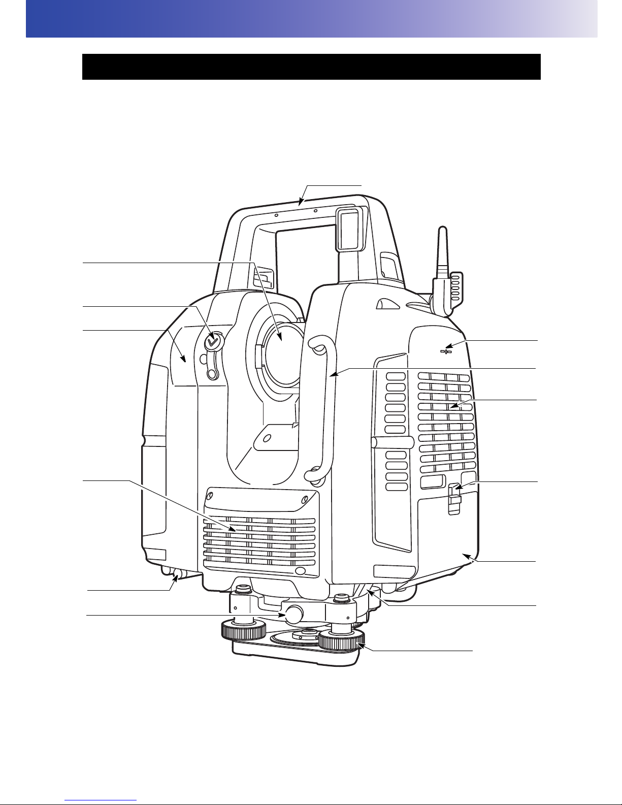
4.1 Parts of the Instrument
Side handle
Battery
cover lever
Wide-angle camera
(with lens cap)
Levelling base locking screw
Battery
cover Left
Battery connector
Leveling screw
Handle
Scanner unit (laser aperture)
and
Camera (telescope)
Heat vents
Stylus (pen)
Instrument
height mark
Heat vents
Sighting collimator
Page 13
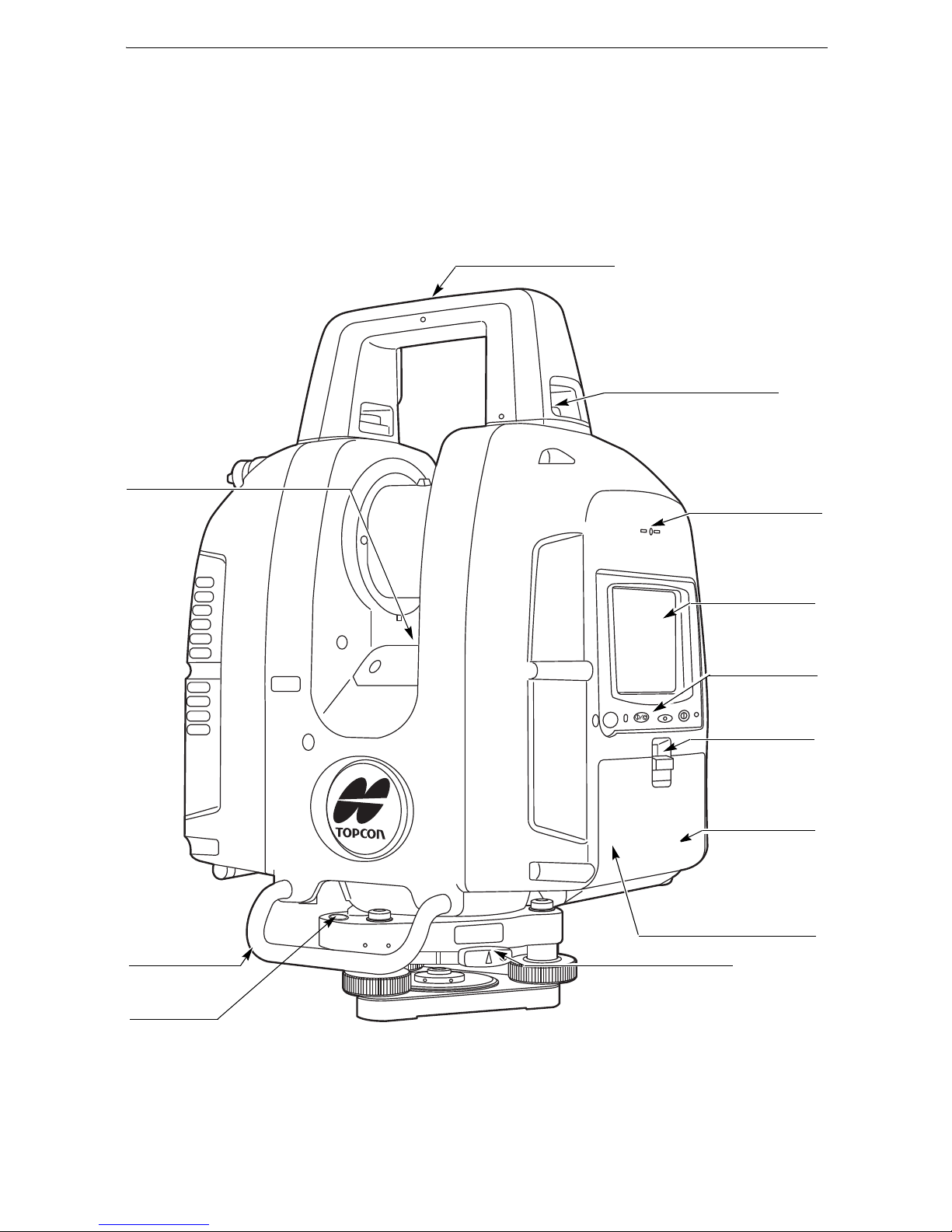
9
4. PRODUCT OUTLINE
Display
Operation key
Battery cover
lever
Battery cover
Right
Tribrach fixing lever
Side handle
Instrument height
mark
Handle locking screw
Card slot
(inside of a battery cover)
Circular level
Laser plummet
window
Instrument center mark
Page 14
10
4. PRODUCT OUTLINE
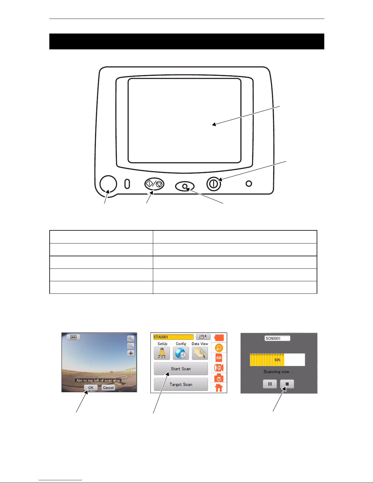
The operating keys on the side of the instrument are as follows:
• The buttons in the screens below provide the same functions as the keys listed in the table above.
4.2 Operating Keys
Key / Indicator name Function
Collimating Position Setting key Sets the collimating position.
Start/Stop Scan key Starts or stops scanning.
Power key Turns the power ON and OFF.
Power Indicator Lighting up in orange when the power is turned ON.
Collimating Position Setting key Start/Stop Scan key
Power key
Screen
Power Indicator
Start Scan button
Scan Stop key
Collimating Position Setting key
Page 15
11
4. PRODUCT OUTLINE
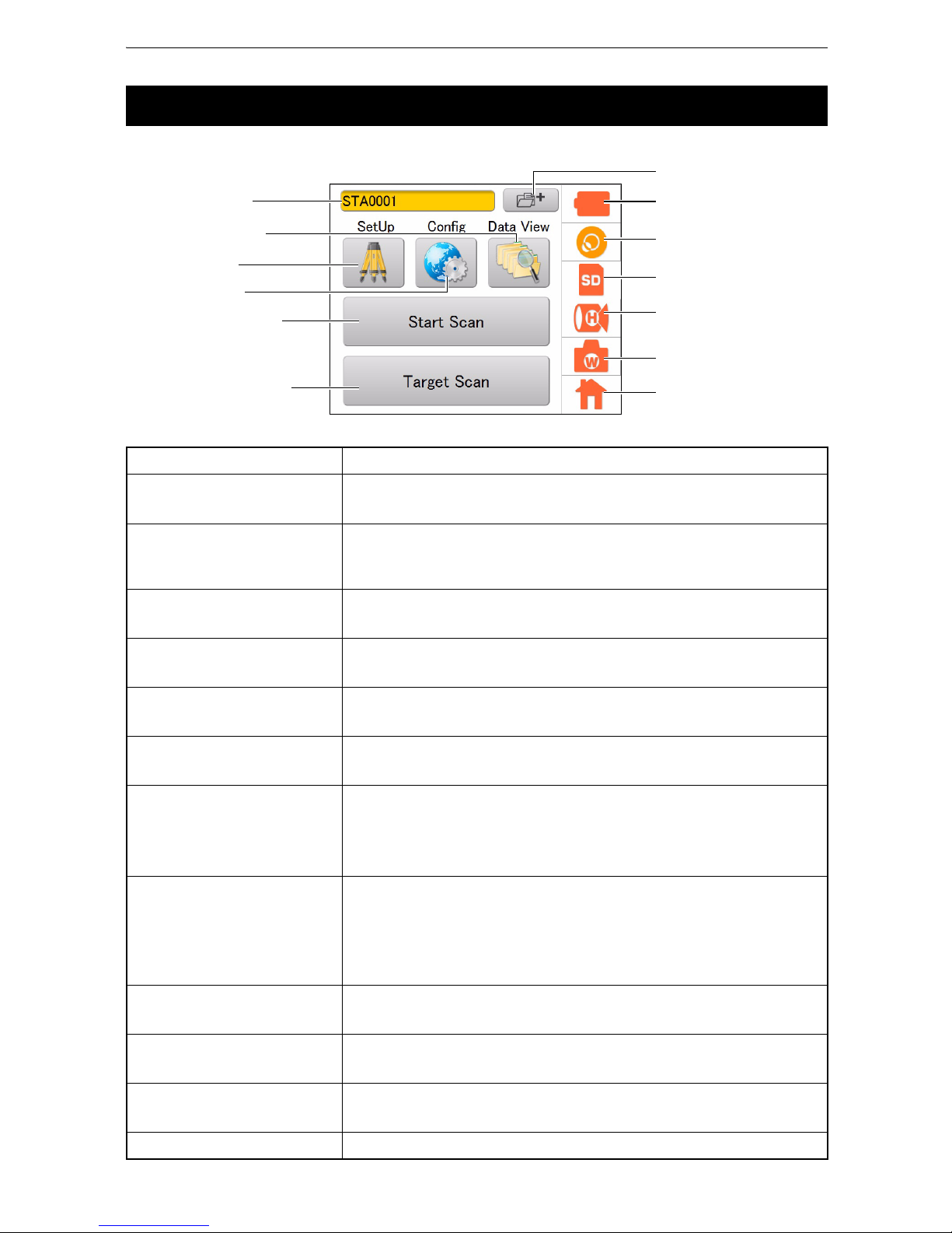
Icons for frequently used functions and various setting modes are displayed on the main menu.
4.3 Display and Functions of the Main Menu
Name of the button / icon Function(s)
Station Setting button
Sets a new station name.
“9. STATION SETTINGS”
SetUp icon
Enters the SetUp mode to set the occupied point name and the
backsight point name.
“9.2 Setting the Point Name (Occupied point and Backsight point)”
Config icon
Enters the Config mode to configure various settings.
“8. FLOW OF THE CONFIGURATION SCREEN”
Data View icon
Enters the Data View mode.
“8.10 Data structure in the SD card”
Start Scan button
Starts Scanning.
“10.2 3D Scanning”
Target Scan button
Scans the target.
“10.1 Target Scanning”
Battery icon
Displays the remaining battery life. Also, use it to replace the batteries
while scanning.
“6.6 Battery Power Remaining Display”
“6.7 Replacing the Batteries during the power is ON”
Tilt Setting icon
Displays the electronic circular level.
Switches the tilt, ON or OFF.
“7.1 Setting the Tilt Sensor ON/OFF”
Adjusts the tilt sensor installation error.
“11.2 Tilt Sensor Calibration”
SD Card icon
Displays the detail of the SD card usage.
“6.5 Using the SD Card”
Scan Setting icon
Sets the conditions of scanning.
“10.2 3D Scanning”
Camera Setting icon
Sets the built-in camera
“7.2 Camera Settings (Angle of view and Resolution)”
Home icon Displays the main menu.
Battery icon
Tilt Setting icon
SD Card icon
Scan Setting icon
Camera Setting icon
Home icon
Data View icon
Config icon
Start Scan button
Target Scan button
SetUp icon
Main Menu
Station Setting button
Station name
Page 16
12
4. PRODUCT OUTLINE
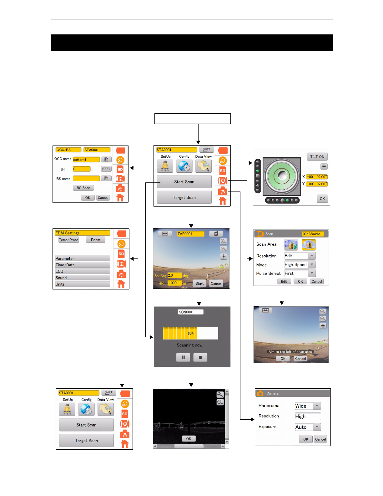
The following illustrates the main flow of the screens.
Use a stylus pen to operate the screen.
• Do not scratch or use any sharp objects other than a stylus pen on the screen face.
4.4 Flow of the Screens
Power ON
Main Menu
Scan Setting Screen
Camera Setting Screen
Config Screen
Tilt Setting Screen
SetUp Screen
Main Menu
Page 17
13
5. PREPARATIONS BEFORE USE
• The station information and the measured data are stored in the SD memory card. Make sure that the
SD memory card is inserted before measuring.
• When using a coordinate point that is already known, make sure that the data (coordinate point file
(CSV file), etc.) is stored in the SD card.
• Use an SD card with the speed at 6MB/sec or faster, or an SDHC card of Class 6 or higher. SD cards
of Class 4 or lower cannot be used.
• Use the supplied battery (BDC70) for the instrument.
• See “12. BATTERY CHARGING” on how to charge the batteries.
• Do not break the projection (Open/Close sensor) inside the battery cover. Be careful not to pinch your
finger.
• Make sure that no water drop or dust gets inside the instrument when setting or removing the batteries.
• When storing the batteries, remove the batteries from the instrument or the charger.
• The batteries are chemical products that use a chemical reaction and have a limited life expectancy.
Even if the batteries are not used, they deteriorate over time and the capacity decreases. If the service
lives of the properly charged batteries are shortened, purchase new ones, as the batteries have come
to the end of their useful service life.
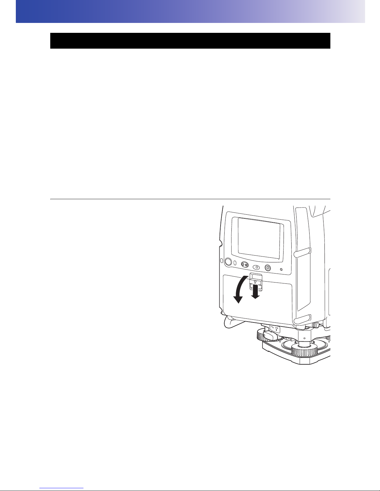
PROCEDURE
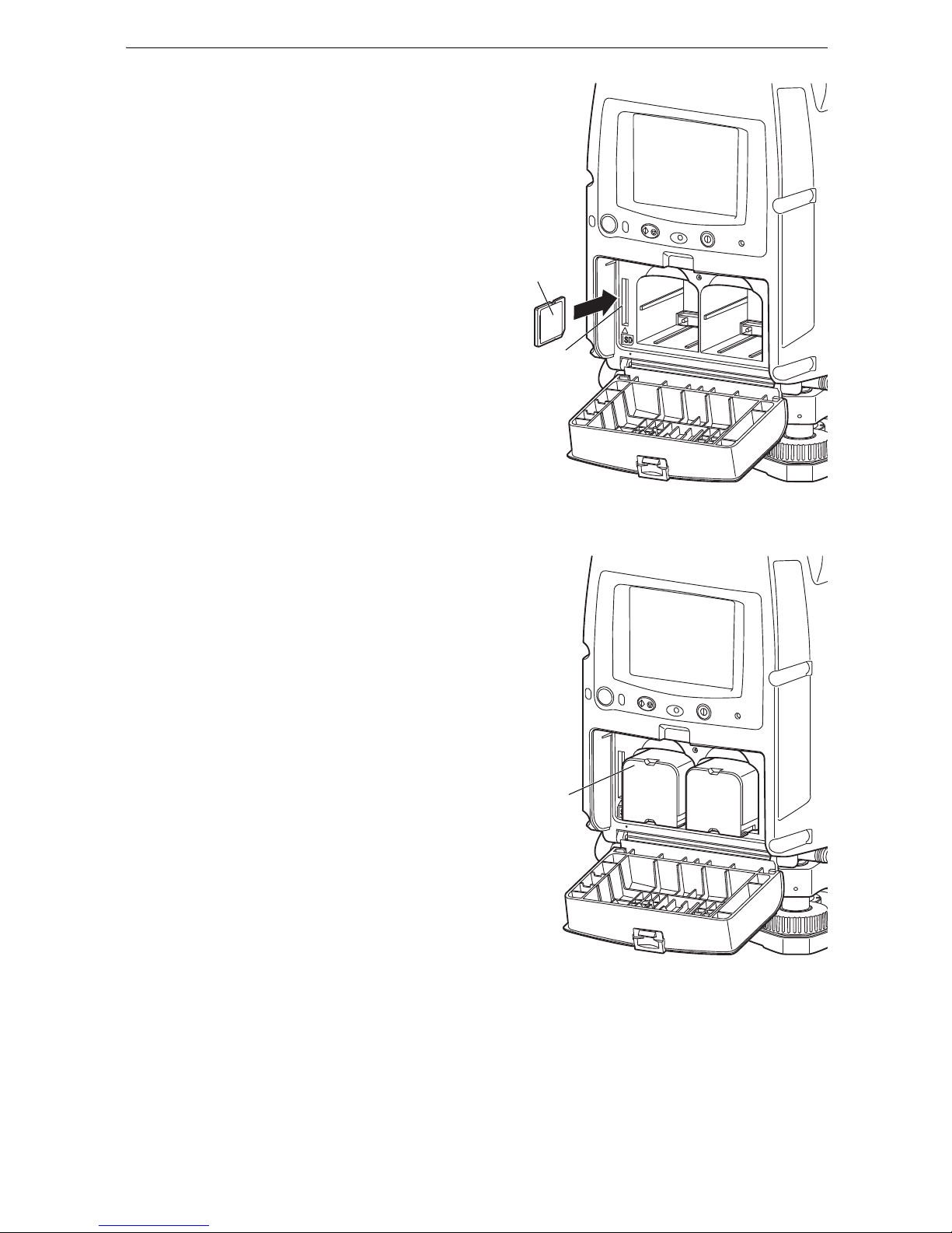
1. Slide down the lever on the battery cover (Right)
to open.
5.1 Inserting an SD memory card and Installing the Battery
Page 18
14
5. PREPARATIONS BEFORE USE
2. Insert a SD card to the card slot.
• Please make sure you have the front and back of
the SD card facing correctly when inserting into the
card slot.
• When removing the SD card, press the center of
the card slowly. Pressing the edge of the card may
cause the card to eject strongly.
• While a progress bar displays, do not remove the
SD card.
Otherwise, the data may be destroyed.
3. Checking the terminal side on the battery, insert
two batteries as shown.
4. Close the battery
cover (Right).
Make sure it clicks.
SD card
Card slot
Battery
Page 19
15
5. PREPARATIONS BEFORE USE
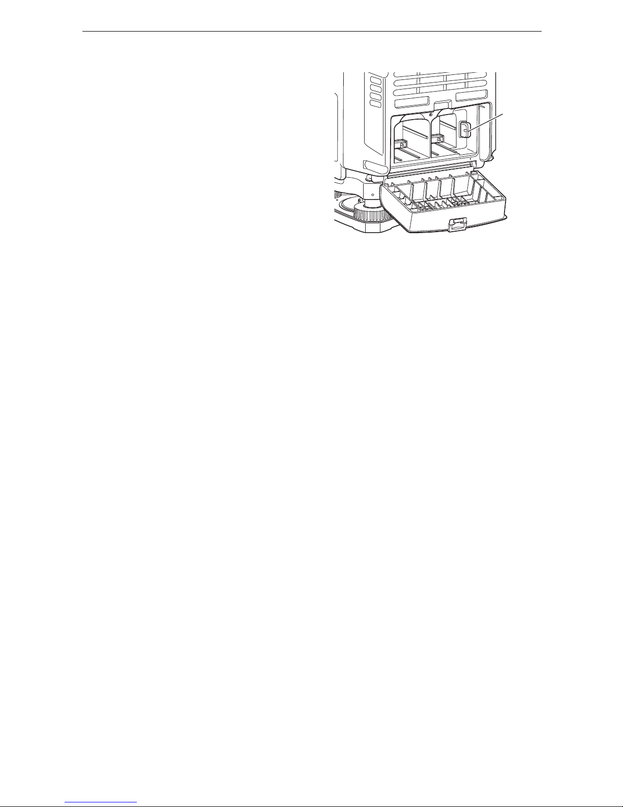
5. Open the battery cover (left).
6. Similarly, Install two batteries.
• Never remove the backup memory in the battery
cover (Left).
7. Close the battery cover (Left). A click is heard
when the cover is secure.
Backup
memory
Page 20
16
5. PREPARATIONS BEFORE USE
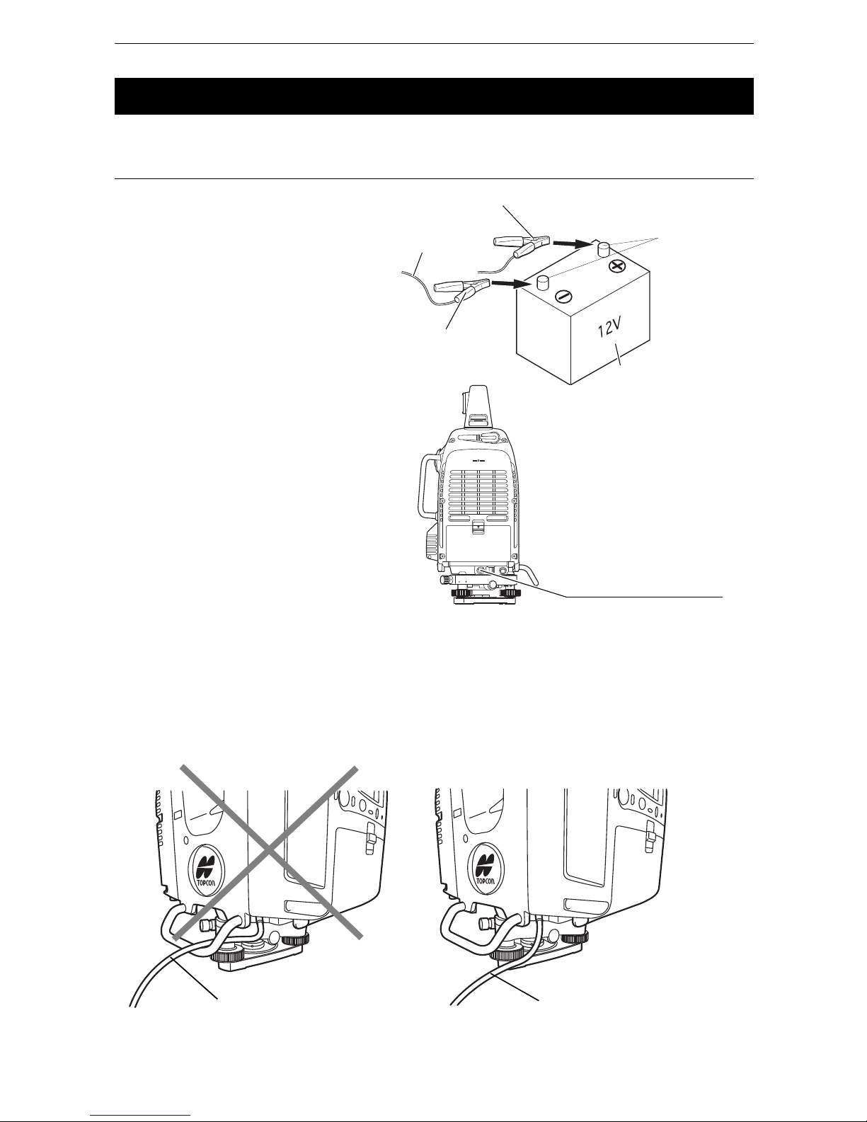
Use the external power source if necessary.
PROCEDURE Connect the external power source
1. Connect the clip of the external
power cable PC-26 (Sold separately)
to a terminal of commercial external
power source.
2. Connect the external power cable
PC-26 to the power source
connector.
• The GLS-2000 automatically starts by connecting the external power source without the batteries
(BDC70) in the instrument.
• Make sure to close the connector cap of the power source connector when an external power source
is not being used.
• When connecting the power cable to the power source connector, place the power cable outside the
side handle as shown below. If the power cable is inside the side handle, it may be disconnected due
to the instrument’s rotation. Rotate the instrument before turning the power on to make sure that it does
not hit the power cable.
5.2 Connecting the External Power Source
PC-26
Red clip (+)
Black clip (-)
External power source
Terminal
Power source connector
Power cable is inside the
side handle.
Power cable is outside the
side handle.
Page 21

17
5. PREPARATIONS BEFORE USE
The following describes the overview of scanning procedure:
5.3 Overview of Scanning Procedure
Scan
Set the station, the occupied point and the backsight point
1. Scan the target.
2. Perform a 3D scanning.
1. Set the station.
2. Turn the power ON.
1. Install the instrument.
Prepare for scanning
Turn the power OFF
“6.4 Setting Up the Instrument”
“6.3 Power ON/OFF”
“9.1 Creating a New Station”
“9.2 Setting the Point Name (Occupied point and Backsight point)”
“10. MEASURING (SCANNING)”
“10.1 Target Scanning”
“10.2 3D Scanning”
2. Set the occupied point name and the backsight point name, and then scan
the backsight point.
3. Set up this instrument.
“7. INSTRUMENT SETTINGS”
1. Turn the power OFF.
“6.3 Power ON/OFF”
“8.9 Handling the Coordinate Point File”
Page 22
18
6. PREPARATION FOR MEASUREMENT
The carrying handle can be removed from the instrument. To remove it, loosen the 2 handle rocking
screws.
• Remove the handle when scanning around the zenith or the whole circumference.
• To remove the handle, hold both sides of the handle and lift it straight above. If you hold the handle by
one hand or incline it, the terminal attached on the handle may be damaged.
• When using the instrument with the handle detached, pay careful attention that no water or dust has
adhered to the terminal.
To attach the handle, position and align the handle and then tighten up the handle locking screws. (Two
points need to be screwed.)
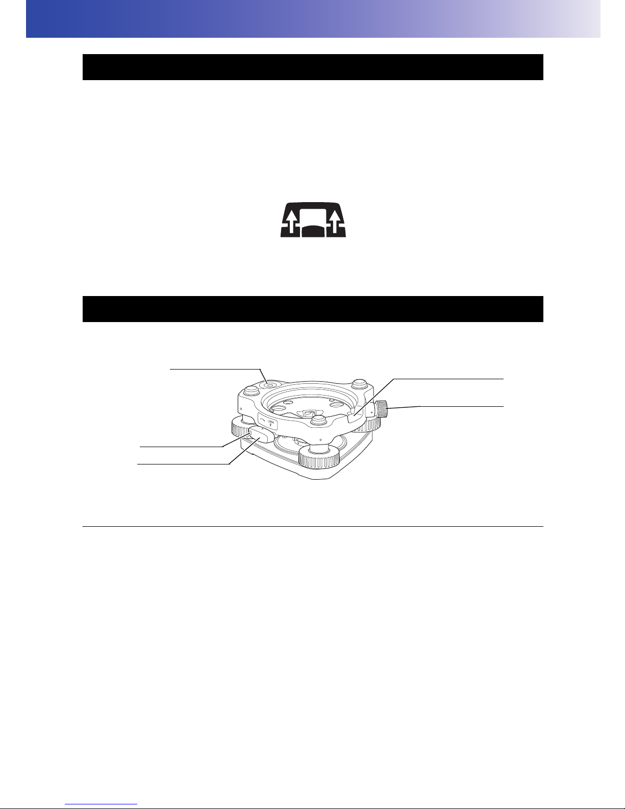
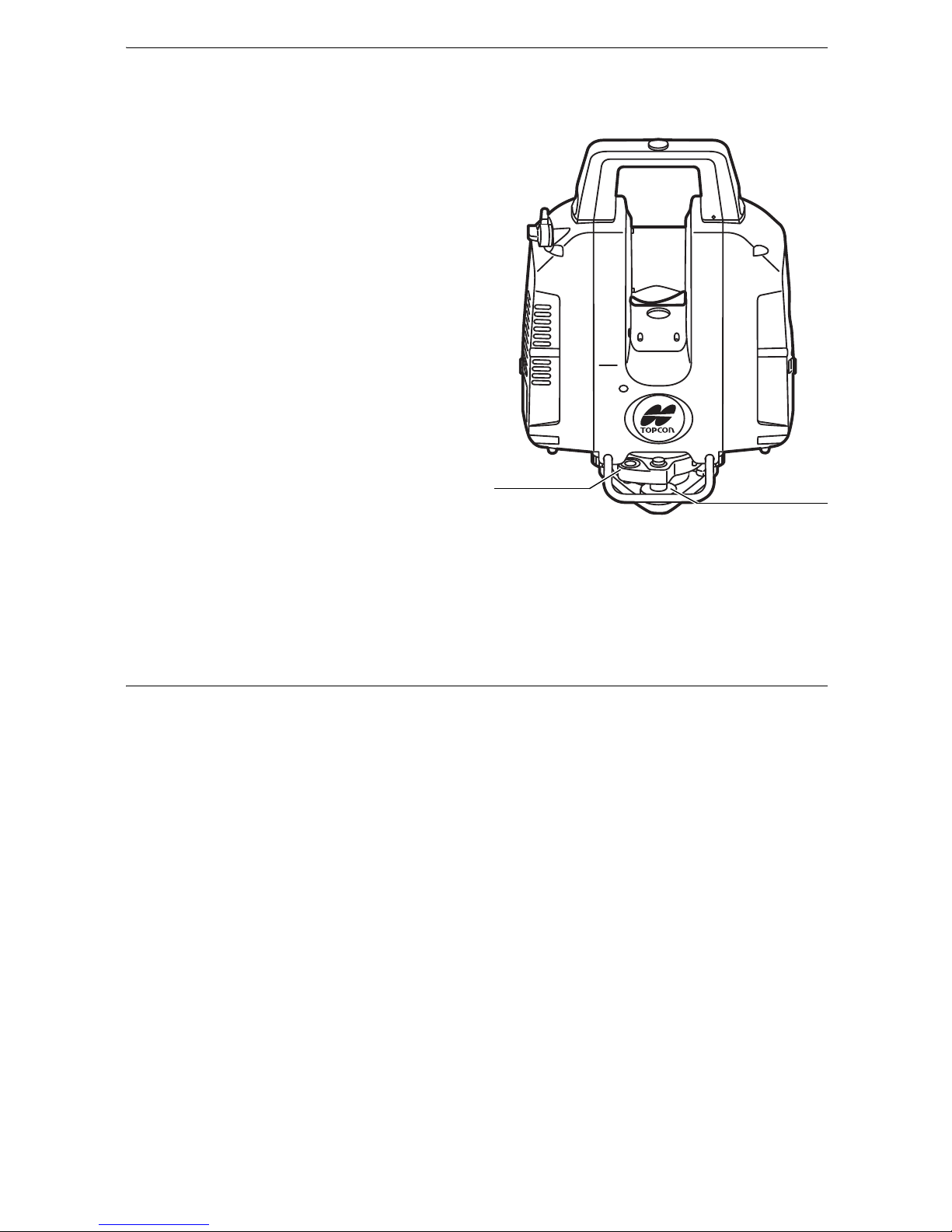
The instrument is easily detached or attached to the tribrach.
PROCEDURE Detaching the instrument from the levelling base
1. Loosen the levelling base locking screw by
turning 2 or 3 rotations in the counterclockwise
direction.
2. Turn the tribrach clamp counterclockwise to
loosen. (When the tribrach fixing lever securing
screws are screwed in, use the driver provided in
the package to loosen.)
3. Lift the instrument to detach.
6.1 Detaching / attaching the Handle
6.2 Detaching / attaching the Tribrach
Securing screw
Tribrach fixing lever
Tribrach alignment groove
Tribrach fixing screw
Tribrach circular level
Page 23
19
6. PREPARATION FOR MEASUREMENT
PROCEDURE Attaching the instrument to the levelling base
1. Check that the tribrach fixing screw has been
loosened.
2. Align the alignment piece and the tribrach
alignment groove and lower the instrument onto
the levelling base.
3. Turn the tribrach fixing lever clockwise to tighten.
4. Turn the tribrach fixing screw clockwise to
tighten.
• Locking the tribrach fixing lever
The tribrach fixing lever can be locked from being moved accidentally. This is useful if the upper
instrument section is not being detached very often. Simply tighten the securing screw on the fixing
lever with the accessory screw driver.
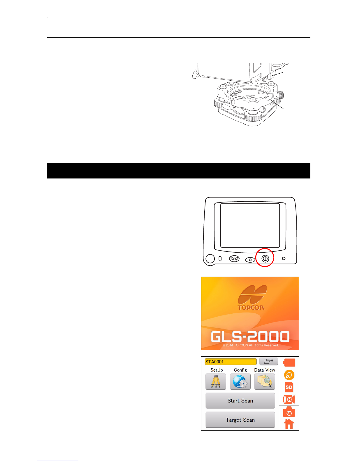
PROCEDURE Power ON
1. Press the power key located on the right side of
the instrument.
After the power Indicator turned on, a startup
screen will be displayed.
• It takes approximately 3 minutes after the power
has been switched ON to initialize the instrument
and warm up the laser.
Do not turn the instrument with your hands or
operate any keys while the instrument is turning.
The main menu will appear.
• If [TILT OVER] is displayed, this instrument is
inclining beyond the tilt angle compensation
range. Level this instrument using the tilt sensor.
“6.4 Setting Up the Instrument”
6.3 Power ON/OFF
Alignment
piece
Tribrach
alignment
groove
Main menu
Page 24
20
6. PREPARATION FOR MEASUREMENT
• Internal Calibration
In order to maintain its precision, the instrument will automatically perform internal calibration. The
internal calibration will take approximately 2 minutes.
Confirm that, after the setup is finished, the
positional relationship between the instrument
and the tribrach will be as shown in the figure
here.
• Do not turn the head or the scanner unit with your
hands while the power is ON. If it has been turned
by force, turn the power ON again. (Except when
collimating)
PROCEDURE Power OFF
1. Press and hold (about 2 seconds) the power key
located on the right side of the instrument.
The power is switched off.
Leveling screw
Circular level
Page 25
21
6. PREPARATION FOR MEASUREMENT
• Level and center the instrument precisely. Level and center the instrument precisely to insure the best
performance.
• Use tripods with a tripod screw of 5/8 in. diameter and 11 threads per inch, such as the Type E TOPCON
wide-frame wooden tripod. Do not use a metallic tripod.
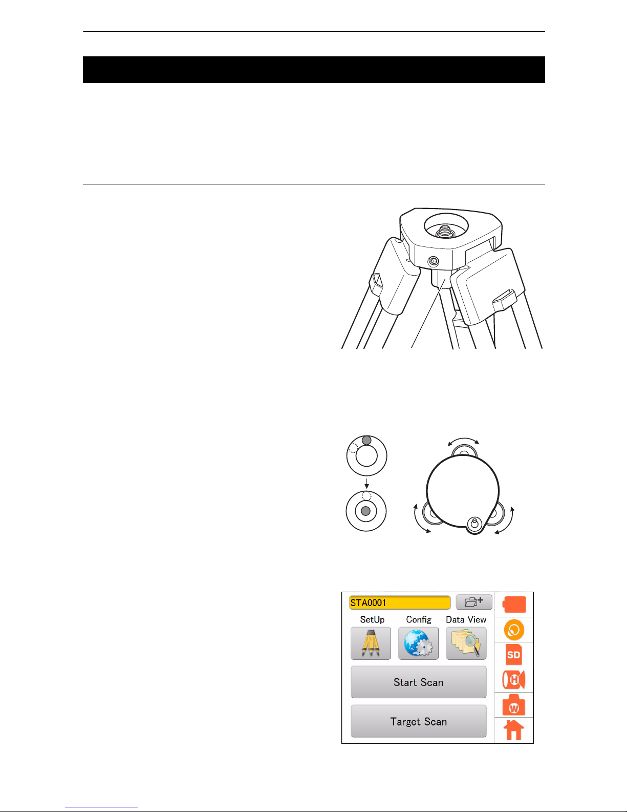
PROCEDURE Leveling and Centering the Instrument
1. Setting up the Tripod
First, extend the extension legs to suitable
lengths and tighten the screws on their
midsections.
2. Place the instrument on the tripod head.
Place the instrument on the tripod head, lightly
tighten the centering screw.
Slide the instrument by loosening the centering
screw, place the point over the survey point, and
then tighten the centering screw.
3. Roughly Leveling the Tribrach by Using the
Tribrach circular level
Turn the leveling screws A and B and adjust the
bubble to stay at the top or bottom of the circular
level.
Turn the leveling screw C to bring the bubble to
the center of the tribrach circular level.
4. Centering with the Laser Plummet
Turn the power of this instrument ON.
Press the Tilt Setting icon.
6.4 Setting Up the Instrument
Centering screw
Leveling screw A
Leveling screw B
Leveling screw C
Tribrach circular level
Page 26
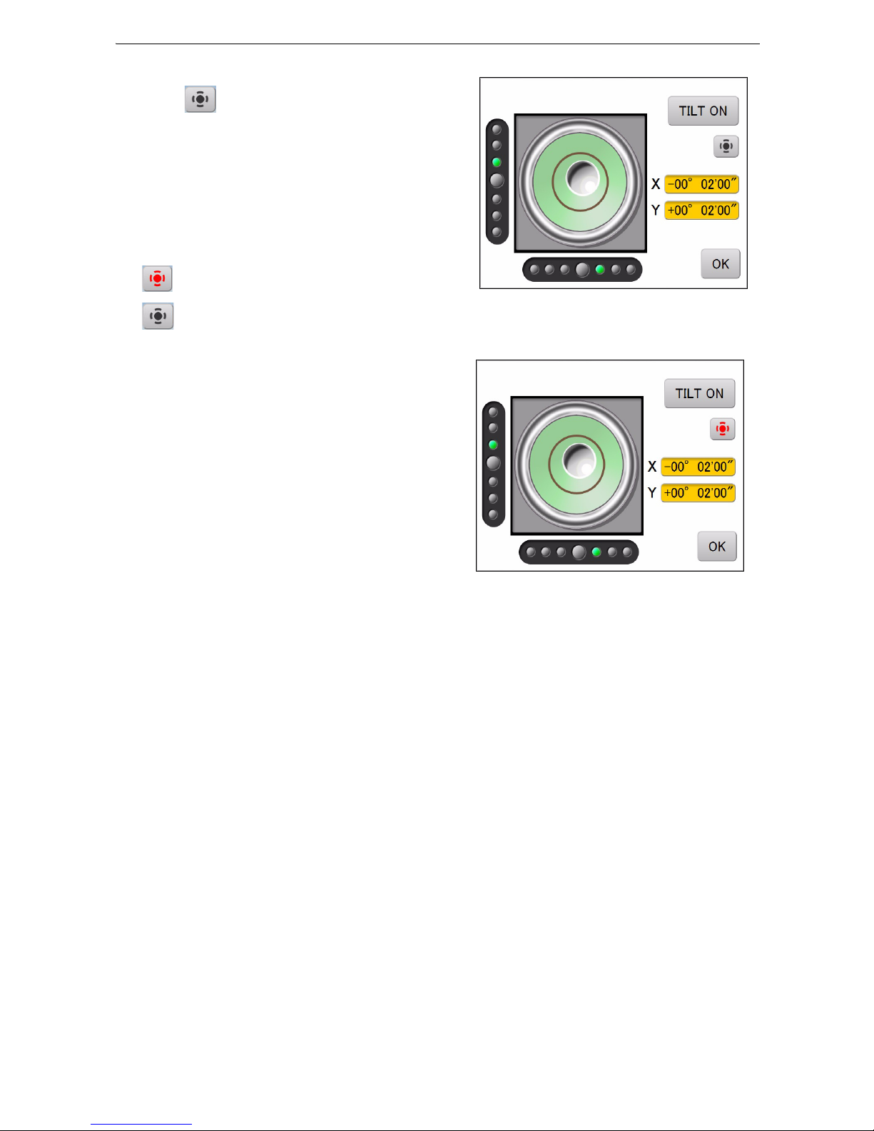
22
6. PREPARATION FOR MEASUREMENT
The electronic circular level is displayed.
Press , and then the laser plummet beam
will
be emitted from the bottom of the instrument.
“” indicates the bubble in circular level.
The line within the electronic circular level is set
at ±6'. The amount of dislocation will not be
displayed when the bubble is beyond the line.
Center “” in the circular level using foot screws.
Slide the instrument by loosening the centering
screw, place the point on the survey point, and
then tighten the centering screw.
Try to keep the instrument from rotating when
sliding it so as to minimize the dislocation of the
bubble.
Repeat step 3 and 4 if necessary.
5. Press [OK] after centering.
: Laser plummet beam is lit.
: Laser plummet beam is off.
Page 27
23
6. PREPARATION FOR MEASUREMENT
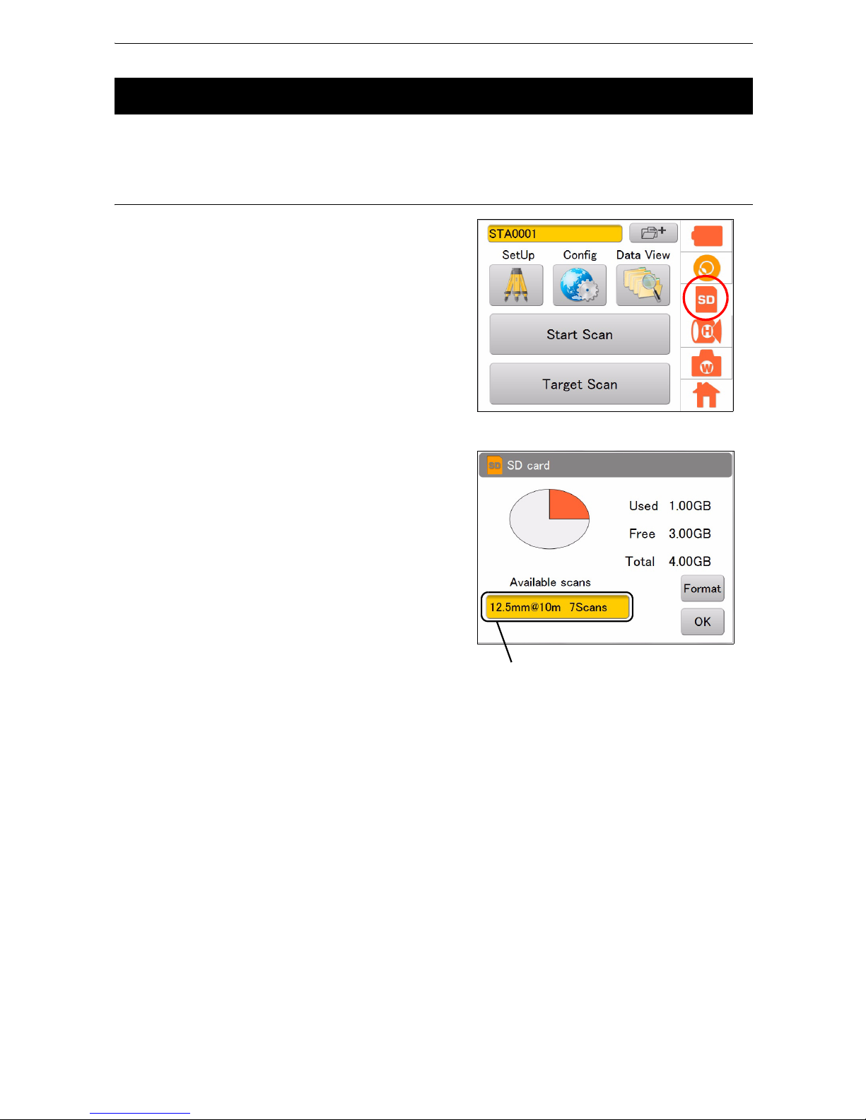
Tap the SD Card icon to check the detail of the SD card usage.
PROCEDURE
1. Press the SD Card icon.
The confirmation window will appear.
Press [Format] to format the SD card.
Press [OK] in the confirmation message window
to start the format.
The time required to format an SD card depends
on the volume of the SD card.
2. Press [OK] to return to the main menu.
• Note that when the card is formatted, all files in the card are deleted and cannot be used.
6.5 Using the SD Card
It means that there are seven scans worth of
memory available when the scanning is to be
done within the set scanning range at a
resolution of 12.5mm@10m.
Page 28
24
6. PREPARATION FOR MEASUREMENT
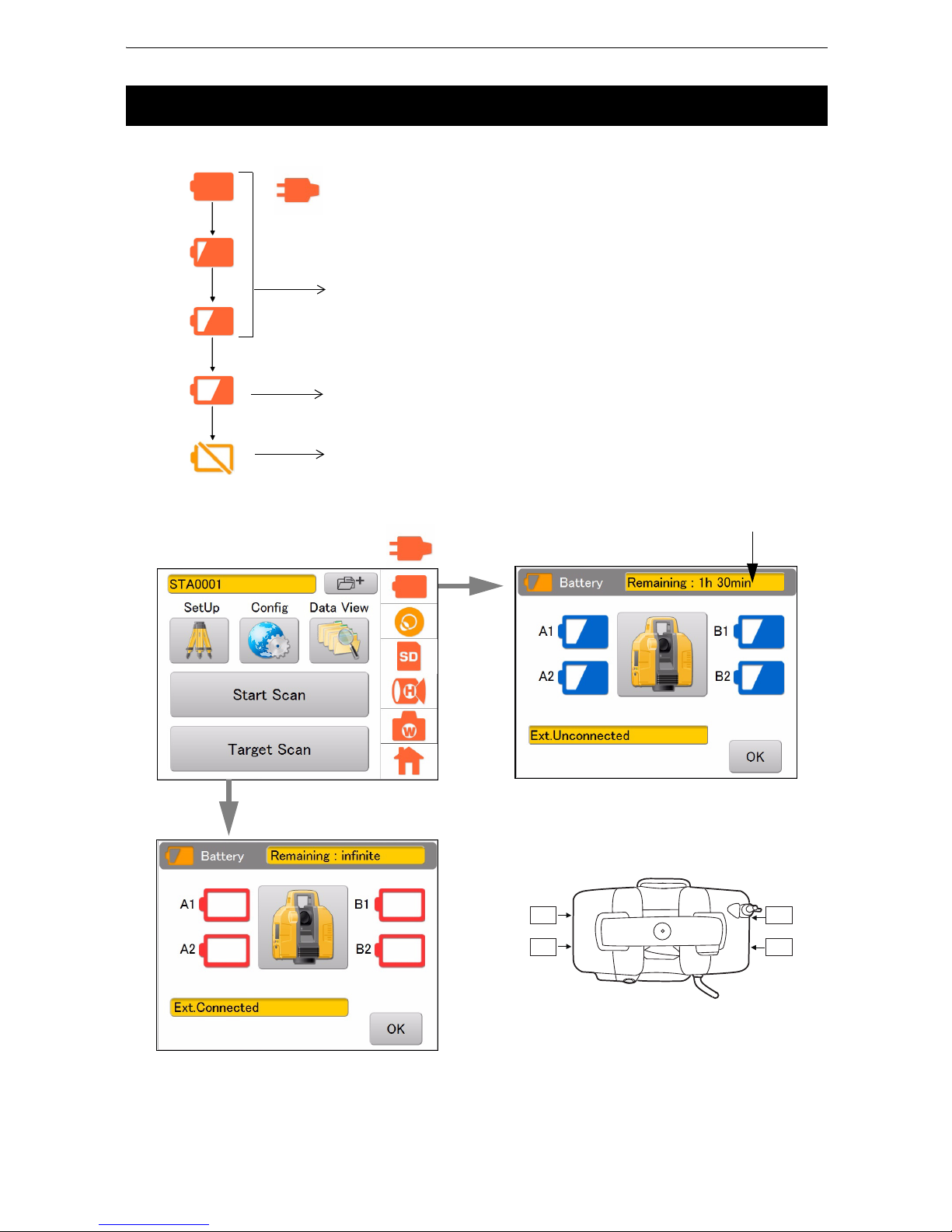
Battery power remaining display indicates the power condition.
Press the Battery icon to display the remaining battery time.
• The battery operating time will vary depending on the environmental conditions such as ambient
temperature, charging time, the number of times of charging and discharging etc. It is recommended for
safety to charge the battery beforehand or to prepare spare full charged batteries.
“12. BATTERY CHARGING”
6.6 Battery Power Remaining Display
Measurement is possible.
The power is poor. Please replace with fully
charged batteries.
Measurement is impossible.
Please replace with fully charged batteries.
( : When using external power source)
• The remaining battery level will not be displayed when an external
power source is used.
B1A1
A2
B2
Remaining battery time
Position of each battery
(Top View)
( : When using external power source)
When using external power source
Page 29
25
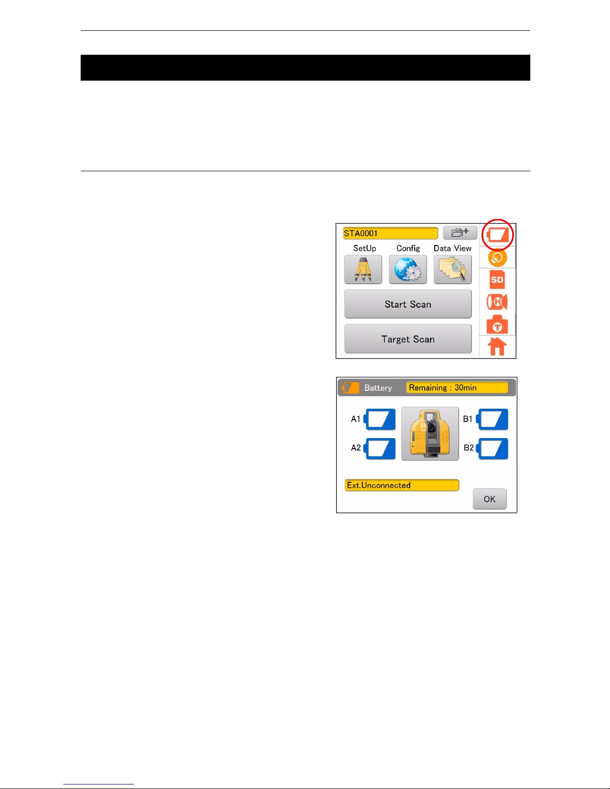
6. PREPARATION FOR MEASUREMENT
• When replacing the built-in batteries, replace all four batteries with fully charged batteries.
• Replace two batteries at a time: Replace A1 and A2 batteries first, and then B1 and B2 batteries, all with
fully charged ones.
“ Position of each battery” on page 24
PROCEDURE
If the battery power becomes low during the power is ON, replace the batteries by following the instruction
below to continue the scanning:
1. Press the Battery icon.
The remaining battery level will be displayed.
2. Open the right-side battery cover to replace two
batteries.
3. Close the right-side battery cover.
Confirm that both A1 and A2 batteries are
recognized and that the battery level has
increased.
4. Similarly, open the left-side battery cover to
replace two batteries.
5. Close the left-side battery cover.
Confirm that both B1 and B2 batteries are
recognized and that the battery level has
increased.
6. Press [OK].
6.7 Replacing the Batteries during the power is ON
Page 30

26
6. PREPARATION FOR MEASUREMENT
Numerical, uppercase, and lowercase alphabetic characters can be entered when entering a station, an
instrument height, or a backpoint.
The function of a keyboard is as follows.
Characters that can be entered
6.8 Entering Numeric and Alphabetic Characters
Items to enter characters Characters that can be entered Number of characters
• Target name
• Station name
• Occupied point name
• Backsight point name
• Alphabet : a to z, A to Z
• Numeric characters: 0 to 9
• Symbols (“*”, “:“, “/“, “?“ are disabled)
8 characters or less
When entering
capital letters
When entering
lower case letters
When entering
alphabetic characters
When entering
numeric characters
or symbols
Deletes the letter on the left side
switch
Inputted characters
Cancel the input data
Determines the selection
Page 31

27
6. PREPARATION FOR MEASUREMENT
Use the target or (single) prism when performing “target scanning”.
• Be sure to use the target sheets for the GLS-2000/1500 manufactured by TOPCON.
• Select the target sheet (large, medium, small) based on the distance to the object being scanned.
(Target sheet (large / medium) is sold separately)
Assembling the target
• Refer to the instruction manual of the prism in use for its assembling.
PROCEDURE
1. Attach the alignment piece of the prism adaptor
(sold separately) to the tribrach (sold separately),
according to the position shown in the figure
here.
2. Tighten the tribrach fixing lever firmly by turning
clockwise.
6.9 Preparing the Target
Distance to the
scanning target (m)
Target sheet Size (m)
50-200 Large 0.12
10-100 Middle 0.06
2-50 Small 0.03
Prism-adapter
Alignment piece
Tribrach
Tribrach fixing lever
Page 32

28
6. PREPARATION FOR MEASUREMENT
3. Install the target board (Sold separately) as
shown in the illustration.
Tighten the settlement screw surely.
4. Put the magnetic target sheet on the target
board. At this point, adjust the center marks (4)
of the target sheet and the target board exactly.
Settlement
screw
Center mark
Target board
Target sheet
Center mark
Page 33

29
7. INSTRUMENT SETTINGS
Settings for this instrument are set through main menu icons and settings mode (“8. FLOW OF THE
CONFIGURATION SCREEN”).
When the auto tilt correction function for the vertical and horizontal angles is turned ON, the 2-axis tilt
sensor is activated, automatically compensating errors in vertical and horizontal angles due to inclination
of the standing axis.
To ensure precise measurement, set the auto tilt correction [Tilt] to ON. If the error is out of the automatic
compensation range, [TILT OVER] will be displayed. In such a case, level this instrument. The screen
appearing before [TILT OVER] was displayed will appear again when the tilt enters the automatic
compensation range after the leveling.
• This instrument automatically compensates errors in the vertical and horizontal angles by detecting the
inclination of the standing axis of the instrument towards the X, Y directions.
• Indication of the inclination of the X, Y directions may not be consistent when this instrument is mounted
on an unstable stand or when the wind is strong. In such a case, stop the auto tilt correction for the
vertical and horizontal angles to operate.
PROCEDURE Setting example: Tilt ON to OFF
1. Press the Tilt Setting icon.
7.1 Setting the Tilt Sensor ON/OFF
Verticality
Standing axis
Inclination of the
standing axis towards X
direction
Verticality
Inclination of the standing
axis towards Y direction
Trunnion axis
Horizontal
Standing axis
Page 34

30
7. INSTRUMENT SETTINGS
2. Press [TILT ON.]
The tilt is set to OFF.
The line within the electronic circular level is set
at ±6'. The amount of dislocation will not be
displayed when the bubble is beyond the line.
3. Press [OK.]
The Tilt Setting icon is switched OFF ( ).
: OK (It is correctable by using the tilt
correction function.)
: NG (It is not correctable by using the
correction function.)
: OFF (The tilt correction function is turned
off.)
Page 35

31
7. INSTRUMENT SETTINGS
The built-in camera automatically takes photographs of the entire scanning range and saves the
photograph data in the image file when scanning. (when selecting “Wide” or “Tele”)
The photograph data of the entire scanning range consists of several photographs. As the scanning area
becomes wider, the number of photographs taken will increase.
Also, as the resolution becomes finer, the file size will increase. Set the resolution as needed.
1. Press the Camera Setting icon.
• The Camera Setting icon displayed in the status
screen shows the selective condition of the
Panorama selected.
2. Select “Panorama,” “Resolution,” “Exposure,”
and press [OK.]
Setting items and each selection
(*: Factory default)
(1) Panorama: Wide* / Tele / OFF
• Remove the Wide-angle camera lens cap of the instrument when selecting “Wide".
(2) Resolution: Low / Normal / High*
(When selecting “Wide” for the “Panorama” camera setting: “High”
only)
(3) Exposure: Auto* / Manual
7.2 Camera Settings (Angle of view and Resolution)
Panorama Angle of view
Wide
Diagonal 170°
Te le
8.9° (V) × 11.9° (H)
OFF
No image data
Resolution Number of pixels
Low
480 (V) × 640 (H)
Normal
960 (V) × 1280 (H)
High
1920 (V) × 2560 (H)
Exposure Exposure value
Auto
The exposure value will be automatically determined by the signal level of
the center of the scanning range.
Manual
The exposure value can be adjusted on the exposure adjust screen at the
start of the scanning.
: Wide
: Tele
: OFF
Page 36

32
7. INSTRUMENT SETTINGS
By changing the scanning settings, measurement that suits the purpose can be carried out.
Resolution can be selected from the predetermined resolutions or by entering the desired resolution.
1. Press the Scan Setting icon.
• The Scan Setting icon displayed in the status screen
shows the selective condition of the range mode.
2. Select “Scan Area,” “Resolution,” “Mode,”
“Pulse Select,” and press [OK.]
(1) Scanning range
Range setting scanning or Whole circumference scanning can be selected.
“Scanning range” on page 64
(2) Resolution (a predetermined value)
Select a predetermined resolution listed below:
50mm@10m, 25mm@10m, 12.5mm@10m, 6.3mm@10m, 3.1mm@10m, Edit
“50mm@10 m” means “a measurement accuracy of 50mm in pitch at a position of 10 m ahead”.
For the range of measurement distance and the accuracy of measurement, see the following table.
*1) Range varies depending on weather conditions or stability of the atmosphere.
7.3 Settings for Scanning Conditions
Range of
measurement *1)
Reflectivity
Range mode
Detail
High
Speed
Low
Power
Standard
Close
9% reflection----40m
18% reflection 40m 90m 90m 150m -
90% reflection 100m 210m 210m 350m -
: Detail
: High Speed
: Low Power
: Standard
: Close
Range mode
Pulse Select
Resolution
(a predetermined value)
Scanning range
Resolution
(a desired value)
Estimated time for scanning
Page 37

33
7. INSTRUMENT SETTINGS
(3) Resolution (a desired value)
The horizontal and vertical start point angle, end point angle and measurement pitch can be set to
a desired value. (Set the start point angle and end point angle in the scan range setting screen
(
P. 65).)
Setting the measurement pitch
Enter the vertical or horizontal measurement pitch settings within the scanning range by using one
of the following three methods. Each value is linked.
mm : Enter the pitch between scanning points
pts : Enter the total number of scanning points
deg : Enter the angle between scanning points
When entering the space between the two measurement points in millimeters, enter or measure
the distance to the target beforehand.
About the angle of the starting point and the end point
The angle which is set within the scanning range will be displayed.
The angle will be H : -180~0, V : -135~-45 when whole circumference scanning is to be done.
Unit of measurement pitch:
mm/deg/pts
Start point angle
End point angle
Measurement pitch
Horizontal
Vertical
Distance measurement
Select “Edit”
Press [Edit]
“7.4 Measuring
Distance to the Target
Measurement Object”
Page 38

34
7. INSTRUMENT SETTINGS
(4) Range mode
Range mode settings are as follows.
Detail / High Speed / Low Power / Standard / Close
Please refer to the following for details.
The number of measured data may vary depending on the measurement distance or the selected
range mode in the circumstances noted below.
• In the case where the incident angle of the distance measurement laser toward the target
measurement object was narrow.
• In the case where the target was measured by using objects that have a multiple reflection effect
such as a mirror.
• In the case where a highly reflective object located close and facing toward the instrument is
measured.
(5) Pulse select
When the target measurement objects are in the foreground and background as shown below, the
distance of either object can be measured by changing the pulse selection.
• Depending on the reflection ratio of or the distance between the target measurement objects, it
might not be possible to measure the target even by switching from first to last or vice versa.
Range mode Cycle of light emission Laser class Distance
Detail 120 KHz Laser class 3R Up to 100 m
High Speed 120 KHz Laser class 3R Up to 210 m
Low Power 48 KHz Laser class 1M Up to 210 m
Standard 60 KHz Laser class 3R Up to 350 m
Close 120KHz Laser class 3R Up to 40 m
Pulse Select : First
Pulse Select : Last
Target measurement
object (foreground)
Target measurement
object (background)
GLS-2000
Top View
Distance finder laser
Page 39

35
7. INSTRUMENT SETTINGS
An overall distance to the target measurement object that is required when setting the resolution (a
desired value) of the scanning parameter in millimeters will be measured as indicated below. (The
distance is not required when using the unit of points or degrees.)
PROCEDURE
1. Press the Scan Setting icon.
2. Select “Edit” in “Resolution”, and then press
[Edit].
3. Press .
7.4 Measuring Distance to the Target Measurement Object
Page 40

36
7. INSTRUMENT SETTINGS
4. Press to switch the camera to "Tele"
and tap the target measurement object.
“Explanation of the buttons” on page 61
The instrument will automatically turn to the
target measurement object which will be
displayed around the middle of the screen.
While doing this, the horizontally rotating part
and the turn of the scanner unit will be locked.
To unlock, turn the horizontally rotating part or
the scanner unit manually.
5. Press [Meas].
6. The scanning distance is displayed. (20.1m)
Press [OK].
• This function confirms rough distance and is not for measuring accurate distance to the target.
• Do not use a prism or a target sheet in this measurement.
Page 41

37
8. FLOW OF THE CONFIGURATION SCREEN
Press the Config icon to enter the Config mode.
The following illustrates the flow of the configuration screen.
[Parameter]
[Temp / Press]
[Prism]
[Tilt 0 Set]
[PC offset]
[PL offset]
Press the Config icon.
[EDM Settings]
Page 42

38
8. FLOW OF THE CONFIGURATION SCREEN
[Back Light]
[LCD ]
[Sound]
[Units]
[Unit]
[Coord]
[Sound]
[Time / Date]
[Calib Date]
[Time / Date]
Page 43

39
8. FLOW OF THE CONFIGURATION SCREEN
To compensate the measured data, enter the temperature and atmospheric pressure during the
measurement.
PROCEDURE
1. Press the Config icon.
2. Press [EDM Settings].
3. Press [Temp/Press].
4. Enter the temperature and atmospheric
pressure, and then press [OK].
Temperature:
-10 °C to + 50 °C (increments of 0.1 °C)
(Default setting: +20 °C)
Atmospheric pressure:
560 hPa to 1066.0 hPa (increments of 0.1 hPa)
(Default setting: 1013.0 hPa)
8.1 Setting Temperature and Atmospheric Pressure
Page 44

40
8. FLOW OF THE CONFIGURATION SCREEN
Set the prism constant to be used and the flash light.
PROCEDURE
1. Press the Config icon.
2. Press [EDM Settings].
3. Press [Prism].
4. Enter the prism constant, choose ON/OFF of
the flash light, and then press [OK].
When the target scanning is started after the
flash light is set to “ON” and the instrument is set
to use the prism, a white spot beam will be
emitted from the scanner unit to detect the
position of the prism.
Prism Constant : -99 mm to
+
99 mm
(Default setting: 0 mm)
Flashlight : ON/OFF
(Default setting: OFF)
8.2 Setting the Prism Constant and Flash Light
Page 45

41
8. FLOW OF THE CONFIGURATION SCREEN
Set the date and time to record the date in the measurement data.
[Setting example] Date: July 11, 2014 Time: 12:00
PROCEDURE
1. Press the Config icon.
2. Press [Time/Date].
3. Press [Time/Date].
4. Tap the value that you want to change, and use
the up and down arrows to set the date and
time, and press [OK].
8.3 Setting the Date and Time
Page 46

42
8. FLOW OF THE CONFIGURATION SCREEN
The date of the last calibration (precision calibration of measurement distance and angle) can be
displayed.
We recommend performing the precision calibration again within one year from the last calibration date.
PROCEDURE
1. Press the Config icon.
2. Select [Time/Date].
3. Select [Calib Date].
4. Press [OK].
The last calibration date will be displayed.
8.4 Displaying the Last Calibration Date
Page 47

43
8. FLOW OF THE CONFIGURATION SCREEN
Use the backlight if it is hard to look at the display section in the evening or in a tunnel.
The level of backlight brightness can be adjusted from OFF to 10.
PROCEDURE
1. Press the Config icon.
2. Press [LCD].
3. Press [Back Light].
4. Adjust the brightness using the slider, and then
press [OK].
8.5 Adjusting the Brightness of the Display Section
Page 48

44
8. FLOW OF THE CONFIGURATION SCREEN
The volume of the sound which can be heard from this instrument can be adjusted as follows.
PROCEDURE
1. Press the Config icon.
2. Press [Sound].
3. Press [Sound].
4. Adjust the volume with a slider, and then press
[OK].
8.6 Setting the Volume
Page 49

45
8. FLOW OF THE CONFIGURATION SCREEN
Select the units as follows.
PROCEDURE
1. Press the Config icon.
2. Press [Units].
3. Press [Unit].
4. Select the units for “Temperature,” “Pressure,”
“Distance,” and “Angle.”
Items set and options (* : Factory setting)
Temperature:
celsius* / fahrenheit
Pressure : hPa* / mmHg / inHg
Distance :
m* / ft (us) / ft (NT)
Angle :
deg* / gon
8.7 Selecting the Unit
Page 50

46
8. FLOW OF THE CONFIGURATION SCREEN
Select the coordinate system (ENH or NEH) as follows.
PROCEDURE
1. Press the Config icon.
2. Press [Units].
3. Press [Coord].
4. Select the coordinate system (ENH* or NEH),
and then press [OK].
* Factory setting
8.8 Selecting the Coordinate System
Page 51

47
8. FLOW OF THE CONFIGURATION SCREEN
Import the coordinate point file
The coordinate point name and the coordinate value described in CSV file format can be imported into the
instrument via the SD card. The occupied point name and the occupied point coordinate or the backsight
point name and the backsight point coordinate can be selected from the imported coordinate list.
The imported coordinate list is retained even after turning OFF the instrument.
Conditions to create the CSV file (coordinate point file)
Create the CSV file in accordance with the following conditions.
Example of creating a CSV file
1. Enter the name of the coordinate point and E, N, and H (X, Y, and Z) in a text file.
2. Change the extension to CSV or enter the name of the coordinate point and E, N, and H
(X, Y, and Z) in a file such as Microsoft Excel's.
3. Change the format of the file to CSV when saving it.
8.9 Handling the Coordinate Point File
Items Conditions for creation
CSV file
A CSV file is comma delimited, and records fields in the following order:
coordinate point name, E, N, H (X, Y, Z).
Example
pt-01,1105.494,1069.231,6.6,
pt-02,1110.989,1088.461,7.2,
pt-03,1116.483,1107.691,7.8,
Save the CSV file in the highest hierarchy in the SD card. If the file is saved in
any lower hierarchy, it cannot be imported.
Up to 250 coordinate points can be imported. (Up to 250 coordinate points are
registered.)
They are read with the coordinate system.
Always use “***.csv” for the file extension. (Case insensitive)
Point name
Use up to eight characters for the coordinate point name. (For a long string, up
to eight characters are automatically imported, and the ninth and subsequent
characters cannot be imported. As a consequence, multiple identical coordinate
point names may exist.)
Coordinate
value
Express the coordinate value within the range of ±99999999.999 m.
(A coordinate value that exceeds the range cannot be imported.)
Page 52

48
8. FLOW OF THE CONFIGURATION SCREEN
PROCEDURE How to import a CSV file (coordinate file) in the SD card
1. Press the SetUp icon.
2. Press of the “OCC name” or “BS name“
window.
3. Press [List Import].
4. Select the CSV file you wish to import, and then
press [OK].
The CSV file has been imported.
• The data of the coordinate point that is already
imported into the instrument will be erased when
the data of the coordinate point in another CSV
file is added.
Page 53

49
8. FLOW OF THE CONFIGURATION SCREEN
PROCEDURE How to delete the coordinate list
1. Press the SetUp icon.
2. Press of the “OCC name” or “BS name“
window.
3. Press [List Clear] to delete the coordinate list.
The coordinate list will be deleted.
• The coordinate list stored in the instrument will be
erased. However, the coordinate list stored on an
SD card will not be affected. Thus, it is possible to
read the coordinate list again from the SD card.
Page 54

50
8. FLOW OF THE CONFIGURATION SCREEN
Save data in the SD card with the following hierarchy structure.
Within the area where the instrument is set, it is possible to extract and measure a certain target.
Select the measurement range to measure the target.
Data configuration example
8.10 Data structure in the SD card
Station
STA0001
STA0002
SCN 0001
SCN 0002
SCN0003
SCN0004
STA0001 (Station data folder)
SCN0001 (Scan data folder)
TAR0001 (Target data folder)
Station information file (sta file format)
Point cloud file of back sight (clt file format)
3D coordinate of back sight (trg file format)
Camera orientation/calibration data (binEXT file format)
SCN0002 (Scan data folder)
STA0002
Station information file (sta file format)
Point cloud file of back sight (clt file format)
3D coordinate of back sight (trg file format)
Camera orientation/calibration data (binEXT file format)
STA0021
Station information file (sta file format)
Point cloud file of back sight (clt file format)
3D coordinate of back sight (trg file format)
Camera orientation/calibration data (binEXT file format)
SCN0003
SCN0004
Point cloud file (clr file format)
JPEG file e.g) 0000.jpg,0001.jpg
Angle file e.g) 0000.ang,0001.ang
Point cloud file (clt file format)
3d coordinate file (trg file format)
Tilt orientation file e.g) 0000.tor,0001.tor
BMP file
Kinematics parameter file e.g) 0000.kin,0001.kin
Page 55

51
9. STATION SETTINGS
Data related to measurement, such as an occupied point name, a backsight point name, target data, and
3D data, are stored in the station.
• When setting (moving) the instrument, create a new station.
Station data are stored in the SD card.
Backsight point 1
Occupied point 1
Station
STA0001 (Station data folder)
SCN0001(Scan data folder)
TAR0001 (Target data folder)
Station information file (sta file format)
Point cloud file of back sight (clt file format)
3D coordinate of back sight (trg file format)
Camera orientation/calibration data (binEXT file format)
SCN0002 (Scan data folder)
Point cloud file (clr file format)
JPEG file e.g) 0000.jpg,0001.jpg
Angle file e.g) 0000.ang,0001.ang
Tilt orientation file e.g) 0000.tor,0001.tor
BMP file e.g) 0000.ang,0001.ang
Kinematics parameter file e.g) 0000.kin,0001.kin
Page 56

52
9. STATION SETTINGS
[Configuration example] Set the station name as [STA0002].
“6.8 Entering Numeric and Alphabetic Characters”
PROCEDURE
1. Press .
2. Enter the station name (Example: “STA0002”),
and then press [Ent] to create the station.
“Station0002” is set.
9.1 Creating a New Station
Page 57

53
9. STATION SETTINGS
The setting of the occupied point name and the backsight point name is required in order to correlate the
known point promptly when the coordinates of the measurement target is transformed during a postprocessing.
When using the known point
By selecting the occupied point name and the backsight point name from the imported coordinated list,
the data of the occupied point name, backsight point name and the coordination can be stored to be used
in a post-processing. Perform target scanning on the backsight point after selecting the occupied point
name and the backsight point name from the coordinate list.
For the import method of coordinate lists,
“8.9 Handling the Coordinate Point File”
For target scanning,
“10.1 Target Scanning”
PROCEDURE Setting the occupied point name
1. Press the SetUp icon.
2. Press of the “OCC name” window to
display the coordinate list.
3. Select a coordinate point that you want to set as
the occupied point from the coordinate points
list, and then press [OK].
The occupied point name and its coordinate will
be stored.
At this point, if you want to change the occupied
point name read from the coordinate file, tap on
the input-editor of the occupied point name and
enter a different occupied point name.
9.2 Setting the Point Name (Occupied point and Backsight
point)
Page 58

54
9. STATION SETTINGS
4. Press .
(Instrument height (IH) can also be entered
directly.)
5. Press to display an image of the survey
point.
• In this case, the laser plummet does not turn on.
6. As shown in the image to the right, place the
target for instrument height on the survey point.
7. Press [Meas].
The instrument height will be entered automatically.
• If [Meas] is pressed in step 5, the instrument height
will be measured without displaying the survey point.
(The screen shown in step 8)
Target for measuring
instrument height
Survey point
Page 59

55
9. STATION SETTINGS
8. Press next to the backsight point (BS)
name, and then select the backsight point name
and the coordinate in the same manner as the
occupied point.
At this point, if you want to change the backsight
point name read from the coordinate file, tap the
input-editor of the backsight point name and
enter a different backsight point name.
9. Press [BS Scan].
The image will be displayed.
10.Enter the backsight point name (BS0002) in the
input-editor on top of the screen.
For details of setting “ScnAng” and “HR”,
“10.1 Target Scanning”
11. Press to switch the camera to "Tele"
and tap the target at the backsight point.
“Explanation of the buttons” on page 61
The instrument will automatically turn to the
object which will be displayed around the middle
of the screen. While doing this, the horizontally
rotating part and the turn of the scanner unit will
be locked. To unlock, turn the horizontally
rotating part or the scanner unit manually.
12.Press [Start], Start/Stop scan key or collimating
position setting key.
• Sometimes “Internal calibration Please wait ...” is
displayed.
• When is pressed, it will take a while to stop.
Page 60

56
9. STATION SETTINGS
Scanning results will be displayed.
13.Press [OK].
The instrument height, the backsight point
name, and the backsight coordinate will be
stored.
Press [OK] in the confirmation message window.
• Only the prism or the target sheet for Topcon's GLS-
2000/1500 can be used as the target.
• The target sheet used varies depending on the
scanning distance. (
“6.9 Preparing the Target”)
Page 61

57
9. STATION SETTINGS
Importing the point name (Occupied point or Backsight point)
After entering the occupied point name and the backsight point name, perform target scanning on the
backsight point. When calculating with a PC after measuring, it is possible to set the coordinates of the
occupied point and the backsight point.
[Configuration example] Configure the settings as follows:
Occupied point name : OCC-1
Instrument height : 1.5m (depending on the measurement result)
Backsight point name : BACK-1
PROCEDURE
1. Press the SetUp icon.
2. Tap on the occupied point name
input-editor, and
then enter the occupied point name.
3. Press , and then press [Meas] to
measure the instrument height.
(Instrument height (IH) can also be entered
directly.)
4. Enter the backsight point in the same manner
as the occupied point name.
5. Press [BS Scan].
The image will be displayed.
Page 62

58
9. STATION SETTINGS
6. Press to switch the camera to "Tele"
and tap the target at the backsight point.
“Explanation of the buttons” on page 61
The instrument will automatically turn to the
object which will be displayed around the middle
of the screen. While doing this, the horizontally
rotating part and the turn of the scanner unit will
be locked. To unlock, turn the horizontally
rotating part or the scanner unit manually.
7. Press [Start], Start/Stop scan key or collimating
position setting key.
• Sometimes “Internal calibration Please wait ...” is
displayed.
• When is pressed, it will take a while to stop.
Scanning results will be displayed.
8. Press [OK].
The instrument height, the backsight point
name, and the backsight point coordinate will be
stored.
Page 63

59
10. MEASURING (SCANNING)
There are two types of scanning: target scanning that only measures the target, and 3D scanning that
obtains 3D data.
Scanned data will be saved in the Station folder in the SD card.
Target scanning
Perform target scanning to measure the target placed within the range of 3D scanning. This
target scanning data is used to align 3D scanning data from multiple instrument points by postprocessing.
Target scanning provides the coordinate data on which the target is centered.
3D scanning
Perform 3D scanning to obtain the 3D data.
First, determine the scanning range, and then set parameters for the resolution of scanning.
• The name of the folder will be the same as that of the station which has been set.
STA0001 (Station data folder)
SCN0001 (Scan data folder)
Station information file (sta file format)
Point cloud file of back sight (clt file format)
3D coordinate of back sight (trg file format)
Camera orientation/calibration data (binEXT file format)
Point cloud file (clr file format)
JPEG file e.g) 0001.jpg,0002.jpg
Angle file e.g) 0001.ang,0002.ang
Tilt orientation file e.g) 0001.tor,0002.tor
BMP file e.g) 0000.ang,0001.ang
Kinematics parameter file e.g) 0000.kin,0001.kin
TAR0001 (Target data folder)
Point cloud file (clt file format)
3d coordinate file (trg file format)
Page 64

60
10. MEASURING (SCANNING)
Target scanning must be performed to align the positional information of multiple 3D scanning data to
perform post-processing of data.
Thus, the target must be placed in a position that can be seen from the position of the next station. To
measure the object, place the target near the scanning target or stick the target directly on the scanning
target.
• Only the prism or the target sheet for Topcon's GLS-2000/1500 can be used as the target.
• To align the positional information of the data, at least three sets of common target scanned data are
required. Place the target on three or more positions that can be collimated from each station.
• 3D data cannot be obtained from the positions where the target sheet is stuck. Avoid sticking the sheet
on an important scanning position.
• Do not stick the target sheet in a straight line. Secure a wide range for 3D scanning to stick target sheets
evenly.
• The target sheet used varies depending on the scanning distance. (
“6.9 Preparing the Target”)
[Configuration example] Scan from target pt01 to pt06
Target height of pt01: 1 m (Input range: -999.999m~999.999m)
PROCEDURE
1. Press the Target Scan button.
10.1 Target Scanning
pt03
pt02
pt01
pt04
pt05
pt06
Page 65

61
10. MEASURING (SCANNING)
2. Press to switch the camera to "Tele"
and tap the target (pt01).
“Explanation of the buttons” on page 61
The instrument will automatically turn to the object
which will be displayed around the middle of the
screen. While doing this, the horizontally rotating
part and the turn of the scanner unit will be locked.
To unlock, turn the horizontally rotating part or the
scanner unit manually.
3. Enter “Target name”, “ScnAng”, and “HR”, and
then press [Start], Start/Stop scan key or
collimating position setting key.
Example: Target name : pt01
ScanAng : 2°
HR : 1 m
“Recommended search width setting” on page 63
“Setting the target height” on page 63
• Make sure to select the target ( / ) according to the target object.
Target scanning is in progress.
• Sometimes “Internal calibration Please wait ...” is
displayed.
• When is pressed, it will take a while to
stop.
Target name
/ : Zoom in or out of the image (Effective only when using the telescopic camera)
When using the
wide-angle camera
When using the
telescopic camera
When using the prism
When using the target sheet
When the laser pointer
is turned ON
When the laser pointer
is turned OFF
switch
Explanation of the buttons
Page 66

62
10. MEASURING (SCANNING)
4. The scanning results will be displayed. Check
the scanning range, and then press [OK].
You will return to the main menu.
5. Similarly, perform steps 1 to 4 until the
completion of target scanning the target “pt06.”
Page 67

63
10. MEASURING (SCANNING)
Recommended search width setting
• Select the search width that meets your usage condition.
• Type of target
Setting the target height
Coordinate points on the ground can be registered (combining multiple sets of scanned data) as
the tie point (the connecting point) by entering the target height.
Set the target height as follows:
Distance to the
scanning target (m)
Search width
(degrees)
Target sheet
2-5 2.5 Small
5-10 1.0 Small
10-20 1.0 Small, medium
20-50 0.5 Small, medium, large
50-100 0.5 Medium, large
100-200 0.5 Large
Target
Distance to the
scanning target (m)
Size (m)
Target sheet (Large) 50-200 0.12
Target sheet (Medium) 10-100 0.06
Target sheet (Small) 2-50 0.03
Prism 10-100
Prism-2
Prism-5
Target height
Target coordinate
Tie point
Page 68

64
10. MEASURING (SCANNING)
3D scanning provides 3D data of the scanning target.
To start 3D scanning, determine the scanning range, and then configure various settings related to the
scanning.
When using the data of target scanning, scan the range that includes the common targets that are placed.
• Sometimes the instrument resonates when the scanner unit rotates at a high speed. Shorten the
extension leg of the tripod in such a case.
Scanning range
There are two types of 3D scanning: range setting scanning and whole circumference scanning.
• Remove the handle when scanning around the zenith or the whole circumference.
Range setting scanning
Scan the target by setting the range as illustrated below.
To set the range, determine the left top and right bottom of the range that you want to scan by
collimating.
The built-in camera takes photographs of this range.
Whole circumference scanning
Scan the whole circumference as illustrated below:
10.2 3D Scanning
Left top
Right bottom
Scanning range
Range Setting Scan icon
Whole circumference scanning icon
Scanning range
Horizontal 360°
Vertical 270°
Page 69

65
10. MEASURING (SCANNING)
Performing 3D range setting scanning
PROCEDURE Perform scanning by setting the scanning range
1. Press the Scan Setting icon.
2. Press .
3. Press to switch the camera to “Tele”.
“Explanation of the buttons” on page 61
4. Rotate the instrument, tap the top left of the
scanning range on the center of the screen.
While doing this, the horizontally rotating part
and the turn of the scanner unit will be locked.
To unlock, turn the horizontally rotating part or
the scanner unit manually.
5. Confirm the position, and then press [OK].
• When performing scanning indoors or in a dark
place, the collimating position can be confirmed
precisely by turning the laser pointer ON.
6. Rotate the instrument, tap the right bottom of
the scanning range on the center of the screen.
While doing this, the horizontally rotating part
and the turn of the scanner unit will be locked.
To unlock, turn the horizontally rotating part or
the scanner unit manually.
7. Confirm the position, and then press [OK].
The scanning range is determined.
Scan range setting screen
Page 70

66
10. MEASURING (SCANNING)
8. Set the density of scanning
For details of the setting items and the
procedure,
“7.3 Settings for Scanning Conditions”
9. Press [OK].
10.Press the Start Scan button.
When “Manual” is chosen for “Exposure” of
camera settings, move the exposure value slider
and adjust the brightness.
“7.2 Camera Settings (Angle of view and
Resolution)”
11. Press [OK].
The status is indicated by the progress bar.
• Sometimes “Internal calibration Please wait ...” is
displayed.
• When is pressed, it will take a while to stop.
Exposure value slider
Page 71

67
10. MEASURING (SCANNING)
12.The scanning results will be displayed. Check
the scanning range, and then press [OK].
Page 72

68
10. MEASURING (SCANNING)
Performing 3D whole circumference scanning
PROCEDURE
1. Press the Scan Setting icon.
2. Press .
3. Perform the scan setting.
For details of the setting items and the
procedure,
“7.3 Settings for Scanning Conditions”
4. Press [OK].
5. Press the Start Scan button.
Page 73

69
10. MEASURING (SCANNING)
When "Manual" is chosen for "Exposure" of
camera settings, move the exposure value slider
and adjust the brightness.
6. Press [OK].
• Sometimes “Internal calibration Please wait ...” is
displayed.
• When is pressed, it will take a while to stop.
7. The scanning results will be displayed. Check
the scanning range, and then press [OK].
Page 74

70
10. MEASURING (SCANNING)
The following describes how to view data saved on the SD card.
PROCEDURE
1. Press the Data View icon.
2. Select the data you want to view and press
[Open].
Bitmap and JPEG data can be displayed.
10.3 View the Data on the SD Card
Page 75

71
11. CHECKS AND ADJUSTMENTS
GLS-2000 is a precision instrument that requires fine adjustments. It must be inspected and adjusted
before use so that it always performs accurate measurements.
• After long-term storage or transporting the instrument over a long period of time, or if it is thought that a
strong impact has been applied to this instrument during the operation, perform inspection and
adjustment with extra care.
• Inspect and adjust this instrument in an environment where this instrument is securely placed. To
perform an accurate measurement, inspect and adjust this instrument regularly.
If the bubble in the circular level is deviated during the leveling, follow the below steps to adjust.
PROCEDURE Checking and adjusting
1. Remove the tribrach from the instrument.
2. Install the adjusted instrument, such as a total
station, and a theodolite, to the tribrach.
3. Level the instrument while looking at
the plate level. If the bubble in the
circular level of the tribrach is not
deviated from the center of the circular
level, no leveling is required.
4. If the bubble is deviated from the center
of the circular level, rotate three circular level
adjustment screws using the adjustment pin
and shift the bubble to the center.
11.1 Circular Level Adjustment
Plate level
Instrument
Circular level
Circular level
adjustment screws
Circular level
Circular level
adjustment screws
Page 76

72
11. CHECKS AND ADJUSTMENTS
Calibrate tilt sensor 0 datum.
This adjustment is performed to set the standard position of the tilt sensor. Firmly set the instrument on
the stable board before adjusting.
PROCEDURE Adjustment
1. Press the Config icon.
2. Press [Parameter].
3. Press [Tilt 0 set].
4. Level the
instrument to within 30 arcseconds.
5. Press [Start].
The instrument will be automatically inverted.
6. Press [OK].
Adjusting the tilt sensor is complete.
11.2 Tilt Sensor Calibration
Page 77

73
11. CHECKS AND ADJUSTMENTS
Adjust the position of the scanner unit when using the laser plummet function to center the instrument.
This adjusts the alignment of the laser plummet beam and the center position of the instrument.
PROCEDURE Checking and adjusting
1. Carefully level the instrument.
2. Press the Config icon.
3. Press [Parameter].
4. Press [PL offset].
11.3 Aligning the Laser Plummet Beam with the Instrument
Center
Page 78

74
11. CHECKS AND ADJUSTMENTS
5. Rotate the instrument horizontally.
• Laser beam does not draw a circle -No adjustment
necessary
• Laser beam draws a circle - The following
adjustment necessary
6. Turn the scanner unit manually and carry out
the rough alignment so that the laser beam
does not draw a circle.
7. Use to adjust the beam precisely.
While doing this, the turn of the scanner unit will
be locked. To unlock, turn the scanner unit
manually.
8. Press [OK].
Adjusting the laser plummet is complete.
• Press to turn the laser plummet off, and then the image captured by the camera will be displayed.
• Adjust the instrument carefully since this adjustment might cause an error while measuring the
instrument height.
• When the laser beam keeps drawing a circle even if adjustments are performed many times, a problem
can exist in the instrument. Contact your local dealer.
Page 79

75
11. CHECKS AND ADJUSTMENTS
Align the center position of the instrument and that of the displayed image.
This enables to align the survey point and the center of the displayed image after aligning the center
position of the instrument and the survey point.
PROCEDURE Adjustment
1. Carefully level the instrument.
2. Press the Config icon.
3. Press [Parameter].
4. Press [PC offset].
11.4 Aligning the Center of the Instrument and that of the
Image
Page 80

76
11. CHECKS AND ADJUSTMENTS
5. Tap on the screen and move the cross- hairs
near the survey point.
6. Use the directional buttons at the left, right, top
and bottom to align the cross- hairs with the
survey point precisely.
Press [OK] after the adjustment is complete.
7. Press to turn the laser plummet on and
display the leveling screen.
Page 81

77
12. BATTERY CHARGING
• The battery was not charged at the factory. Charge the battery fully before using the instrument.
• The charger will become rather hot during use. This is normal.
• Do not use to charge batteries other than those specified.
• The charger is for indoor use only. Do not use outdoors.
• Batteries cannot be charged, even when the charging lamp is flashing, when the temperature is outside
the charging temperature range.
• Remove batteries from the charger before putting into storage.
• When not in use, disconnect the power cable plug from the wall outlet.
• Store the battery in a dry room where the temperature is within the following ranges. For long-term
storage, the battery should be charged at least once every six months.
• Batteries generate power using a chemical reaction and as a result have a limited lifetime. Even when
in storage and not used for long periods, battery capacity deteriorates with the passage of time. This
may result in the operating time of the battery shortening despite having been charged correctly. In this
event, a new battery is required.
PROCEDURE
1. Connect the power cable to the charger
(CDC68A) and plug the charger into the wall
outlet.
2. Mount the battery (BDC70) in the charger by
matching the grooves on the battery with the
guides on the charger.
3. When charging starts, the lamp starts blinking.
4. The lamp lights when charging is finished.
12.1 Battery Charging
Storage period Temperature range
1 week or less -20 to 50 °C
1 week to 1 month -20 to 45 °C
1 month to 6 months -20 to 40 °C
6 months to 1 year -20 to 35 °C
Guides
Slot 1
Charging lamp
Slot 2
Grooves
Page 82

78
12. BATTERY CHARGING
5. Remove the battery and unplug the charger.
• Slots 1 and 2:
The charger starts charging the battery mounted first. If you place two batteries in the charger,
the battery in slot 1 is charged first, and then the battery in slot 2. (
step 2)
• Charging lamp:
The charging lamp is off when the charger is outside the charging temperature range or when the
battery is mounted incorrectly. If the lamp is still off after the charger falls within its charging
temperature range and the battery is mounted again, contact your local dealer. (
steps 2 and
3)
• Charging time per battery (at 25 °C):
BDC70: about 5.5 hours
(At a low or high temperature, it may take longer than stated.)
• This instrument can be used abroad by using the separately sold power cable. Contact your local dealer
for details.
Page 83

79
13. HOW TO STORE
After using the instrument, store it as shown below.
• Power cable
•SD card
• Target for measuring
instrument height
Battery (BDC70)
GLS-2000
Battery charger
(CDC68A)
Battery (BDC70)
Tool pouch
Page 84

80
14. OPTIONAL ACCESSORIES
The following are optional accessories which are sold separately from the instrument.
Power cable PC-26
Connect with a commercial external power
source.
Target board (Large, Small)
Place the target sheet (magnet type) and attach to
the prism holder.
Target sheet [Large, Middle, Small]
Target sheets for GLS-2000
Select the target sheet based on the scanning
distance.
Target sheet (Magnet type) [Large, Middle, Small]
Target sheets for GLS-2000
Select the target sheet based on the scanning
distance.
Tilting 1P unit W8
Prism adapter
Plug
Power cable PC-26
Target board (Large) Target board (Small)
Target sheet (Large) Target sheet (Middle) Target sheet (Small)
Target sheet (Large)
(Magnet type)
Target sheet (Middle)
(Magnet type)
Target sheet (Small)
(Magnet type)
Tilting 1P unit W8
Prism Adapter Type 3WP GLS-2000 plug
Page 85

81
15. WARNING AND ERROR MESSAGES
The following is a list of the error and warning messages displayed by the instrument and the
countermeasures of each message. If the same message is repeated, the instrument has malfunctioned.
Contact your local dealer.
15.1 Error
Message
Typical error
number
displayed
Description Countermeasures
Communication Error
code:XXXX
7000’s
8000’s
9000’s
An error occurred during internal
data transfer.
Turn the power off and
restart.
If the error persists,
have the instrument
repaired.
Ranging unit Error
code:XXXX
2000’s
3000’s
An error occurred in the laser
beam emitting system.
Tilt unit Error
code:XXXX
6000’s
Failed to communicate with the
tilt controller.
Servo unit Error
code:XXXX
4000’s
An error occurred in the mirror or
drive.
Ranging initialize Error
code:XXXX
9000’s
Failed internal calibration
required at initialization.
Unable to scan.
Page 86

82
15. WARNING AND ERROR MESSAGES
15.2 Warning
Type Message
Description
Countermeasures
SD Card
Format failed.
An error occurred during
SD card formatting.
Check that the SD card is
inserted correctly. If the error
persists, format the card using a
PC with the SD format tool provided by the SD Association on
the web. (Download from: https:/
/www.sdcard.org/jp/downloads/
formatter_4/)
If the SD card cannot be formatted using this tool, the SD card
may be broken. Use another SD
card. If the second SD card cannot be formatted, have the
instrument repaired.
SD card is not seated
Please re-seat
An SD card was not
recognized.
SD card lacks space!
Change SD card
The remaining capacity of an
SD card is lower than
required for the data to be
scanned.
Delete unnecessary data in the
SD card or insert an SD card
with sufficient capacity.
Data
selection
Failed to delete this file/
folder.
The file or the directory was
not deleted.
Check that the SD card is
inserted correctly. If the error
persists, format the card using a
PC with the SD format tool provided by the SD Association on
the web. (Download from: https:/
/www.sdcard.org/jp/downloads/
formatter_4/)
If the SD card cannot be formatted using this tool, the SD card
may be broken. Use another SD
card. If the second SD card cannot be formatted, have the
instrument repaired.
This file can't open!
A file other than BMP or
JPEG is selected.
Select the BMP or JPEG file.
Tilt
Tilt Over
When the tilt sensor is set
to on, the instrument is tilted
at
±6' or more.
At the [TILT 0 ADJUST]
setting, the screen will
display the tilt angle of
±30''
or more.
Accurately level the instrument.
Paused by vibration!
When the tilt sensor is set
to on, if vibration is detected
during scan or photograph,
those operations are going
to pause.
And if tilt value is stable
again, those operations
restart automatically.
This message is also displayed when the instrument
is tilted significantly.
If the operation does not
resume, it may be because that
the vibration is still continuing or
the instrument is being tilted significantly.
Set the tilt setting off and start
those operation.
Page 87

83
15. WARNING AND ERROR MESSAGES
Type Message
Description
Countermeasures
Scan Setting
H Interval too small.
Please set again
The starting point and end
point of the designated scan
range are too close together.
Designate a wider range.
V Interval too small.
Please set again
Scanning Error
An error occurred while
scanning.
Cannot scan the target.
Long press the power key and
restart the instrument. If it does
not work, remove both the inter-
nal and external batteries and
restart the instrument.
Window is dirty
Wipe clean.
Displayed when the instrument detects that foreign
matter is attached on the
window and stops the task
temporarily.
Check and remove the attached
matter on the window before
resuming or stop operations.
Tar ge t S c a n
Cannot find target
The target center cannot be
found.
The target may not be correctly
collimated or may have been
blocked during scanning.
Or, there may be a reflecting
object around the target.
Reconfirm the position and scan
again. If the error
persists, restart the instrument
and scan once again.
If correction is still not seen,
adjustment will be required.
Deviation seems to be large
Distance Dev: ** mm
Angle Dev : ** arcsec
The deviation can be
increased in bad weather
conditions or when the task
is interrupted for some reason while scanning.
Mesurment failed
An error occurred during
target center measurement.
Battery
Battery Low!
The battery is low.
Or the battery may become
depleted while scanning.
Replace with fully-charged
batteries.
Coordinate
point import
Can not find data.
Please start over.
Displayed when there is no
usable data stored in the
selected CSV file.
Confirm the content of the
selected CSV file.
No coordinates are selected.
Please import csv file.
Displayed when you attempt
to import a coordinate point
name or a coordinate point
from a coordinate point list
which does not exist in the
instrument.
To import a coordinate point
name or a coordinate, import a
CSV file to the instrument by
pressing [List Import] in
advance.
This is not csv file.
Reading file failed.
Displayed when you have
selected a file which does
not have CSV extension on
the coordinate list registration screen.
Select CSV file for coordinate
list.
Exceeded the number of
registration.
Displayed if there are more
than 250 coordinate points in
the selected CSV file, which
is displayed on the coordinate list registration screen.
From the first list to the 250th list
registered in the CSV file will be
imported into the instrument as
the coordinate lists.
List does not exist.
Please start over.
Displayed when you attempt
to delete a list while there is
no coordinate point list in the
instrument.
Import the coordinate point list
from a CSV file before deleting.
Camera
Can not determine exposure
value.
Scan is cancelled.
Displayed when an auto
exposure adjustment is not
complete.
Retake photographs of the
range or determine the expo-
sure value manually.
Page 88

84
16. SPECIFICATIONS
Methods
Distance measurement : Pulse method
Angle measurement : Incremental method
General
Size : 293 (W) ×152 (D) × 411.5 (H) mm
Weight : 10 kg (with battery, tribrach)
Instrument height : 226 mm (from the attaching surface of the tribrach to the center of
the rotating mirror)
Operation temperaturerange : -5 °C to 45 °C
Storage temperature range : -20 °C to 60 °C
Protection against water and dust : IP54 (Based on the standard IEC60529) Dust-proof category 2
Scanning Unit
Angle (vertical) : 6"
Angle (horizontal) : 6"
Scanning data rate : Maximum of 120,000 points per second *3)
Scanning density (resolving power)
Spot Size
Detail : ø7 mm or less in diameter (at 1 to 20 m) (1/e
2
)
ø4.1 mm or less in diameter (at 1 to 20 m) (FWHM)
High Speed / Low Power / Standard / Close
: ø19 mm or less in diameter (at 1 to 150 m) (1/e
2
)
ø11.2 mm or less in diameter (at 1 to 150 m) (FWHM)
Point increment : Minimum of 3.1 mm (at 10 m)
Maximum point number : V : 15,202 points / Line H: 20,268 points
Field-of-view (Per scan)
Horizontal : 360° (maximum)
Vertical : 270° (maximum)
Laser
Laser class : Class3R (IEC EN60825-1)
Distance measurement laser : 50 mW or less for measuring the range of 1064 nm (invisible)
Laser pointer : 1 mW or less for measuring the range of 639 nm
Target scan
Target sheet
Size : 0.03m
Distance to the scanning target: 2-50m
Detection accuracy : 3" (σ) (at 50 m)
Range of
measurement *1)
Reflectivity
Range mode
Detail
High
Speed
Low
Power
Standard Close
9% reflection
----40m
18% reflection
40m 90m 90m 150m -
90% reflection
100m 210m 210m 350m -
Measurement
accuracy*1), *2)
(90%) Reflected
surface
Distance
accuracy
3.5 mm (
σ) 3.5 mm (σ) 4.0 mm (σ) 3.5 mm (σ) 3.5 mm (σ)
(When measuring
1 - 90 m)
(When measuring
1 - 110 m)
(When measuring
1 - 110 m)
(When measuring
1 - 150 m)
(When measuring
1 - 40 m)
Surface
accuracy
2.0 mm (
σ) 2.0 mm (σ) 2.0 mm (σ) 2.0 mm (σ) 2.0 mm (σ)
(When measuring
1 - 90 m)
(When measuring
1 - 110 m)
(When measuring
1 - 110 m)
(When measuring
1 - 150 m)
(When measuring
1 - 40 m)
Page 89

85
16. SPECIFICATIONS
Prism (Single prism)
Detection accuracy : 6" (σ) (at 50 m)
*1) Differs depending on weather condition and atmospheric stability.
*2) Differs depending on the reflectivity and surface condition of the scanning target.
*3) Differs depending on range mode.
Camera Unit
Telescopic camera
Number of effective pixels : 5M pixels (2,592 × 1,944)
Field angle : 8.9° (V) × 11.9° (H)
Wide angle camera
Number of effective pixels : 5M pixels (2,592 × 1,944)
Field angle : Diagonal 170°
Tilt Unit
Type : Liquid 2-axis tilt sensor
Correction unit : 1"
Range of compensation : ±6'
Automatic compensator : ON (H/V)/OFF (selectable)
Tilt offset : Can be changed
Display
Typ e : TFT-LCD 3.5 V GA
with a touch panel
Card slot
Typ e : SD card
Standard : Supporting SD/SDHC memory card (SD 6MB/sec, SDHC Class 6 or
greater is required)
Number of slots : 1
Sensitivity of levels
Circular level : 10'/2 mm
Electronic Circular levels : Graphic display range: 6' (inner circle)
Digital display range: ±6' 30"
Plummet
Laser
Laser class : Class3R (IEC EN60825-1)
Laser plummet : 1 mW or less for measuring the range of 639 nm
Image : Field of view 1° (Focus 1m)
Power Supply
Power source : Rechargeable Li-ion battery BDC70 (4 batteries)
Working duration at 20 °C
BDC70 : about 2.5 hours / 4 batteries (continuous scanning)
External power source : 14±1V (commercially available 12-volt lead car battery is enabled.)
Battery (BDC70)
Nominal voltage : 7.2 V
Capacity : 5,240 mAh
Dimensions : 40 (W) × 70 (D) × 40 (H) mm
Weight : about 197 g
Page 90

86
16. SPECIFICATIONS
Charger (CDC68A)
Input voltage : AC100 to 240 V
Charging time per battery (at 25°C)
BDC70 : about 5.5 hours (Charging can take longer than the times stated
above when temperatures are either especially high or low.)
Charging temperature range : 0 to 40 °C
Storage temperature range : -20 to 65 °C
Size : 94 (W) × 102 (D) × 36 (H) mm
Weight : about 170 g
Page 91

87
17. REGULATIONS
Region/
Country
Directives/
Regulations
Labels/Declarations
California,
U.S.A
Proposition 65
California,
U.S.A
Perchlorate
Material
(CR Lithium
Battery)
California
and NY,
U.S.A.
Recycling
Batteries
Page 92

88
17. REGULATIONS
Canada ICES
-Class A
This Class A digital apparatus meets all requirements of Canadian
Interference-Causing Equipment Regulations.
Cet appareil numérique de la Class A respecte toutes les exigences du
Règlement sur le matériel brouilleur du Canada.
This class A digital apparatus complies with Canadian ICES-003.
Cet appareil numerique de la classe A est conforme a la norme NMB-003 du
Canada.
Operation is subject to the following two conditions: (1) this device may not
cause interference, and (2) this device must accept any interference,
including interference that may cause undesired operation of this device.
This equipment complies with IC radiation exposure limits set forth for
uncontrolled equipment and meets RSS-102 of the IC radio frequency (RF)
Exposure rules. This equipment should be installed and operated with at least
20cm and more between the radiator and person’s body (excluding
extremities: hands, wrists, feet and ankles).
EU EMC-Class B
EU R&TTE-Class 1 R&TTE Directive
GLS-2000
Hereby, TOPCON CORP., declares that the above-mentioned equipment is in
compliance with the essential requirements and other relevant provisions of
Directive 1999/5/EC.
Please inquire below if you wish to receive a copy of Topcon’s Declaration of
Conformity.
Topcon Europe Positioning B.V.
Essebaan 11, 2908 LJ Capelle a/d IJssel,
The Netherlands
Tel:+31-10-4585077 Fax:+31-10-2844949
http://www.topcon-positioning.eu/
EU WEEE
Directive
Region/
Country
Directives/
Regulations
Labels/Declarations
Page 93

89
17. REGULATIONS
EU EU Battery
Directive
Region/
Country
Directives/
Regulations
Labels/Declarations
Page 94

http://www.topcon.co.jp
GLOBAL GATEWAY http://global.topcon.com/
Please see the attached address list or the following website for contact addresses.
©2014 TOPCON CORPORATION
ALL RIGHTS RESERVED
 Loading...