

Page 1

GC-35
Paver and Profiler Control Box
Quick Reference Guide
Page 2

Page 3

GC-35 Control Box
For more information contact Synergy Positioning Systems or
visit the Synergy Positioning Systems website at www.synergypositioning.co.nz
All branches: Phone 0800 867 266 Email: info@synergypositioning.co.nz
Quick Reference Guide
Part Number 1001548-01
Rev C
©Copyright Topcon Positioning Systems, Inc.
January 2017
All contents in this manual are copyrighted by Topcon. All rights reserved. The information contained herein may not be used, accessed,
copied, stored, displayed, sold, modified, published, or distributed, or otherwise reproduced without express written consent from
Topcon.
Page 4

Terms and Conditions
Thank you for buying this Topcon product. This manual has been prepared to assist you with the care and operation of the product and its use
is subject to these Terms and Conditions and those more fully set forth in the Operator’s Manual.
Usage and Safety
This product is designed for use by professionals. Always use safety precautions when operating this or any Topcon product. See “Safety
Warnings” for details.
Copyrights and Trademarks
The information in this manual is a copyright of Topcon and is for use only with the product. GC-35, Sonic Tracker II, and Topcon are trademarks
or registered trademark of Topcon Positioning Systems, Inc. Windows and the Windows CE icon are registered trademarks of Microsoft
Corporation.
Other product and company names mentioned herein may be trademarks of their respective owners.
Disclaimer of Warranty and License Agreement
Please see the Operator’s Manual for detailed information on warranties and the license agreement which may apply to the Product.
Except for such warranties and licenses provided with the product, this manual and the product are provided “AS-IS”. Topcon and its distributors
shall not be liable for technical or editorial errors or omissions contained herein; nor for incidental or consequential damages resulting from the
furnishing, performance or use of this material or the Product.
Use of any computer programs or software supplied by Topcon or downloaded from the Topcon website in connection with the Product implies
acceptance of the Terms and Conditions here and in the Operator’s Manual.
Website
https://www.topconpositioning.com/support/products/gc-35/
Page 5
• • • • • •
GC-35 Setup
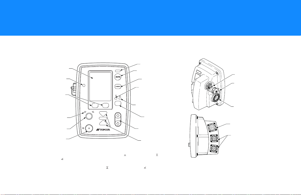
*For Proler (Milling) code, if you are using both a sonic tracker and a yoyo sensor, pressing
the Slope/Elevaton button cycles through the sonic tracker ( ), the yoyo sensor ( ), and
the slope sensor ( ).
If you are using only one elevation sensor, either sonic or yoyo, pressing the Slope/Elevation
button switches between the elevation sensor ( ) and the slope sensor ( ).
Auto Indicator LED
Auto Button
Survey Button
Elevation Indicator
LED (Green)
Slope Indicator
LED (Yellow)
Slope/Elevation
Button*
Jog Up/Down
Buttons
LCD
Light Sensor
Power On/Off
Button
Grade Adjustment
Knob
Grade Adjustment
Arrows
Menu Selection
Buttons
Grade Indicator
LEDs
USB Port
USB Cap
(Removed)
Jaw Mount
Power Connector
Sonic Tracker
or Slope Sensor
Connectors
Features
GC-35 Setup
P/N: 1001548-01
1
Page 6
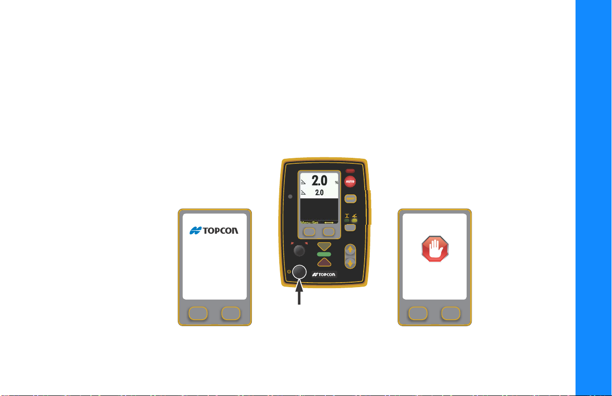
First Time Setup
Power On/O
Button
Startup Screen Shutdown Screen
GC-35
Shutting Down
Cong File Name
cong: 15
Machine Type
1. Mount the Control Box onto the bracket.
2. Connect the Sensor Cables and the Power Cable to the Control Box.
3. Power on the Control Box. See “Powering the Control Box On/Off” on page 2.
4. Set the Valve Offsets from the Performance Menu. See “Setting Valve Offsets (Raise and Lower) for Paver” on page 7.
or See “Setting Valve Offsets (Raise and Lower) for Profiler” on page 10.
Powering the Control Box On/Off
GC-35 Setup
First Time Setup
P/N: 1001548-01
2
Page 7
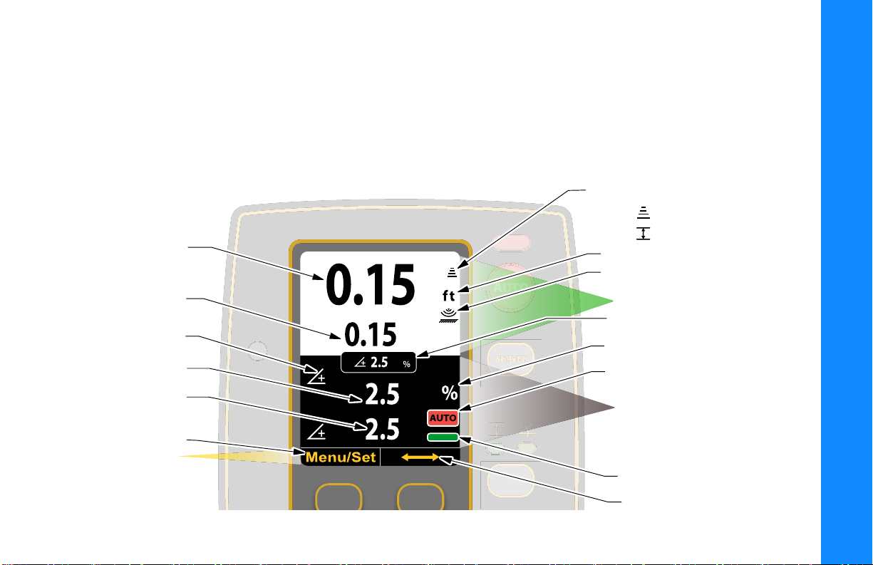
Control Screen
Elevation Set
Point Value
Actual Elevation
Sensor Reading
Slope Set Point Value
Positive/Negative
Slope Indicator Icon
Actual Slope
Sensor Reading
Menu/Set
Button Function
Display Area
Elevation Icon
Paver:
Proler:
Units (ft/in/cm)
ST-3 Surface/Stringline Mode Icon
Display Slope Box
Auto Icon
Slope Icon
Primary Control Box Display Area
Secondary Control Box
Display Area
Cross Communication
On-Grade Icon
The Control Screen displays when you power on the control box. It is your interface with the components of your
Topcon System. The Control Screen changes depending on how you have configured your Control Box and your
Topcon S y s t em .
The illustration below shows an example of a Control Box set up to display information from a secondary Control Box
set up for Slope Control.
GC-35 Setup
Control Screen
P/N: 1001548-01
3
Page 8
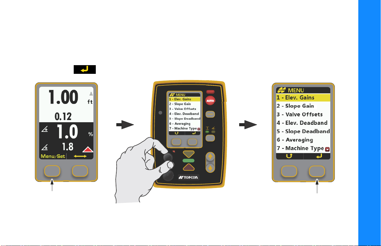
Performance Menu
Press Menu/Set Button Turn Grade Adjustment Knob
Press Enter Button
Follow these steps to access the Performance Menu, select Performance Menu items, and make changes.
1. From the Control Screen, press the Menu/Set button.
2. Rotate the Grade Adjustment Knob to scroll through the menu selections displayed on the screen, and press the Enter
button
to select a menu item.
GC-35 Setup
Performance Menu
P/N: 1001548-01
4
Page 9
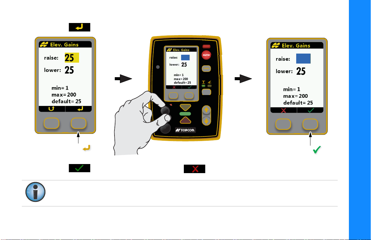
3. Press to highlight the value in blue, and then use the Grade Adjustment Knob to change the value.
Press Enter Turn Grade Adjustment Knob
Press OK
28
28
GC-35 Setup
4. Press to store the value (Figure 3), or press to cancel and revert back to the original value..
If power is interrupted to the Control Box within two seconds after making an adjustment, the Control Box does
not have time to store the new setting and reverts to previous (or original) settings.
Performance Menu
P/N: 1001548-01
5
Page 10

Table 1. Performance Menu Settings
Number Menu Item Range Default
1 Elev.Gains (Raise and Lower) 1 – 200 25
2 Slope Gain (Raise and Lower) 1 – 100 25
3 Valve Offsets 1 – 999 135
4 Elevation Deadband 1 – 30 mm 3 mm
5 Slope Deadband 0.025% – 0.75% 0.075%
6 Averaging 1 – 100 50
7 Machine Type Paver or Profiler -
8 Display Set point, + Sensor, Both sides +Sensor
9 Units in, ft, cm in
10 System Info N/A Displays the Topcon logo, copyright date, and
current firmware version. Interface to Update
Control Box and ST-3 Firmware.
11 Sonic Tracker 3 Surface, Stringline, Use at power up Surface
12 Slope Res. 0.1%, 0.5% 0.1%
13 Slope Cal. Block Off, On On
14 Language English, Deutsch, Nederlands,
Espanol, Francais
15 Box Position Left or Right Left
English
GC-35 Setup
Default settings are preset values that run most ma chi nes, except for Valve Offsets w hic h must be set by th e Op erator
at first time setup.
Performance Menu
See “Setting Valve Offsets (Raise and Lower) for Paver” on page 7.
P/N: 1001548-01
6
Page 11

Paving Applications
Setting Valve Offsets (Raise and Lower) for Paver
Set the Valve Offsets first, before setting any other Performance Menu items.
The offset value on one side of the paver may differ from the offset value on the other side of the paver. You must
verify the offset values before swapping boxes.
Never attempt to use Valve Offsets to compensate for a slower raise or lower speed of your hydraulic valves, as
it causes undershooting or overshooting in Slope Mode and can adversely affect the quality of the mat.
1. Run the paver until the hydraulic oil is at normal operating
temperature before setting the valve offsets.
2. Select Valve Offsets raise:.
3. Turn the Grade Adjustment Knob counter clockwise,
decreasing the Valve Offset - raise value until the hydraulic
cylinder no longer moves. Then slowly rotate the Grade
Adjustment Knob clockwise until the hydraulic cylinder just
begins to move up.
4. Repeat step 3 for Valve Offsets lower:.
GC-35 Setup
Paving Applications
P/N: 1001548-01
7
Page 12

Getting Started Paving Using Elevation Control
1. Setup the paver screed as you would to start paving manually.
2. Power up the Control Box and select Elevation Control by pressing the Slope/Elevation button until the green LED
above the elevation symbol lights up.
3. Position the Sonic Tracker over the grade reference.
4. Press Survey to set to On-grade.
5. Press and hold the Menu/Set button, then turn the Grade Adjustment Knob to set the display’s Elevation Setpoint
value to the desired paving thickness.
6. Switch to Auto, by pressing the Auto button and begin paving.
7. After paving several feet/meters, check the mat thickness.
8. Use the Grade Adjustment Knob as needed to make changes to the mat thickness.
Getting Started Paving Using Slope Control
1. Setup the paver screed as you would to start paving manually.
2. Make sure the slope sensor is mounted onto the transverse beam of the paver.
3. To pave using slope control you must first calibrate the slope sensor to the screed.
4. Find a smooth area where the screed can rest evenly across its entire surface. Using a laser, a Smart Level,
or a slope board, that itself has been calibrated, check the slope and direction of fall of the ground
.
GC-35 Setup
Paving Applications
Slope Cal. Block must be set to Off in the Performance Menu to calibrate the slope sensor. Slope
Cal. Block will reset to On after five minutes.
P/N: 1001548-01
8
Page 13

5. Place the screed on the ground and null it out.
6. Power up the Control Box and select Slope Control by pressing the Slope/Elevation button until the yellow LED
above the slope symbol lights up.
7. Press Survey.
a. If the On-grade bar lights up, and the screen displays a slope value that is identical to the laser or Smart
Level, press the Auto button to put the Control Box into Automatic control, and begin paving.
b.
If the slope displayed in the box does not match the surface, then you must calibrate the slope sensor.
8. Press and hold the Menu/Set button, then turn the Grade Adjustment Knob to change the display’s slope
percentage to match the slope of the surface.
9. Press the Auto button to switch to Auto, and begin paving.
Once the slope sensor is calibrated and you are ready to begin paving, you may find the existing surface does not
have the same slope as the finish design. In order to produce a smooth transition, begin paving at the existing
slope and slowly turn the Grade Adjustment Knob to change the cross slope to the correct percentage.
10. Use the Grade Adjustment Knob as needed to make changes to the slope value.
GC-35 Setup
Paving Applications
P/N: 1001548-01
9
Page 14

Profiler (Milling) Applications
Setting Valve Offsets (Raise and Lower) for Profiler
Set the Valve Offsets first, before setting any other Performance Menu items.
The offset value on one side of the profiler may differ from the offset value on the other side of the profiler. You
must verify the offset values before swapping boxes.
Never attempt to use Valve Offsets to compensate for a slower raise or lower speed of your hydraulic valves, as
it causes undershooting or overshooting in Slope Mode and can adversely affect the quality of the job.
1. Run the profiler until the hydraulic oil is at normal
operating temperature before setting the valve offsets.
2. Select Valve Offsets raise:.
3. Turn the Grade Adjustment Knob counter clockwise,
decreasing the Valve Offset - raise value until the hydraulic
cylinder no longer moves. Then slowly rotate the Grade
Adjustment Knob clockwise until the hydraulic cylinder just
begins to move up.
4. Repeat step 3 for Valve Offsets lower:.
GC-35 Setup
Profiler (Milling) Applications
P/N: 1001548-01
10
Page 15

Getting Started Milling Using Elevation Control
1. Setup the profiler as you would to start milling manually.
2. Power up the Control Box and select Elevation Control by pressing the Slope/Elevation button until the green LED
above the elevation symbol lights up.
If you are using both a sonic tracker and a yoyo sensor, pressing the Slope/Elevaton button cycles
GC-35 Setup
3. Position the Sonic Tracker over the grade reference or the side blade when using yoyo sensors.
4. Gradually lower the drum so it is just about the scrape the surface at both sides.
5. Press Survey to set to On-grade.
6. Press and hold the Menu/Set button, then turn the Grade Adjustment Knob to set the display’s Elevation Setpoint
value to zero cutting depth.
7. Switch to Auto, by pressing the Auto button and begin milling. Use the Grade Adjustment Knob to gradually cut to
the desired depth
8. After milling several feet/meters, check the cutting depth.
Profiler (Milling) Applications
through the sonic tracker
If you are using only one elevation sensor, either sonic or yoyo, pressing the Slope/Elevation button
switches between the elevation sensor
, the yoyo sensor , and the slope sensor .
and the slope sensor .
.
P/N: 1001548-01
11
Page 16

9. Use the Grade Adjustment Knob as needed to make changes to the cutting depth.
Once steps 1-6 have been done when using yoyo sensors, the actual cutting depth will always
be shown. Only steps 7 to 9 will be required.
Getting Started Milling Using Slope Control
1. Setup the profiler as you would to start milling manually.
2. Make sure the slope sensor is mounted parallel to the cutting drum as close as possible to the drum.
3. To mill using slope control you must first calibrate the slope sensor to the cutting drum.
4. Find a smooth area where the drum can rest evenly across its entire surface. Using a laser, a Smart Level, or a slope
board, that itself has been calibrated, check the slope and direction of the fall of the ground.
Slope Cal. Block must be set to Off in the Performance Menu to calibrate the slope sensor.
5. Place the drum on the ground on the same location as the slope was measured.
6. Power up the Control Box and select Slope Control by pressing the Slope/Elevation button until the yellow LED
above the slope symbol lights up.
7. Press Survey.
a. If the On-grade bar lights up, and the screen displays a slope value that is identical to the laser or Smart
Level, press the Auto button to put the Control Box into Automatic control, and begin milling.
GC-35 Setup
Profiler (Milling) Applications
P/N: 1001548-01
12
Page 17

b. If the slope displayed in the box does not match the surface, then you must calibrate the slope sensor.
8. Press and hold the Menu/Set button, then turn the Grade Adjustment Knob to change the display’s slope
percentage to match the slope of the surface.
9. Press the Auto button to switch to Auto, and begin milling.
Once the slope sensor is calibrated and you are ready to begin milling, you may find the existing surface does not
have the same slope as the finish design. In order to produce a smooth transition, begin milling at the existing
slope and slowly turn the Grade Adjustment Knob to change the cross slope to the correct percentage.
10. Use the Grade Adjustment Knob as needed to make changes to the slope value.
GC-35 Setup
Profiler (Milling) Applications
P/N: 1001548-01
13
Page 18

General Features
0.20
0.18
0.40
0.40
Turn On
AUTO
5
2
33
Turn Grade
Adjustment
Knob to
Desired Value
4
Press
and Hold
Menu/Set
Button
Press Survey
Turn O
AUTO
1
1
Turn Grade
Adjustment
Knob to
Desired Value
2
Press
and Hold
Menu/Set
Button
0.20
0.18
0.40
0.38
Adjusting the Setpoint Value Before You Start
Adjusting the Setpoint value does
not change the existing depth, it
only changes the reference number
viewed on the display
The Setpoint value changes to Red
when you turn the knob.
Adjusting the Setpoint Value While in Automatic Control
GC-35 Setup
General Features
P/N: 1001548-01
14
Page 19

Cross Communication
Primary Control BoxPrimary Control Box
Secondary Control Box
2.5
2.5
0.15
0.15
Cross Communicaton
Indication Arrows
Cross Communication
- Press and Hold to
Make Changes to
Secondary Control Box
Pressing the Cross Communication button allows you to remotely control a secondary Control Box. When the Cross
Communication Indication Arrows display on the Control Screen, Cross Communication is active.
the Control Screen shows the settings of the secondary box.
1. Press and hold Cross Communication.
Red double arrows display on the screen once cross communication with the secondary Control Box
establishes.
The bottom half of
GC-35 Setup
General Features
P/N: 1001548-01
15
Page 20

2. While holding Cross Communication, you can view or make the following changes to the settings in the secondary
box:
•
Switch the secondary Control Box into Automatic or Manual mode.
•
Adjust the slope or elevation values using the Grade Adjustment Knob.
•
Survey to On-grade.
•
Switch between Elevation/Slope control.
•
Jog Up/Down.
The Menu/Set Button and access to the secondary Control Box’s Performance Menu is disabled while in Cross
Communication.
3. When finished, release Cross Communication.
Setting Surface or Stringline Mode for the ST-3
GC-35 Setup
When using a Sonic Tracker 3 (ST-3), you can select either
Menu
the
Use at power up
is Surface.
1. From the Performance Menu select Sonic Tracker 3 and press the press the Enter button .
2. Press either Surface or Stringline.
3. Check the Use at power up check box to lock this setting to Stringline Mode when the Control Box powers on and
off, if desired, otherwise the Control Box always powers up with the ST-3 set to Surface Mode.
General Features
Surface
. Use Surface mode when tracking a surface, or Stringline when tracking a stringline with your ST-3. By checking
check box, the Control Box remembers your preferred setting at power up. The default setting
P/N: 1001548-01
or
Stringline
mode from the
Performance
16
Page 21

GC-35 Setup
General Features
If using the ST-3 Sonic Tracker with a Topcon System Five™ Control Box, only Surface Mode is available. To use
Stringline Mode, you must use a GC-35 Control Box.
P/N: 1001548-01
17
Page 22

Loading and Saving Machine Configuration Files
From the GC-35 Performance Menu you can load and save machine configuration files from a USB drive and/or
select files from a list. You can save a maximum of twenty machine configuration files to the GC-35.
Loading Files
1. Insert a USB key with the machine configuration file into the GC-35’s USB port.
2. From the Performance Menu, select Machine Type, and press the Enter button .
3. Select Load from USB, and press Enter .
4. Choose the configuration file, and press .
5. To use the configuration file, select Use, and press .
Saving Files
1. From the Performance Menu, select Machine Type, and press the Enter button .
2. Select Enter Name/Save, and press Enter .
3. Use the adjustment knob to cycle through characters (letters A-Z and numbers from 0-9) to name the configuration
file, and press
.
GC-35 Setup
4. To delete a character, use the knob to cycle through the characters until the symbol appears. Press .
5. When you are finished naming the file, press .
Loading and Saving Machine Configuration Files
P/N: 1001548-01
18
Page 23

6. To save and use the configuration file, select Use, and press .
7. To save the configuration file to a USB key, insert a USB key into the USB port, select Copy to USB, and press
.
Selecting Language Type
1. From the Performance Menu, select Language, and press the Enter button .
2. Select from English, Deutsch, Nederlands, Espanol, or Francais to change the user interface language on the
Control Box, and press .
GC-35 Setup
Loading and Saving Machine Configuration Files
P/N: 1001548-01
19
Page 24

• • • • • •
Troubleshooting
In Slope Control, Slow Tow Point Cylinder Response in One Direction (Raise or Lower)
Solution:
1. From the Performance Menu, decrease the Valve Offset value of the direction (either Raise or Lower) in which the tow
point cylinder moves faster.
2. If necessary, adjust both the Slope and Elevation Gains in the Performance Menu to increase overall
responsiveness of the valve.
When using Slope Control, do not raise the Valve Offset value of the direction (either Raise or Lower) in which
the tow point cylinder moves slower to compensate for the slow response time, as this can cause overshooting
or undershooting On-grade.
Sensor Readings on the Control Screen Fluctuating Rapidly, and Grade Lights Flash High and Low and Do Not Stay On-grade
Solution:
1. Check that Trackers are between 14 and 24 inches from reference.
2. If there are gusty winds, lower Tracker closer to reference. Approximately 14 to 16 inches.
3. Move Tracker away from gusty heat source, such as engine fan exhaust.
4. Verify Tracker is not picking up erroneous signals from undesired reference. Example: Debris such as rocks,
parts of the machine obstructing the sonics.
Trou bl eshoo ti ng
P/N: 1001547-01
20
Page 25

5. If using stringline, verify that the line is not bouncing.
Sonic Tracker Picks Up the Ground, but Does Not Pick Up a Stringline
Solution:
1. To verify if the Tracker detects the stringline, set up the Tracker at least 16 inches over the stringline, then pull up on
the stringline slowly, and verify that the sensor reading on the Control Box’s Control Screen immediately changes.
2. Verify that Tracker is at least 14 inches above the stringline.
3. Smooth, steel wire is not recommended. Use minimum 1/16 inch diameter string for elevated stringline or
averaging ski. Use 1/8 inch string for surface stringline.
4. If using an ST-3, make sure the Sonic Tracker 3 is set to Stringline in the Control Box’s Performance
Menu and that the ST-3 is aligned with the stringline.
Tow Point Cylinders Moving too Fast or Too Slow (Strange Valve Response)
Solution:
1. Check that the machine power is on and all switches for automatic control on the machine are in the proper position.
2. Check that all cables are properly and securely connected to the Control Box and the machine.
3. Disconnect cables and inspect them for damage or contamination. Clean all connections with an electrical
contact cleaner.
4. Check that Trackers are between 14 and 24 inches from reference.
5. If there are gusty winds, lower Tracker closer to reference. Approximately 14 to 16 inches.
6. Check that the Valve Offsets are set correctly.
7. Check that the Elevation Gain and Slope Gain are set correctly.
Troubleshooting
P/N: 1001547-01
21
Page 26

• • • • • •
Safety Warnings
General Warnings
This product should never be used:
•
Without the operator thoroughly understanding the Operator’s Manual and Quick Reference Guide.
•
After disabling safety systems or altering the product.
•
With unauthorized accessories.
•
Without proper safeguards at the job site.
•
Contrary to applicable laws, rules, and regulations.
TPS products should never be used in dangerous environments. Use in rain or snow for a limited period is permitted.
Tampering with the unit by the operator or non-factory authorized technicians will void the unit’s warranty:
• Do not attempt to open the unit and modify any of its internal components.
• Do not short circuit.
Safety Warnings
P/N: 1001548-01
22
Page 27

Page 28

www.topconpositioning.com
Specifications subject to change without notice. All rights reserved. 1001548-01 Rev C 01/17 ©2017 Topcon Corporation
 Loading...