

Page 1
CCVV--55000000SS iinnssttaallllaattiioonn m
)
((VVeerr..44)
TTOOPPCCOONN CCOORRPPOORRAATTIIOONN
JJuullyy 22001111
maannuuaall
Page 2

Index
1. Basic configuration................................................................................................................................................2
2. Mounting the CV-5000S Phoropter head...........................................................................................................4
3. Connection of head/power supply and controller .............................................................................................5
4. Installation of PC software (setup 3)...................................................................................................................7
5. Connection with chart .........................................................................................................................................14
6. Connection with refraction instruments............................................................................................................28
7. Output subjective data to PC.............................................................................................................................44
8. Network system 1................................................................................................................................................52
9. Network system 2................................................................................................................................................55
10. Network system 3..............................................................................................................................................59
11. Network system 4..............................................................................................................................................64
12. Network system 5..............................................................................................................................................69
13. Network system 6..............................................................................................................................................72
14. Details of setting menu............................................................................................................................... ......77
15. Customizing pictures and movies (PC-50S only).........................................................................................78
16. Export and import settings with USB memory ..............................................................................................80
17. Update KB-50S..................................................................................................................................................81
1
Page 3
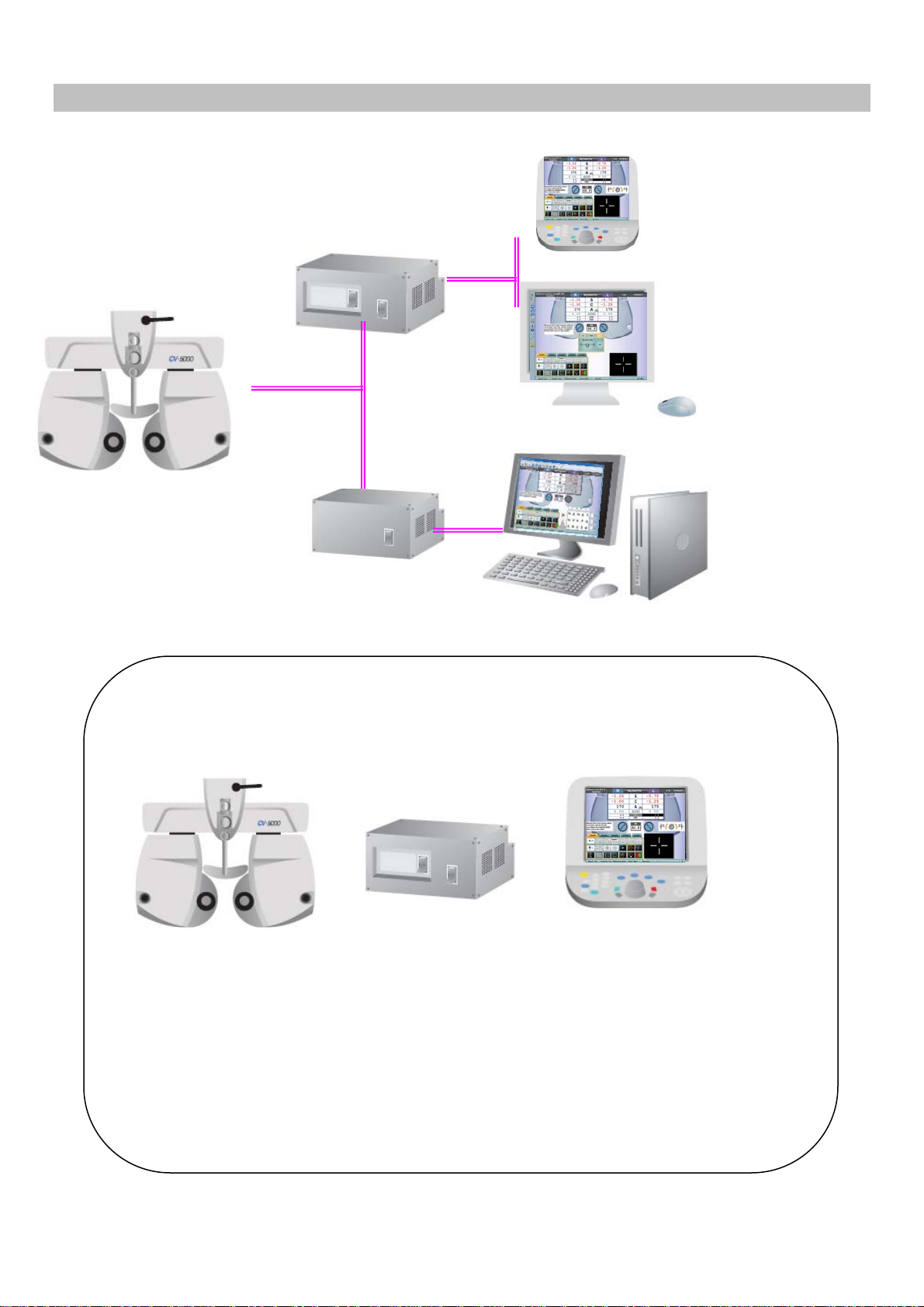
1. Basic configuration
SETUP 1
(KB-50S)
SETUP 2
(MONITOR & MOUSE)
SETUP 3
(PC)
SETUP 1 Basic components
2. 3.
1.
1. 432239501 Phoropter head with arm
2. 432249700 Power supply with built-in PC
with built-in printer,
with measuring head connection cable and power cord.
3. 432259500 KB-50S (one dial controller)
with USB/DC interface cable.
2
Page 4
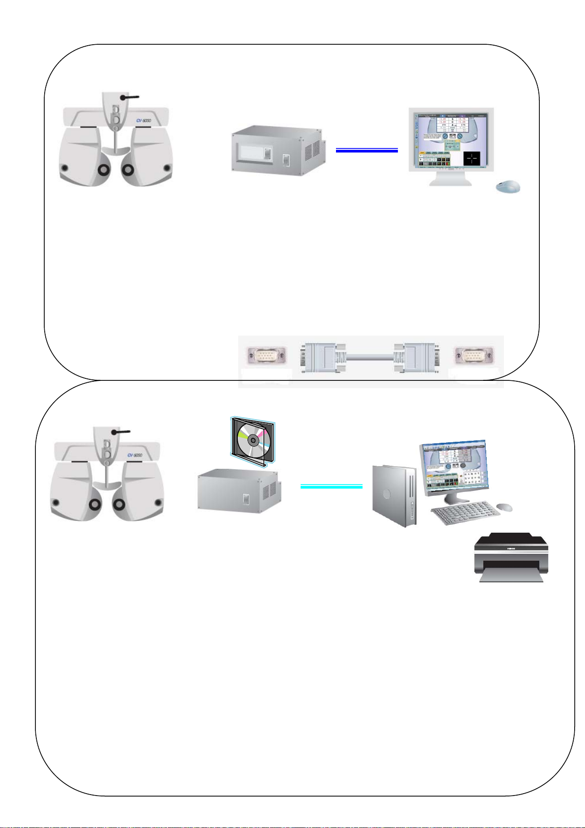
SETUP 2 Basic components
1.
1.432239501 Phoropter head with arm.
2.432249700 Power supply with built-in PC
with built-in printer,
with measuring head connection cable and power cord.
3. Monitor (locally arrange)
4. USB mouse (locally arrange)
5.VGA cable (locally arrange)
2.
3.
5.
Monitor
z analogue
z VGA interface
z 1024x768 resolution or more
4.
SETUP3 3 Basic component
1.
2. 4. 3.
1.432239501 Phoropter head with arm.
2. 432249702 Power supply
with measuring head connection cable and power cord.
(without printer)
with CV-5000PC software.
3. 418120002 RS-232C serial cable (Din8 – Dsub9) (5m)
or 424290061 RS-232C serial cable (Din8 – Dsub9) (10m)
or RS-232C-USB conversion cable (locally arranged)
4. PC (locally arrange)
Monitor (DVI or VGA), USB mouse / Keyboard, Printer
3
PC requirements
Windows XP Professional SP3
Windows 7 Professional 32bit
Windows 7 Professional 64bit
In case of Internet Explorer Ver.8, a
security patch file “KB2482017” should be
installed.
9 1280x1024 resolution monitor
9 At least one serial port.
Page 5

2. Mounting the CV-5000S Phoropter head
See the instruction manual CV-5000S as well.
2-1. Level adjustment
2-2. Check the face shield and forehead rest.
2-3. Near point head and rod installation.
4
Page 6
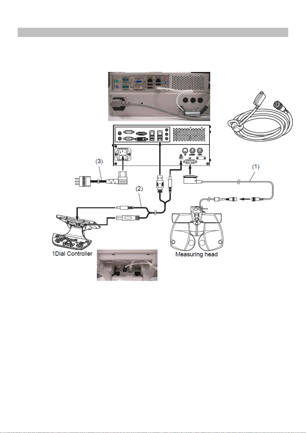
3. Connection of head/power supply and controller
3-1. SETUP 1
Connect power supply box, measuring head, KB-50S and power cord.
Power cord
Measuring head connection cable
KB-50S USB/DC
interface cable.
5
Page 7
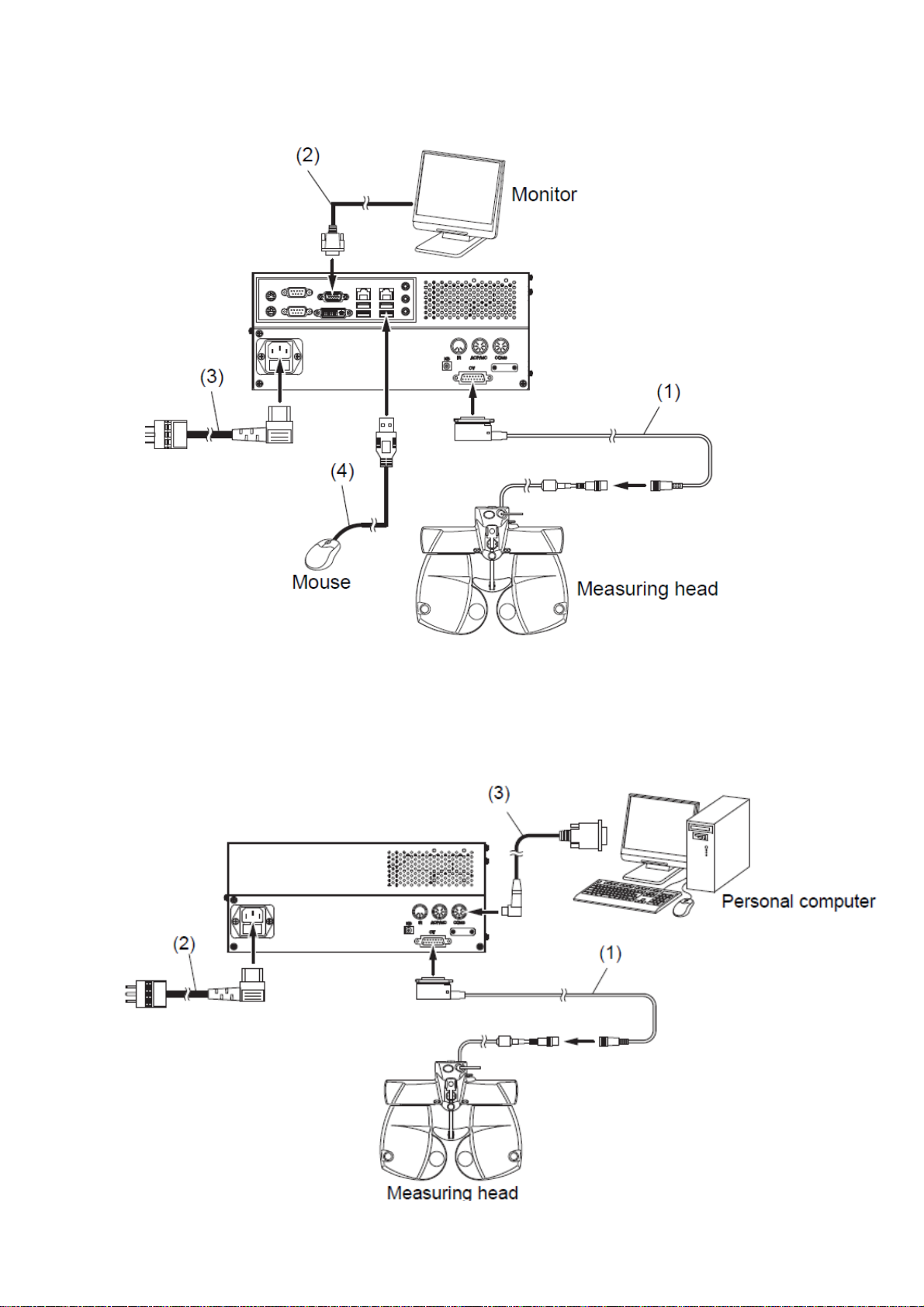
3-2. SETUP 2
Connect power supply box, measuring head, analogue monitor, mouse, and power cord.
Power cord
VGA cable
Measuring head connection cable
3-3. SETUP 3
Connect power supply box, measuring head, PC and power cord.
RS-232C cable
Measuring head connection cable
Power cord
6
Page 8
4. Installation of PC software (setup 3)
4-1. PC requirements
Windows XP Professional SP3
Windows 7 Professional 32bit
Windows 7 Professional 64bit
* In case of Internet Explorer Ver.8, install Microsoft security update program “KB2482017”.
At least one serial port is necessary (to connect power supply box and PC), and make sure that COM port is
recognized.
*Monitor resolution must be 1280 x 1024 or more.
4-2. Install the software.
4-2.1. Turn on the PC
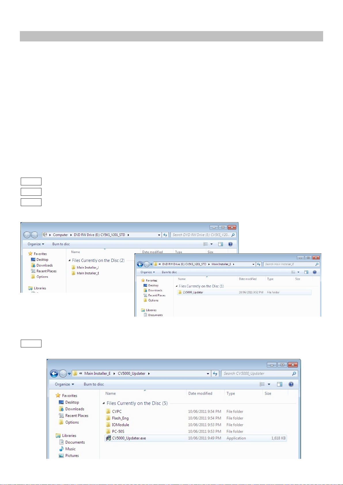
4-2.2. Insert the CV-5000 CD into CD/DVD drive of the PC.
4-2.3. Select [Main Installer_E] _ [CV5000_Updater]
4-2.4. Click [CV5000_Updater.exe].
7
Page 9
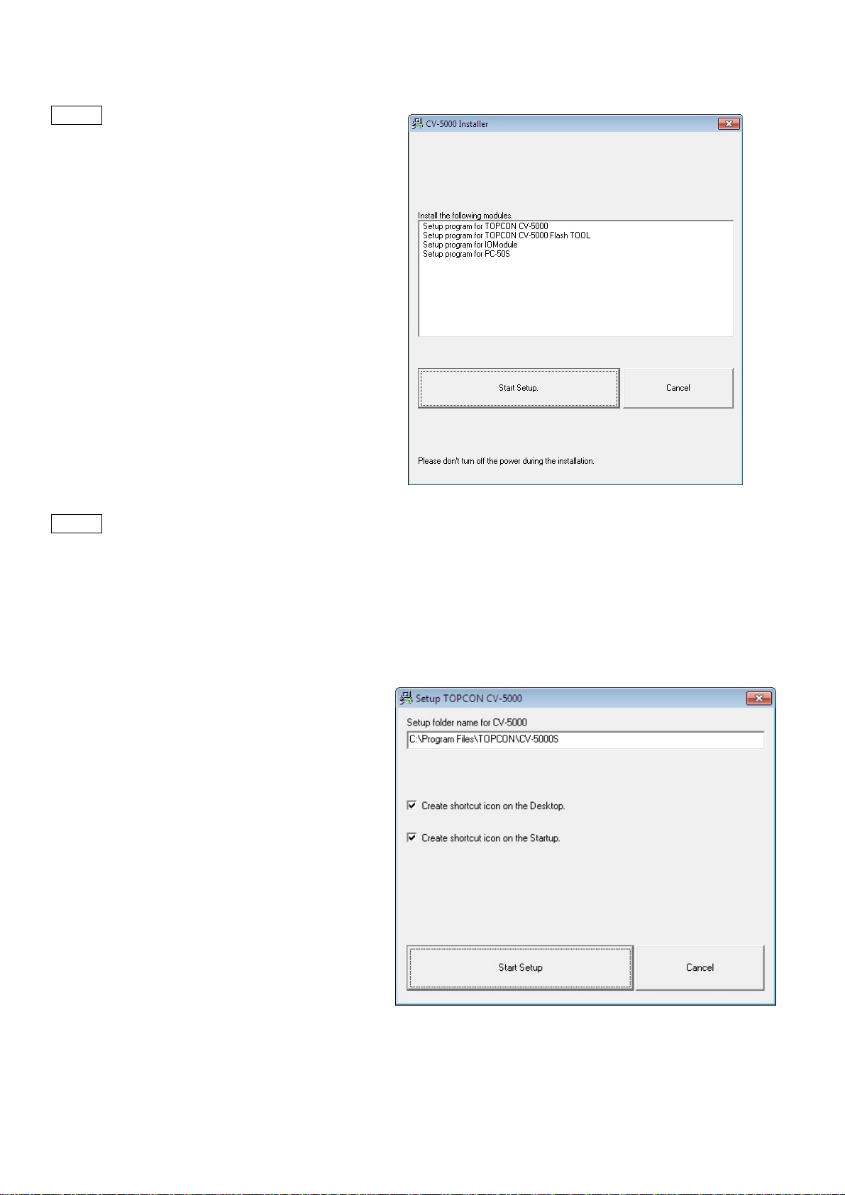
4-2.5. Click [Start Setup]
4-2.6. Check the installation destination folder.
(Default is C:¥ProgramFiles¥TOPCON¥CV-5000S)
Tick in [Create shortcut icon on the Desktop]
Tick in [Create shortcut icon on the Startup]
Click [Start Setup].
8
Page 10
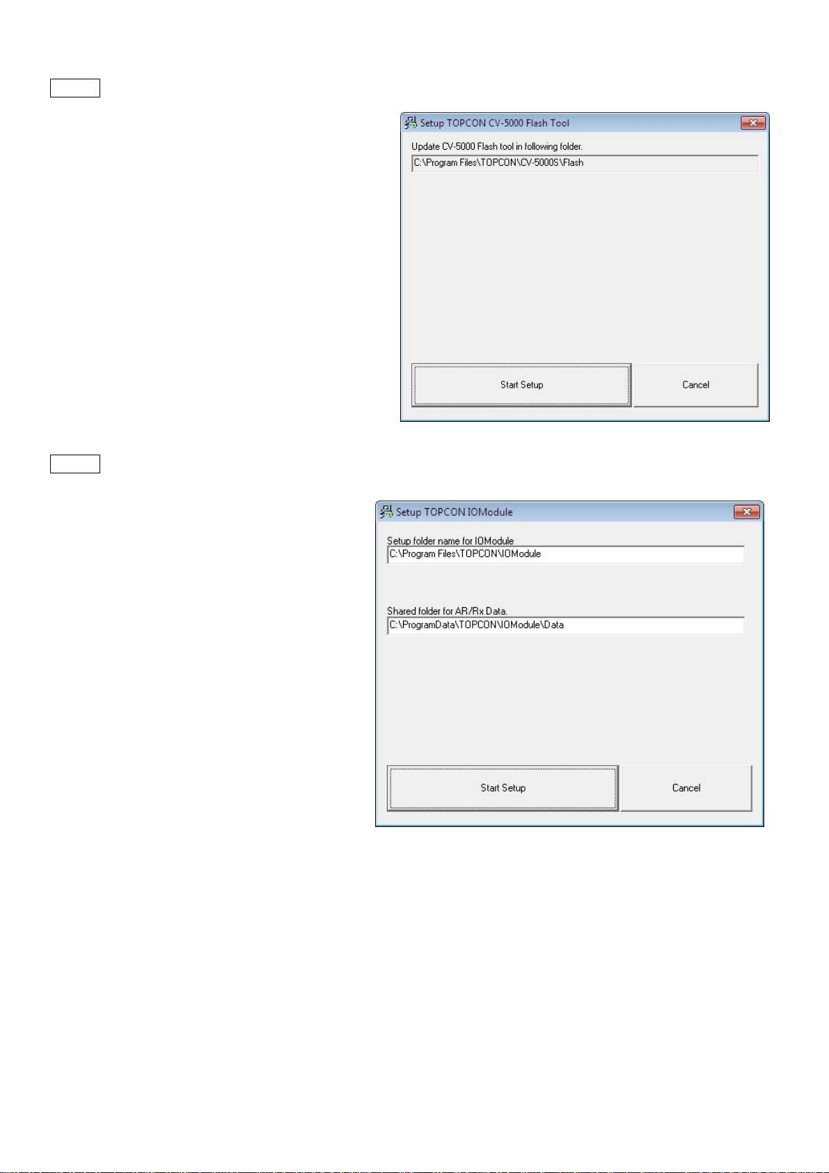
4-2.7. Click [Start Setup]
4-2.8. Click [Start Setup]
9
Page 11
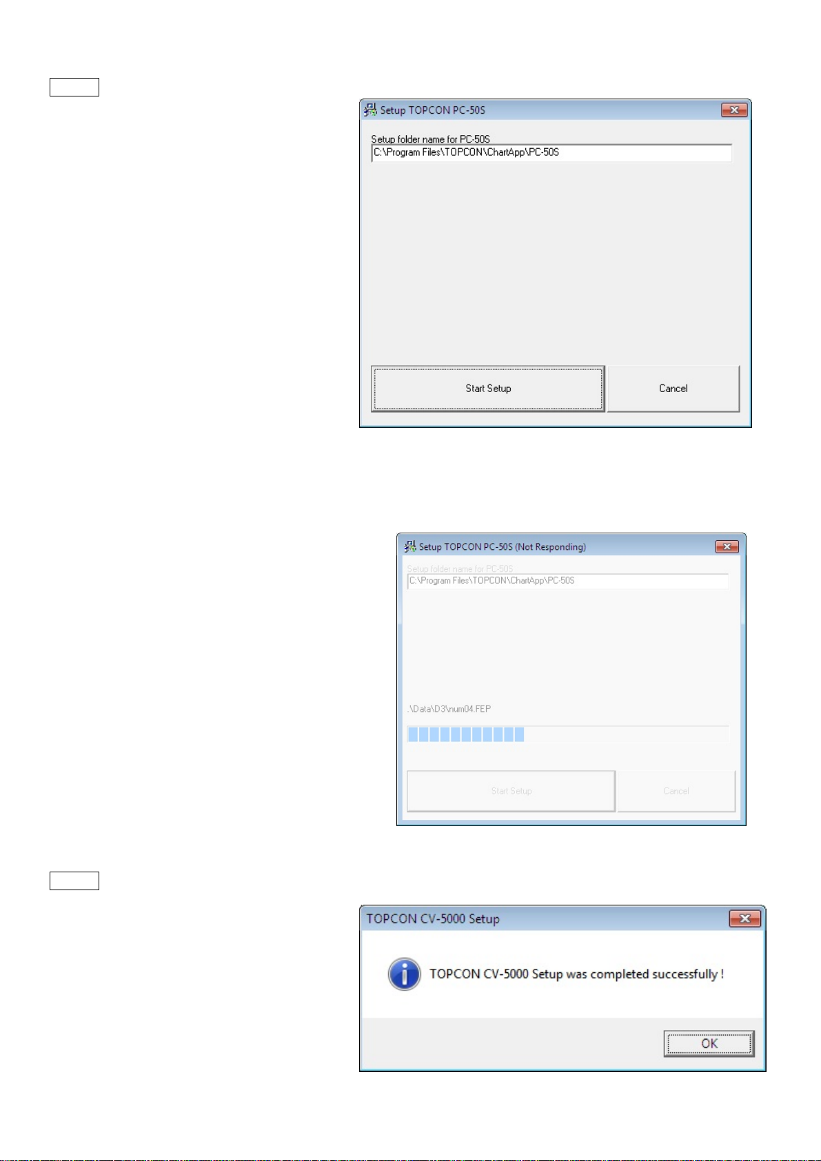
4-2.9. Click [Start Setup]
z Please wait if you find the “not responding”.
4-2.10. Click [OK] to finish installation.
10
Page 12
4-3. Initial settings
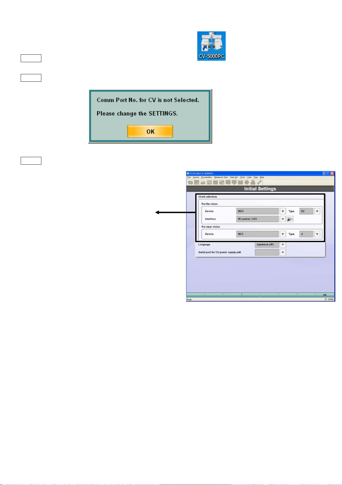
4-3.1. Power up the power supply box and start [CV-5000PC]
4-3.2. The following dialogue appears to check COM port. Click OK
4-3.3. In [Initial Settings], select followings.
[For Far Vision]
Device: the chart device to use.
ACP8, MC-3, PC-50, PC-50S or CC-100
Type: the chart type to use.
software.
Chart type (A, B(M/F), C, D, F, H, IS)
Chart monitor selection: (in case of PC-50S)
Please select #: Plug and play monitor (=PC-50S)
Interface: (in case of ACP/MC/PC-50)
2 options of signal communication.
-IR emitter
-RS232C
[For Near Vision]
Device: the chart device to use
NC-3, NV20
Type: E/J
* Settings can be changed later, this process is necessary for start the software first time.
11
Page 13
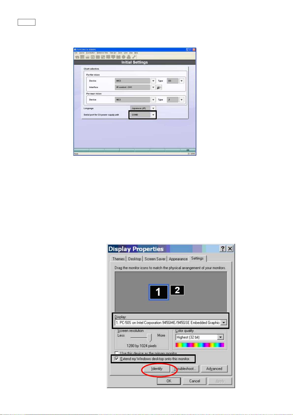
4-3.4. Select [serial port for CV power supply unit].
Select in the pull down menu, as there are COM numbers which are recognized are listed.
4-4. PC-50S setting.
In case of using PC-50S, adjust the display setting.
(1) Right click on the desktop, and select [Display Properties]
(2) Select [Settings]
(3) Select [Display]_[#:Plug and play monitor].
(4) Click [Identify] and make sure the selected number is displayed on PC-50S.
(5) Make sure the resolution is “1280x 1024” and 32 bit color.
(6) Tick in [Extend my Windows desktop onto this monitor].
(7) Click [OK]
12
Page 14
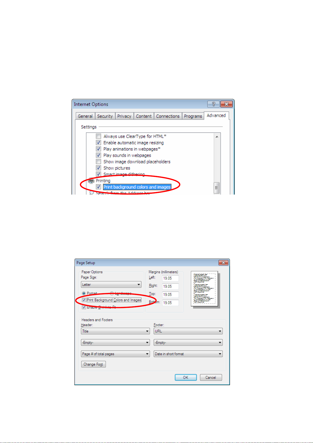
4-5. Printer setting
SETUP 3 does not have the built-in printer, thus please arrange a printer for PC if required.
The following is recommended to print setting to have report much clearer to see with highlights on title.
In case of Internet Explorer 6 / Internet Explorer 7.
select [Internet Explorer]_[Tools]_[Internet Options]_[Advanced]
Tick in “Print background colors and images”.
In case of Internet Explorer 8,
select [Internet Explorer]_[Files]_[Page setup] *If the menu bar is hidden, press [Alt] key.
Tick in “ Print Background Colors and Images “.
13
Page 15
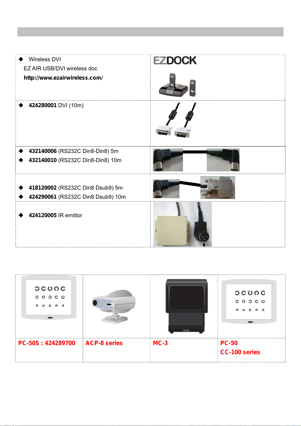
5. Connection with chart
General information about cables
Wireless DVI
EZ AIR USB/DVI wireless doc
http://www.ezairwireless.com/
424280001 DVI (10m)
432140006 (RS232C Din8-Din8) 5m
432140010 (RS232C Din8-Din8) 10m
418120002 (RS232C Din8 Dsub9) 5m
424290061 (RS232C Din8 Dsub9) 10m
424120005 IR emittor
Chart lineups
PC-50S : 424289700 ACP-8 series
MC-3
14
PC-50
CC-100 series
Page 16
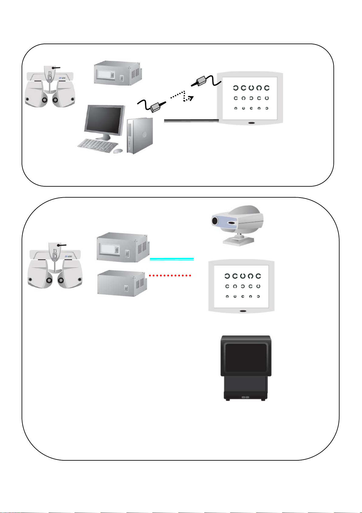
General layout of CV-5000S system and chart device
SETUP 1 or 2
SETUP 3
(1)
(1) EZAir wireless DVI
(2) 424280001 DVI (10m)
SETUP 1, 2, or 3
(2)
PC-50S
Exclusively in use with CV-5000S
No remote controller is available
ACP-8 series
(1)
PC-50
(2)
CC-100 series
(1) ACP/MC-3 : 432140006 (RS232C Din8-Din8)
PC-50 : 424290061 (RS232C Din8 Dsub9)
(2) IR emittor 424120005
MC-3
Remote controller is available
(optional accessory)
Stand alone use is available
15
Page 17
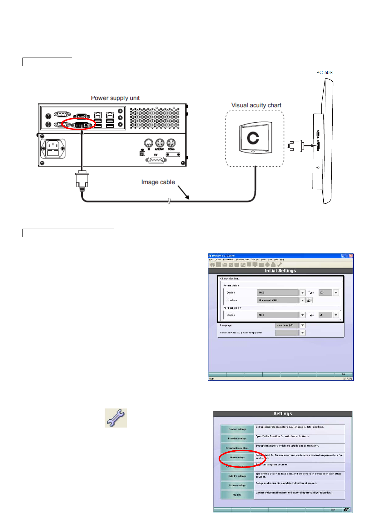
5-1. PC-50S for SETUP 1 and 2.
Please see Instruction Manual PC-50S for how to install PC-50S.
5-1.1. Cabling
Connect DVI cable to DVI socket of power supply.
DVI cable
5-1.2. Settings in CV-5000S
(1)When CV-5000S and PC-50S first time, the initial settings screen comes up.
For other cases,
(SETUP1) Press [Shift]&[Menu] button, and select [Settings]_[Chart Settings]
(SETUP2) Click [Settings]
icon and
click [Chart Settings].
16
Page 18
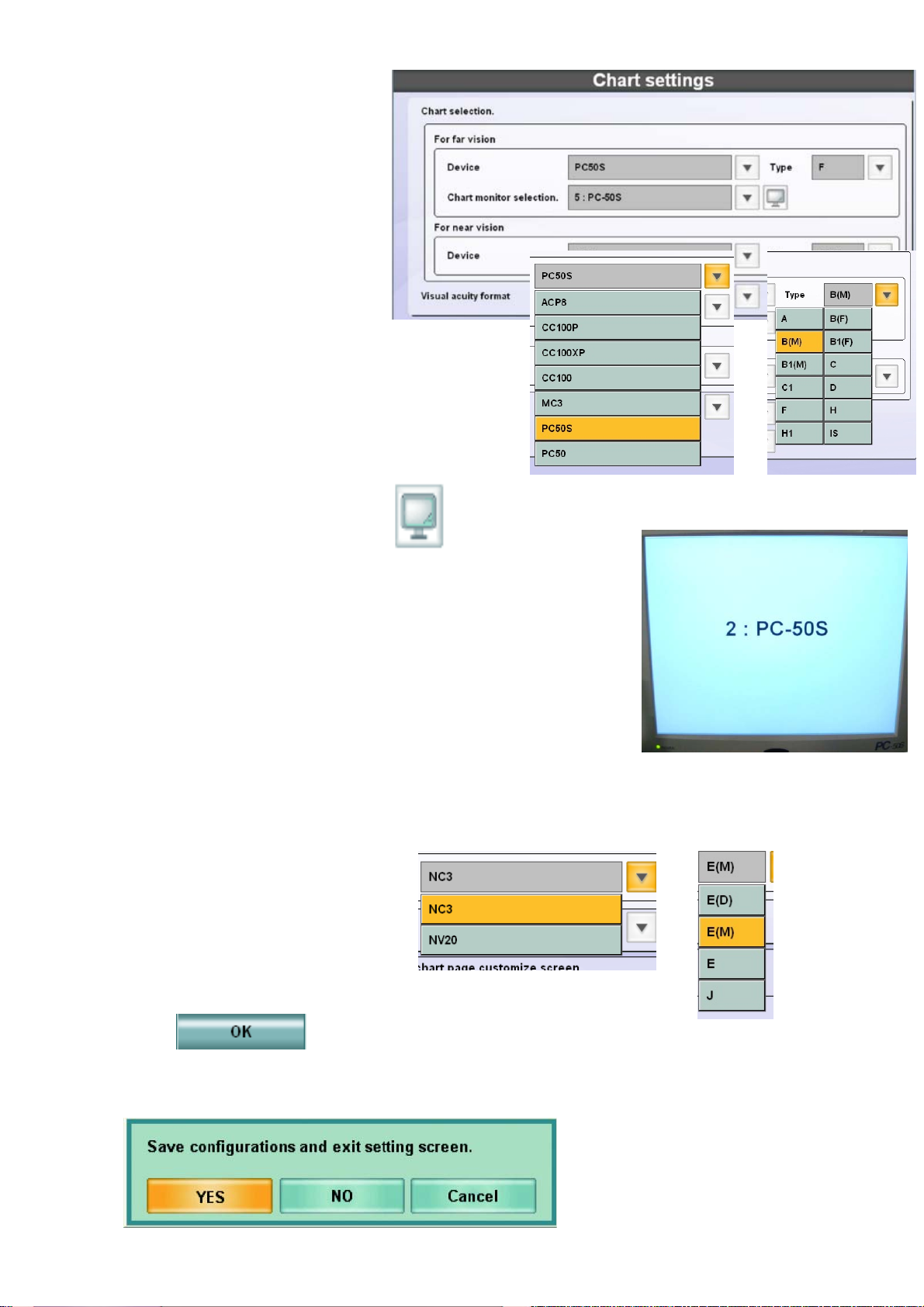
(2) Select “For far vision”,
Device = PC-50S
Type = Chart A, B, E, F,H
(at your convenience)
Chart Monitor Selection
= #:PC-50S
(#: is automatically assigned)
z #:Plug and play monitor
stands for the monitor for control in Setup2.
(2)’ (Especially in SETUP2) Touch the mark,
so that you can see the
monitor for control ( #: plug and play monitor ) and #: PC-50S are
recognized.
(PC-50S displayÆ)
(3) Select “For near vision”,
Device : NC3 or NV20
Type : E
(4) Touch [OK]
(5) Touch [Yes]
17
Page 19
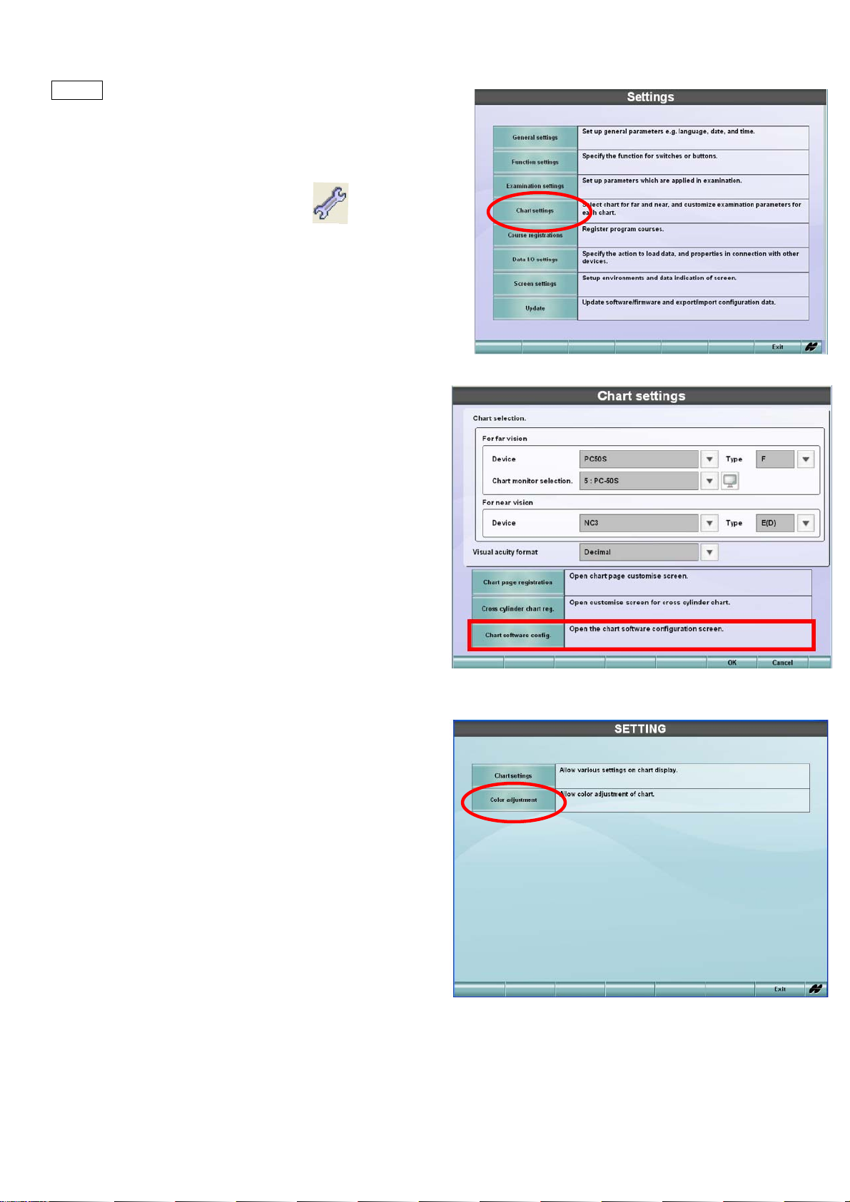
5-1.3. Settings in PC-50S.
(1)
(SETUP1) Press [Shift]&[Menu] button, and select
[Settings]_[Chart Settings]
(SETUP2) Click [Settings] icon and
click [Chart Settings].
(2) Select [Chart Software Config.]
(3) Select [Chart Settings] .
18
Page 20
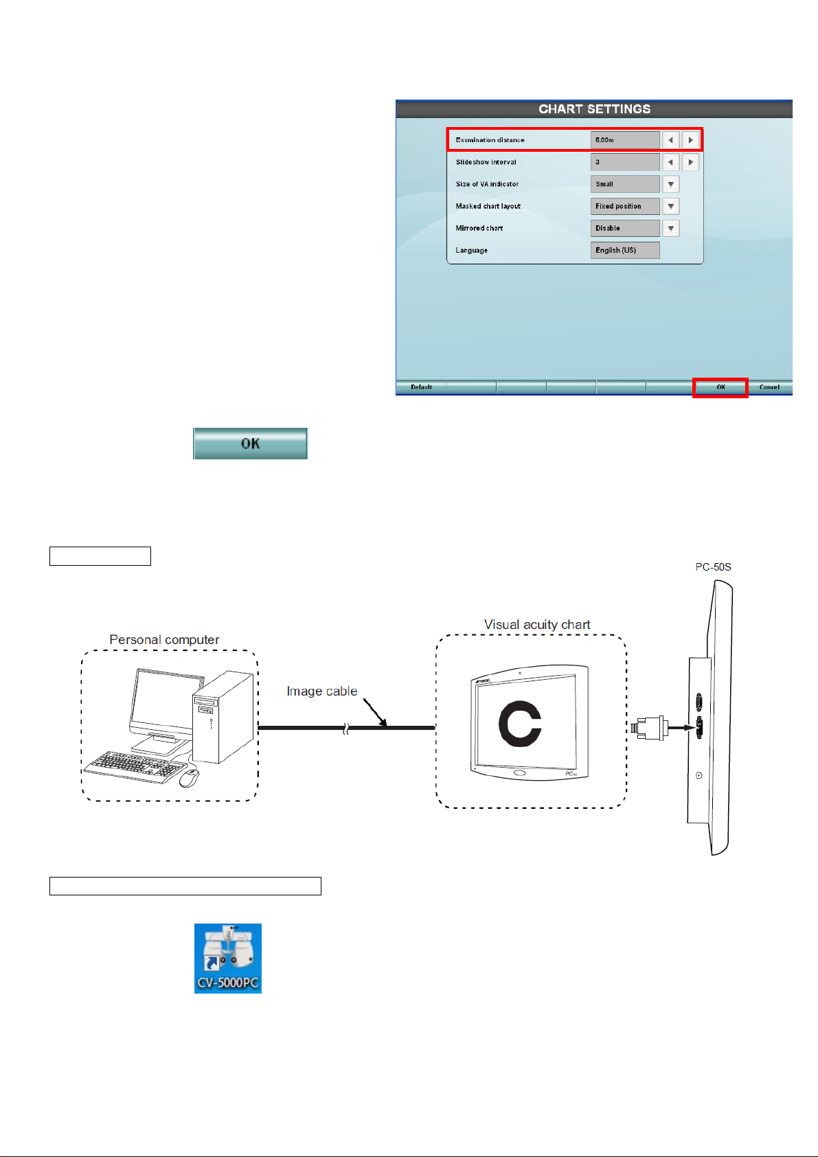
(4) Select each item.
*Examination distance(2.5m-6.0m)
*slideshow interval (3-10 secs)
*Size of VA indicator
*Masked chart layout
*mirrored chart
*Language (no need to set)
(5) Touch OK
5-2. PC-50S for SETUP 3
5-2.1. Cabling
Connect DVI cable between PC-50S and computer.
DVI cable
5-2.2. Settings in CV-5000S SETUP3
(1) Start CV-5000PC
19
Page 21
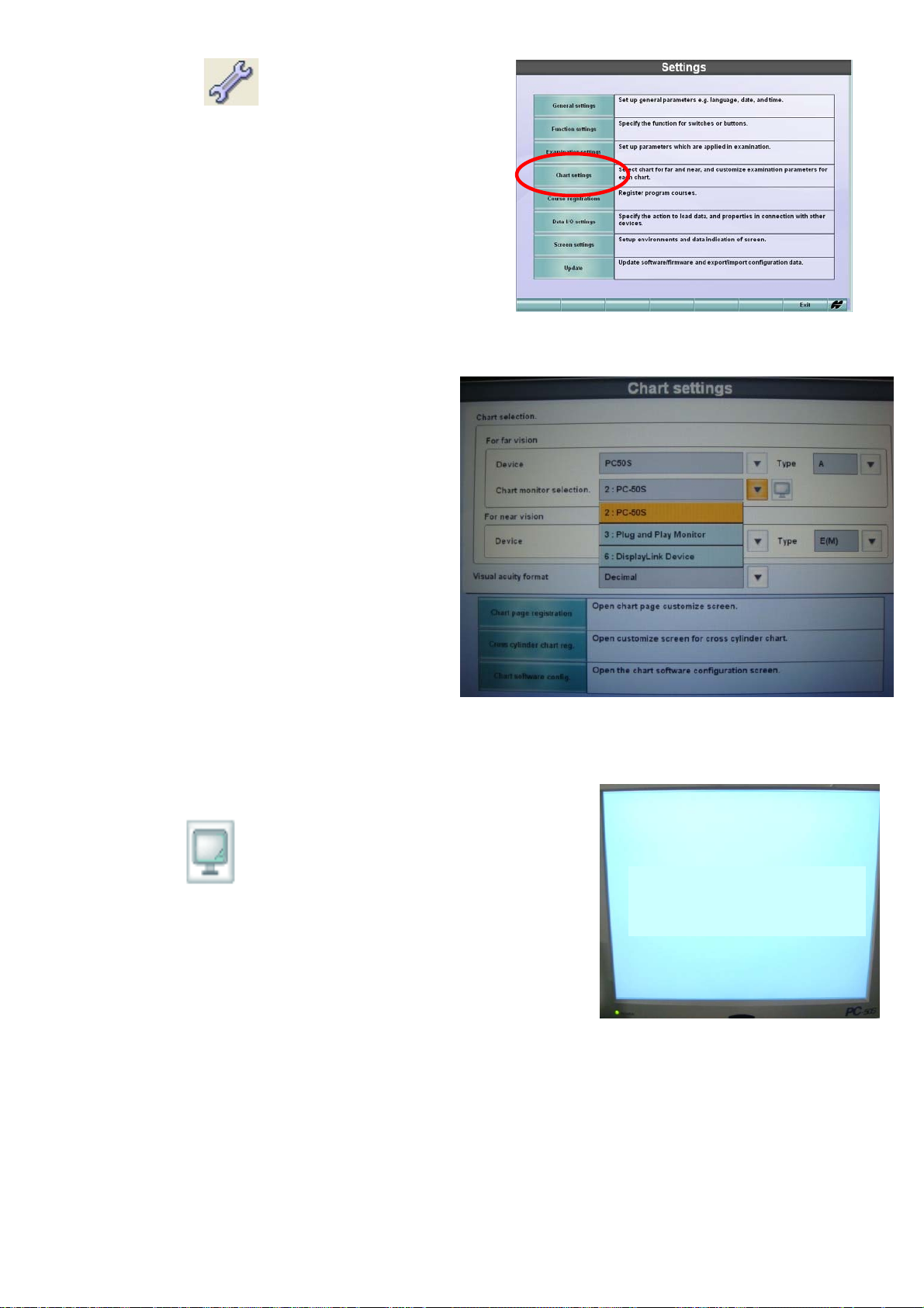
(2) Click [Settings] and select [Chart Settings]
(3) Select in [For far vision],
Device = PC-50S
Type = Chart A, B, E, F,H
(at your convenience)
Chart monitor selection =
# : Plug and Play Monitor
Select in [For near vision]
Device = NC3/NV20
Type = E
Touch the mark,
so that you can see
# : Plug and Play Monitor is recognized.
(PC-50S displayÆ)
# : Plug and Play Monitor
20
Page 22
5-2.3. PC-50S
See 5-1.3
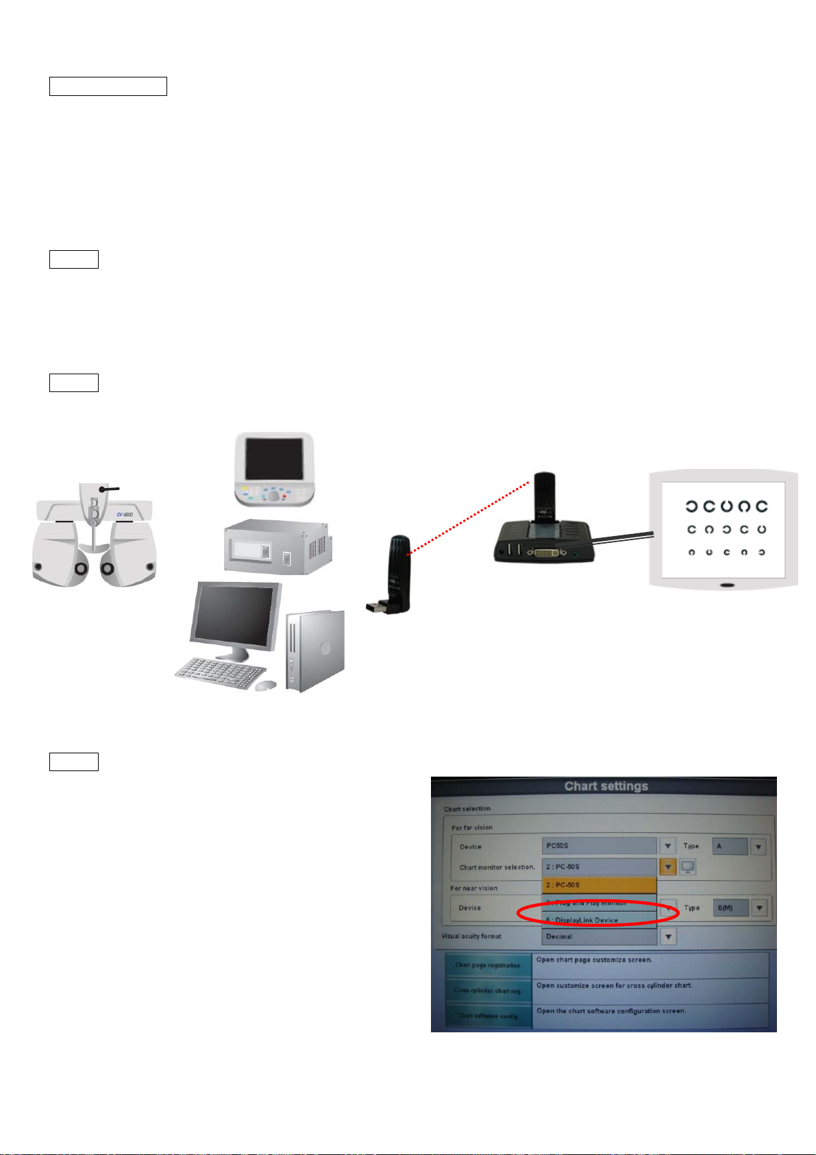
5-3. PC-50S Wireless connection for SETUP 1&2, 3
EZ AIR USB/DVI wireless doc is only confirmed device.
No other manufacturer’s cannot be used.
5-3.1. Connect USB transmitter to USB socket on control box (SETUP 1/2), KB-50S or on PC (SETUP3).
*Install USB driver for EZ Air in case of SETUP3. Control box (SETUP 1/2) is pre-installed with the driver for
EZ Air.
5-3.2. Connect USB doc and PC-50S by DVI cable.
5-3.3. Select [#:Display Link Device].
DVI cable
21
Page 23

5-4. PC-50 / CC-100 series /ACP-8 / MC-3 (RS-232C)
Please see instruction manual for how to set up ACP-8/MC-3/PC-50.
5-4.1. Connect the chart to ACP/MC port of power supply with serial cable.
For ACP/MC-3 432140006 (RS232C Din8-Din8)
For PC-50 424290061 (RS232C Din8 Dsub9)
(SETUP 1/2)
(SETUP 3)
22
Page 24
5-4.2. Settings in CV-5000S
(1)
(SETUP1) press [Shift]&[Menu], and
select [Settings]_[Chart Settings]
(SETUP2,3) click [Settings ]
and
select [Chart Settings]
(2) select each item in [For far vision]
Device : ACP-8 or MC-3 or PC-50
Type : A, B, F, or H
Interface : RS-232C
5-4.3. in case of PC-50
(1)Turn on PC-50 power.
(2)Press Menu switch No.1 (left) to show [Main Menu].
23
Page 25
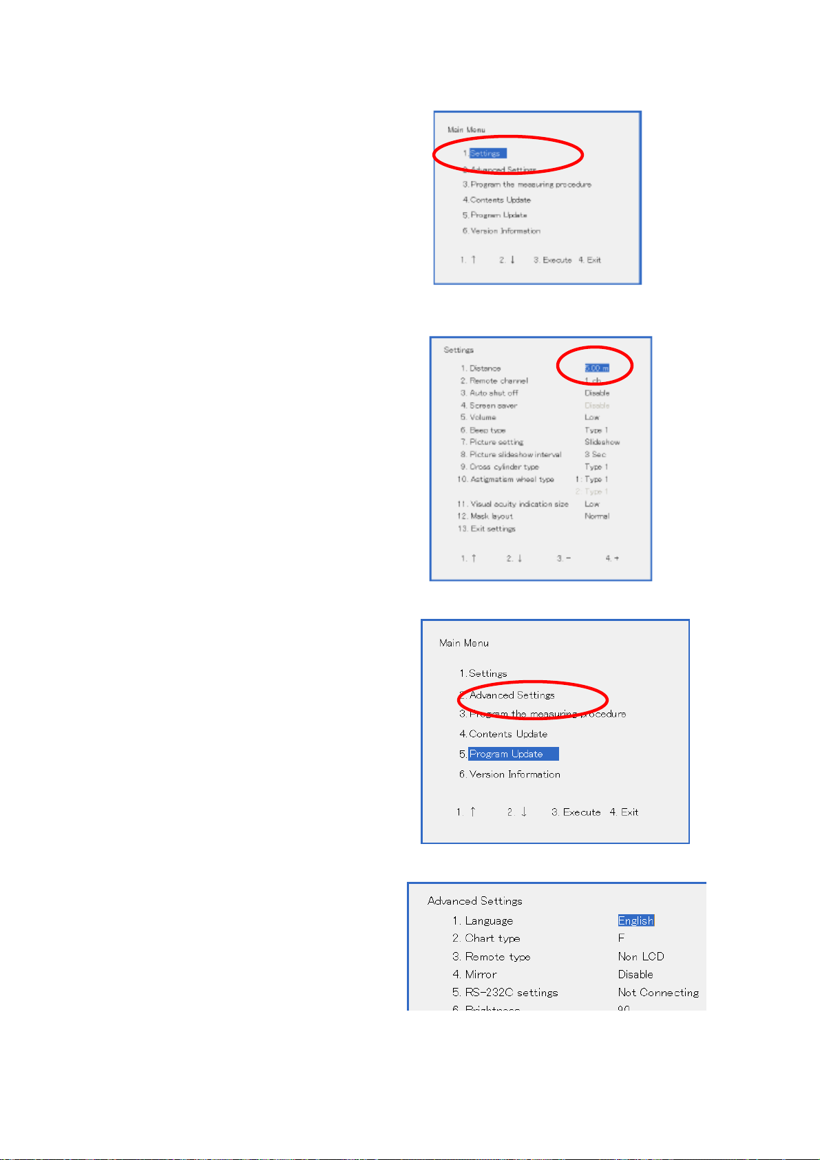
(3)[1. Settings]
(4) Set the distance.
(5)Exit and go to [2.select Advanced Settings].
(6)Select each necessary item.
24
Page 26

1. Language (not necessary to change)
Selectable from “Japanese” and “English”. Default is “English”.
2. Chart type
Select chart type from “A” “B” “F” “H1”. Default is “F”. this must be the same with the selected chart in CV
system..
3. Remote type
Select type of controller from “Non LCD” “LCD” “KB-50”.
If setting is different in PC-50 and controller, it looks working normal but some of function might not work.
Select “KB-50” in case of using IR emitter with KB-50S/CV-5000S (SETUP 1/2/3).
Non LCD This will be used when Remote Controller of PC-50 is used.
KB-50
4. Mirror (not necessary to change)
Enable or Disable, along the case using mirrored system.
5. RS-232C settings
In case using RS-232C cable, please select “2400bps”.
Not Connecting IR emitter or remote controller is used.
2400bps For wired connection with CV-5000S/CV-5000.
9600bps
(7) Exit the menu.
25
Page 27

5-5. PC-50 /CC-100 series /ACP-8 / MC-3 (IR emitter)
Please see instruction manual for how to set up ACP-8/MC-3/PC-50.
5-5.1. Cabling
Connect IR emitter to IR port of power supply.
IR emittor 424120005
(SETUP 1/2)
(SETUP3)
26
Page 28

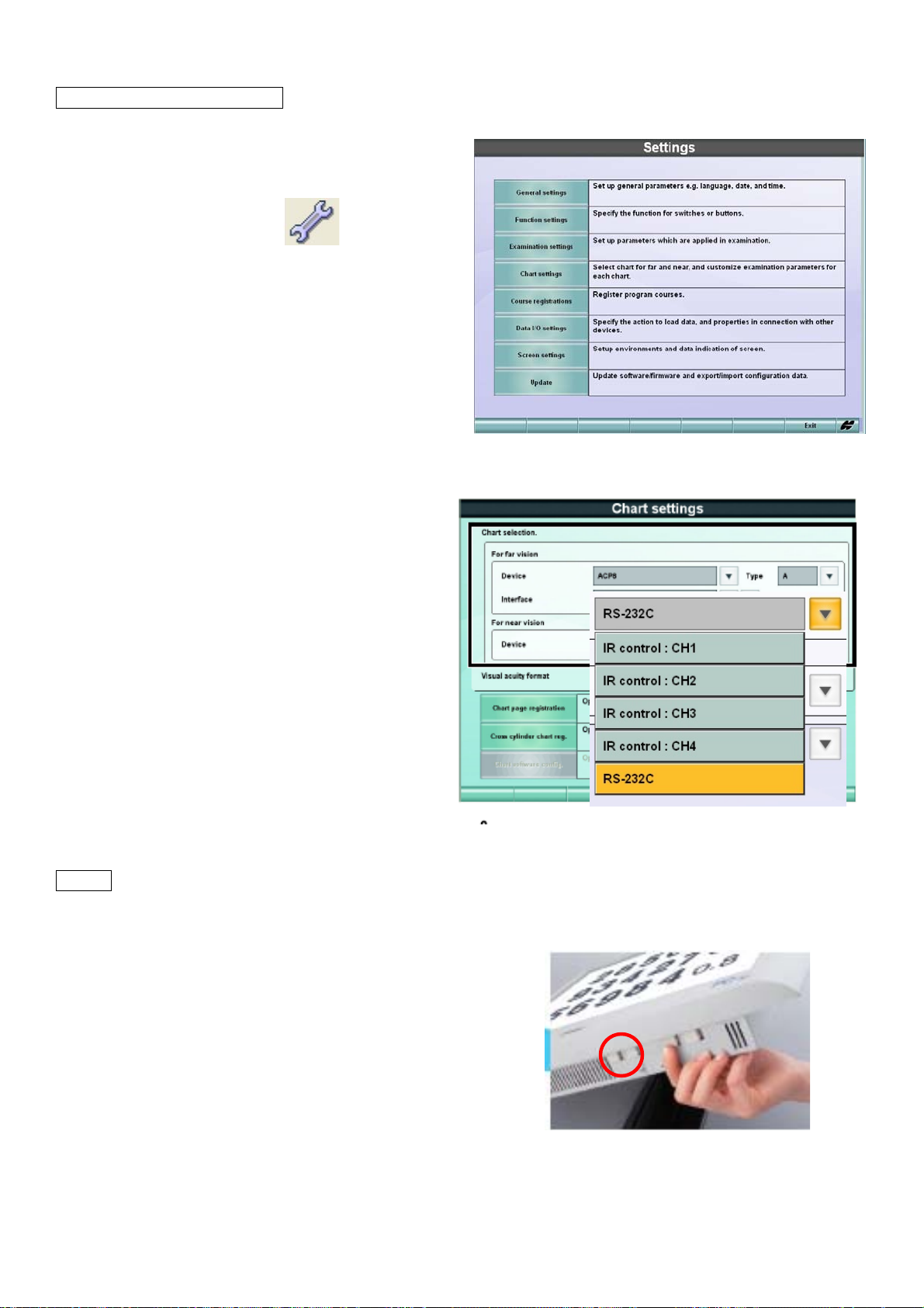
5-5.2. Settings in CV-5000S
(1) (SETUP1) press [Shift]&[Menu], and
select [Settings]_[Chart Settings]
(SETUP2,3) click [Settings ]
select [Chart Settings]
(2) Select each item.
Device : ACP or MC-3 or PC-50
Type : A, B, F, H
Interface : IR control CH1-CH4.
and
z When “IR control” is selected in [Interface],
appears on the right side.
Click this and check whether the IR signal and chart device are synchronized via the selected
channel.
5-5.3. In case of PC-50.
See 5-4.3
27
Page 29

6. Connection with refraction instruments
CL(Rx)
STD1 format
Xml format
9 Data from refraction units are transferred in STD1 format by serial communication and saved in xml format
9 KR-1, furthermore, is capable of transferring data directly in xml format by LAN network.
9 Only representative value of Ref / Kerato data are saved.
inside shared folder or default folder of CV-5000S system.
data
Ref (AR)
data
Control box SETUP1/2 has 3 ports for serial data transfer communication.
COM2 Æ
COM1 Æ
Dsub 9 pins male
SETUP 3 has no port for refraction unit, connect the unit directly to PC.
Å COM3
Din8 female
28
Page 30

General information about cables
418120002 RS-232C 5m
(DIN 8 pins male L-shape – D SUB 9 pins female)
424290061 RS-232C 10m
(DIN 8 pins male L-shape – D SUB 9 pins female)
432140006 RS-232C 5m
(DIN 8 pins male L – DIN 8 pins male L)
432140010 RS-232C 10m
(DIN 8 pins male L – DIN 8 pins male L)
RS232C-USB converter cable
(D SUB 9 pins male – USB (A))
Please arrange locally if necessary.
LAN cable (cat 5 / 5e / 6, straight)
Please arrange locally.
6-1. RM/KR-8900 (RS-232C)
6-1.1. RM/KR setting
(1) Power up RM/KR-8900 with holding the menu button
to enter [INITIAL MENU].
(2) Select [ON-LINE]_[DATA FORMAT]_[STD1]
29
Page 31

(3) Select [ON-LINE]_[BAUD-RATE]_[9600].
Select [EXIT] to confirm and close.
*in case of KR-8900,
select [ON-LINE]_[OUTPUT DATA TYPE]_[ALL].
(4) Reboot RM/KR-8900 and press the control lever switch.
Then press menu button to enter [SETTING MENU].
(5) Select [OUTPUT DATA]_[YES].
Then select EXIT to confirm and close.
6-1.2. Cabling between RM/KR-8900 and CV power supply box.
1. 418120002 (RM out port to CV COM1/2)
(RM out port to PC)
2. 432140006 (RM to CV COM3)
30
Page 32

6-1.3. CV-5000S setting
(1) (Setup 1) Press [Shift] & [Menu] button to access the setting screen.
(Setup 2,3) Click [Settings]
icon.
(2) Select [Data I/O settings]_[System Configurations]
(3) Select [LAN configuration]
(4) Tick off in “Enable network connection”.
31
Page 33

(5) Select [Serial configuration] .
(6) In the blank connection, touch the [▼] button
and select each as follows;
for : [In] AR/Rx data receive
Port No. : COM port number RM/KR is connected.
Baud Rate : 9600
(identical with the baud rate of machine)
To connect the NIDEK refractometer (model: older than 530A),
To connect the NIDEK refractometer (model: 530A and later), select “[In] REF data receive (01)”.
select “[In] REF data receive (00)”.
(7) touch [OK]
6-1.4. Check data transfer RM/KR-8900 Æ CV-5000S
(1) measure objective data in RM/KR-8900
(2) Press [print] button
(3) Check “RS-232C SUCCESS” on the screen.
(4) Press [IN] button on KB-50S.
Click [Data Import] on monitor.
(5) Check the measured power was actually
received.
32
Page 34

6-2. KR-1 (RS-232C)
6-2.1. KR-1 setting.
(1) Power on KR-1.
(2) Select [Menu]_[Comm]_[Output data]_[All]
Select [Menu]_[Comm]_[STD1]
Select [Menu]_[Baud Rate]_[9600].
6-2.2. Cabling between KR-1 & CV-5000S
1.418120002 (KR out port to CV COM1/2)
(KR out port to PC)
2. 432140006 (KR OUT to CV COM3)
6-2.3. CV-5000S setting
See 6-1.3
6-2.4. Check data transfer KR-1 Æ CV-5000S
(1) measure objective data in KR-1
(2) Press [print] button
(3) Check “RS-232C SUCCESS” on the screen
(4) Press [IN] button on KB-50S
Click [Data Import] on monitor.
(5) Check the measured power was actually
received.
z If patient ID is input on KR-1, ID will be transferred
and shown in Patient ID column.
33
Page 35

6-3. KR-1 (LAN)
6-3.1. Settings in KR-1
(1) Power up KR-1 and select [Menu]_[LAN]
(2) set each item as follows.
LAN connection ON
XML file output ON
Ref / Kerato data output OFF
Shared folder configuration
¥¥IP address of shared CV
system¥RM
e.g. ¥¥192.168.128.152¥rm
• Shared folder
Default “TOPCON”
Or user name which is otherwise assigned to access shared
• User name
folder.
*please do not tell this information to the customer
Default “CV-5000S” (all capital)
Or password which is otherwise assigned to access the shared
• Password
folder.
*please do not tell this information to the customer
IP properties Fix.
Assign KR-1 IP address to access network with CV-5000S
IP address
e.g. 192.168.128.153
Set the subnet mask.
Subnet mask
e.g. 255.255.255.0
Default gateway
Set the default gateway for the network if necessary.
e.g. 192.168.128.254
34
Page 36

6-3.2. Cabling
LAN (straight) left LAN port to hub or PC
6-3.3. Setting in CV-5000S
(1)
(Setup 1) Press [Shift] & [Menu] button to access the
setting screen.
(Setup 2,3) Click [Settings]
icon.
(2)Select [Data I/O settings]_[System Configurations]
35
Page 37

(3) Select [LAN configuration]
(4) Tick in “Enable network connection”
(5) Input IP properties
Input the IP address of CV system which consist network with KR-1.
IP address
e.g. 192.168.128.152
*should be identical with the one input for step 6-3.1
Set the subnet mask identical for CV system and KR-1
Subnet mask
e.g. 255.255.255.0
Set the default gateway for the network if necessary.
Default gateway
e.g. 192.168.128.254
4.’ In case of SETUP 3, IP address is retrieved automatically from the Windows network setting.
If there is not any, please input the IP address, Subnet mask, Default gateway in the following.
(Windows XP)
[Control Panels]_[Network] _ [Local Area Connection] _[properties]
(Windows7)
[Control Panels] – [Network and Internet] – [Networks and Sharing Center]
– [Local Area Connection]
36
Page 38

IP address should be identical with the one input for step 6-3.1
(6) Touch [Data folder]
(7) Tick in “Use shared folder in CV system” of [ AR data folder configuration]
KR-1 data is saved in pre-installed folder of
CV-5000S system.
*With tick in [Use shared folder in CV system], you
only need to input IP address of CV-5000S
system. Preinstalled folder will be used and
default authentication ID will be active for
accessing the shared folder.
(ID : TOPCON,
Password : CV-5000S)
(8) Input the IP address of CV system which has shared folder
*This must be identical among all networked units.
e.g. ¥¥192.168.128.152
(9) Touch [OK]
.
6-3.4. Check data transfer KR-1 Æ CV-5000S
1. Measure data with KR-1
2. Touch Print icon.
3. Press [IN] on KB-50
Click [Data Import]
on monitor.
4. Make sure the data coming in AR data.
* If patient ID is input on KR-1,
it will be transferred and shown in
Patient ID column.
37
Page 39

6-4. TRK-1P (RS-232C)
6-4.1. Settings in TRK-1P
(1) Power up TRK-1P with holding 2nd button from the right
to enter [INITIAL MENU].
(2) select [INITIAL MENU[_[ON-LINE]
Select [ON-LINE]_[OUTPUT DATA TYPE]_[R/K].
Select [ON-LINE]_[DATA FORM]_[STD1]
Select [ON-LINE]_[DATA OUTPUT PORT]_
[RS-232C]
38
Page 40

Select [ON-LINE]_[BAUD RATE]_[9600]
6-4.2. Cabling between TRK-1P and CV-5000S
418120002 (RM out port to CV COM1/2)
432140006 (RM to CV COM3)
6-4.3. Settings in CV-5000S
See 6-1.3
6-4.4. Check data transfer TRK-1P Æ CV-5000S
1. measure data with TRK-1P
2. Press print
3. Press [IN] on KB-50S.
Click [Data Import]
on monitor.
5. Make sure the data coming in AR Data area.
6-5. CL-200 (RS-232C)
6-5.1. Settings in CL-200
(1) With pressing 2nd right button and power up CL-200
(2) [INITIAL MENU] opens and make sure
[RS232C]_[NORMAL]
39
Page 41

(3) [EXIT]
(4) On measurement screen, press [MODE], and press [MENU].
(5) Select [MENU]_[RS232C]_[STD1]
(6) Select [MENU]_[SEQ], and put identification number on CL-200
6-5.2. Cabling between CL-200 and CV-5000S
418120002 (CL OUT port to CV COM1/2, or PC)
432140006 (CL OUT port to CV COM3)
40
Page 42

6-5.3. Settings in CV-5000S
(1) (Setup 1) Press [Shift] & [Menu] button to access the setting screen.
(Setup 2,3) Click [Settings]
icon.
(2)Select [Data I/O settings]_[System Configurations]
(3) Select [LAN configuration]
(4) Tick off in “Enable network connection”.
41
Page 43

(5) Select [Serial configuration] .
(6) In the blank connection, select as follows;
For : [In] AR/Rx data receive
Port No. : COM port number CL is connected.
Baud Rate : 2400 (fixed)
*To connect the NIDEK lens meter, select “[In] LensMeter data receive”.
(7) Touch OK
6-5.4. Check data transfer CL-200Æ CV-5000S
(1) Measure eyeglasses or lens with CL-200.
(2) When it comes to “PRINT OK”,
(3) Press [print]
(4) Press [IN] switch on KB-50
Click [Data Import]
on monitor.
(5) Make sure the CL-200 data is coming into
Rx Data list.
6-6. EZ-200 (RS-232C)
6-6.1. Settings in EZ-200
(1) Power up EZ-200.
(2) Press [Mode], and [Menu]
42
Page 44

(3) Select [MENU]_[RS-232C]_[OUTPUT]
Then select [EXIT] to confirm
(4) Press [Mode] and [Menu]
(5) Select [MENU]_[RS-FORMAT]_[STD1]
Then select [EXIT] to confirm
6-6.2. Cabling between EZ-200 and CV-5000S
418120002 (EZ out port to CV COM1/2, PC)
432140006 (EZ out porty to CV COM3)
6-6.3. Settings in CV-5000S
See 6-5.3
6-6.4. Check data transfer EZ-200 Æ CV-5000S
(1) Measure eyeglasses with EZ-200
(2) After getting the reading press[Print]
(3) Press [IN] switch on KB-50
Click [Data Import]
on monitor.
(4) Make sure the reading is set in Rx Data area.
43
Page 45

7. Output subjective data to PC
General information about cables
418120002 RS-232C 5m
(DIN 8 pins male L-shape – D SUB 9 pins female)
424290061 RS-232C 10m
(DIN 8 pins male L-shape – D SUB 9 pins female)
RS-232C cross
(D SUB 9 pins female - D SUB 9 pins female)
Please arrange locally
RS-232C-USB converter cable (D SUB 9 pins
male – USB (A))
Please arrange locally if necessary
LAN cable (cat 5 /5e/ 6 straight)
7-1. IMAGEnetR4
STD1 format
RS232C cable
MDR
44
Page 46

7-1.1. Cabling between CV-5000S and PC
418120002 (CV COM3 to PC serial)
D SUB-DSUB (cross) (CV COM1/2 to PC serial)
7-1.2. Settings in CV-5000S
(1) (Setup 1) Press [Shift] & [Menu] button to access the setting screen.
(Setup 2,3) Click [Settings]
icon.
(2)Select [Data I/O settings]_[System Configurations]
(3) Select [LAN configuration]
(3) Tick off in “Enable network connection”.
45
Page 47

(4) Select [Serial configuration] .
(5) Select one of blank connection and set as follows.
*for : [I/O] Database connection
*Port No. : COM1-3 which is connected to IMAGEnetPC
*Baud Rate : 2400 bps (fixed)
(6) Click OK
(7) (SETUP1) Go to [Function Settings]_[Print Switch]_Action,
Please select [Data export] or [Printout & data export]
(8) Touch OK
7-1.3. IMAGEnetR4 and MDR
(1)Install Prerequisites
*Prerequisites must be Ver.4.0.
(2)Install IMAGEnet
* IMAGEnet R4 must be later than Ver.4.13.
(3)Install “Multi Data Receiver” (MDR).
46
Page 48

7-1.4. Settings in MDR
(1)Required file
CV5000-STD1-InPlugin.dll Interface file for receiving CV-5000 (RS-232C) data
Please find the above file in C¥Program Files¥TOPCON¥MDR¥Plugin.
If it does not exist, please copy and paste.
(2) Start [Multi Data Receiver Configuration] ([MdrSetup.exe],
File Detail
(3) [CV-5000 STD1 Plugin] shall be listed in [Communication Plug-in] window.
(4) Select [CV-5000 STD1 Plugin]
(5) Click [Settings]
47
Page 49

(6) in [Setup] dialog, input [COM PORT] and click [OK]
* Select [COM Port] in the pulldown list.
(7)
Select [ExamData Plugin]
(8) Click [Setting]
(9) in [General] tab, input [Database] information.
48
Page 50

(10) in [Out plugin], tick in [Show Register Window].
* Please see “MDR setup manual” for detail.
7-1.5. check data transfer CV-5000S Æ IMAGEnetR4
(1) Check MDR is at waiting-status, and pop-up
window in open.
(2) Measure with CV-5000S
(3) (SETUP1) Press Print switch
(SETUP2) Click [Data Export]
icon. (*register this icon on tool bar)
49
Page 51

(4) See MDR windows received data.
(date & time only)
(5) Register with patient ID
(6) Open with IMAGEnetR4.
50
Page 52

7-2. I-base
7-3. XML format
.xml file export will be available in next version.
Only LAN connection realizes .xml format export.
7-3.1. Connect LAN cable to PC (SETUP3) or control box (SETUP1/2) at always left side port.
7-3.2. Format can be selectable among “.xml file”, “export file Ver.1.00” and “export file ver.2.14”.
7-3.3. Settings as follows.
1.[Settings]_[Data IO settlings]_[System configurations]_[Data file configurations]
2.Select “File Format Version”.
3.Tick in “Use pre-installed shared folder” if using the shared folder in CV-5000S system.
If using shared folder at other path, input the shared folder IP for the exported file
51
Page 53

8. Network system 1
To add a new CV-5000S (SETUP 1/2/3) to existing CV-5000 system and RM/CL
8-1. Data flow
¾ RM/KR/CL data will be sent to CV-5000/CV-5000S in STD1 format.
¾ CV-5000 and CV-5000S received same data list sent via RM/KR/CL.
¾ If RM/KR/CL has patient ID capability, patient ID will be sent to CV-5000 as well.
¾ Subjective data will not be saved.
¾ Shared folder setting is not required. In case of one, non-networked CV-5000S is used, data folder
inside CV-5000S is automatically used.
¾ It is possible to set the period to delete and refresh the RM/CL data saved in shared folder.
CV-5000 (1)
CV-5000S (2)
Shared
folder (AR)
8-2. Cabling
(1)
RS-232C
(3)
RS-232C
CV-5000S (3)
Shared
folder (Rx)
(2)
RS-232C
(4)
RS-232C
Shared
folder (AR)
Shared
folder (Rx)
CV-5000 (4)
(1) 432140005 DIN8 DIN8 (RM/CL to CV RM )
(2) 418120002 Din8-DSUB9(CV COM to CV COM1/2)
432140005 DIN8 DIN8 (CV COM to CV COM3) * cannot be used for SETUP3
(3) 432140005 DIN8 DIN8 (RM/CL to CV COM3 )
418120002 Din8-DSUB9 (RM/CL to CV COM1/2)
(4) 432140005 DIN8 DIN8 (CV COM3 to CV RM)
418120002 Din8-DSUB9(CV COM1/2 to CV RM)
52
Page 54

8-3. Settings
8-3.1. RM/KR/CL Æ (STD1).
Please see RM/KR(6-1.1), KR-1(6-2.1),TRK-1P(6-4.1), CL-200(6-5.1), EZ-200(6-6.1).
8-3.2. RM/KR Æ CV-5000 (1) Æ CV-5000S (2)
CV-5000(1) Set the dipswitch of power supply box as below.
DIP switch 1. 1 OFF
DIP switch 1. 2 ON
DIP switch 1. 3 OFF
DIP switch 1. 4 ON (9600)
*OFF (2400) to CV to RM/KR
DIP switch 2 1 ON
DIP switch 2 2 ON
DIP switch 2 5 OFF
DIP switch 2 6 OFF
For the other connection, please see the CV-5000 DIP/SW setting manual.
8-3.3. CV-5000(1)Æ CV-5000S(2)
(1)(SETUP1) Press the [Shift] and [Menu]
(SETUP2,3) click [settings]
(2)[Data I/O settings] _ [System configurations]
icon.
(3)[Serial config.]
53
Page 55

(4)In any of blank connection, touch the [▼] button and select each item.
“for” : “[In] AR/Rx data receive”.
Port : Port number which (old) CV-5000 is connected.
BaudRate : 2400bps or 9600 bps.
(same baud rate selected for step 8-3.2)
8-3.4. RM/KR/CL ÆCV-5000S(3)Æ CV-5000(4)
1. (SETUP1) Press the [Shift] and [Menu]
(SETUP2,3) click [settings]
icon.
1. [Data I/O settings] _ [System configurations]
3. [Serial config.]
4. In any of blank connection, touch the [▼] button and select
“for” : “[In] AR/Rx data receive”.
Port : Port number which RM/KR/CL is connected.
BaudRate : 2400bps or 9600 bps.
(same baud rate set in the machine)
* In case several machines are connected,
create connection for each.
54
Page 56

3. In any of blank connection, touch the [▼] button and select each item.
“for” : “[Out] RM/CL data transfer”.
Port : Port number which (old) CV-5000 is connected.
BaudRate : 2400bps or 9600 bps.
5. Click OK
and exit the settings.
9. Network system 2
To have several CV-5000S (System 1 or 2) and CL. KR-1
9-1. Data flow
RM/KR/CL
CV-5000S(1) CV-5000S (2)
(1)
RS-232C
STD1
(2) LAN
XML
(2) LAN
XML
(2) LAN
XML
Shared Folder
Ref data
CL data
¾ Shared folder is pre-installed in CV-5000S system. In the above picture, supposing shared
folders are the one preinstalled CV-5000S(2).
¾ As far as they are networked, Ref/CL data saved in shared folder can be retrieved any time.
¾ It is possible to set the period to delete and refresh the RM/CL data saved in shared folder.
¾ Subjective data is not saved, they will be printed out or discarded. (since next version, subjective
data will be export in .xml format.
55
Page 57

¾ If patient ID is input in KR/RM, patient ID will be output together with data.
9-2. Cabling
(1) 432140005 DIN8 DIN8 (RM/CL to CV COM3 ) or
418120002 DIN8-Dsub9 Din8-DSUB9(CL to CV COM1/2)
(2) LAN
9-3. Settings
9-3.1. RM/KR/CL Æ (RS-232C setting)
They should output data in STD1 format.
Please see RM/KR(6-1.1), KR-1(6-2.1),TRK-1P(6-4.1), CL-200(6-5.1), EZ-200(6-6.1).
9-3.2. KR-1 Æ (LAN )
Please see 6-3.1.
In Menu_LAN_Sharedfolder, input IP address of CV-5000S(2)
¥¥ IP address of shared CV 5000S(2)¥rm
e.g. ¥¥ 10.140.19.112¥rm
9-3.3. RM/KR ÆCV-5000S (1) ⇔ Shared folder
1. (SETUP1) Press [Shift] and [Menu]
(SETUP2) click [settings]
icon.
2. [settings]_[Data I/O settings]_[System configuration]
3. [Serial config.]
4. In any of blank connection, touch the [▼] button and select each item.
“for” : “[In] RM/CL data receive”.
Port : Port number which RM/KR/CL is connected.
BaudRate : 2400bps or 9600 bps.
(same baud rate set in the machine)
* In case several machines are connected,
create connection for each.
56
Page 58

6. [LAN Configuration]
7. Tick in [Enable Network connection] and input IP address of CV-5000S(1)
9. [Data Folder]
10. if RM/KR is used,
Tick in [use shared folder in CV system] in AR data folder configuration.
Input IP address of CV-5000(2)
Tick in [use shared folder in CV system] in Rx data folder configuration.
Input IP address of CV-5000(2)
9-3.4. CV-5000S (2) & Shared folder
1. (SETUP1) Press [Shift] and [Menu]
(SETUP2) Click [settings]
icon.
2. [Settings]_[Data I/O settings]_[System configuration]
57
Page 59

3. [LAN Configuration]
4. Tick in [Enable Network connection] and
Input IP address of CV-5000S(2)
6. [Data Folder]
7. if RM/KR is used,
Tick in [use shared folder in CV system] in AR data folder configuration.
Input IP address of CV-5000(2)
Tick in [use shared folder in CV system] in Rx data folder configuration.
Input IP address of CV-5000(2)
8. Click OK.
58
Page 60

10. Network system 3
To have several CV-5000S (Setup 1/2 and Setup 3)
10-1. Data flow diagram
CV-5000S (1) CV-5000S (2)
9 Shared folder must be on CV-5000(1) SETUP3.
Shared folder
(AR/Rx)
(2)
(2)
LAN XML
(1)
RM/KR/CL
RS-232C
STD1
9 CV-5000S(1) must not have user account named or including “shared folder ID” (=TOPCON)
9 Shared folder must be on SETUP3
9 RM/K/CL data sent via RS-232C is once received at CV-5000S(2), then saved in shared folder.
9 KR-1 data if sent via LAN is saved directly in shared folder.
9 RM.KR.CL data are shared by CV-5000S(1) and (2).
9 Subjective data is not saved must be printout. (can be exported in file since next version)
10-2. Cabling
(1) 432140005 DIN8 DIN8 (RM/CL to CV COM3 ) or
418120002 DIN8-Dsub9 Din8-DSUB9 (CL to CV COM1/2)
(2) LAN
10-3. Settings
10-3.1. RM/KR/CL Æ RS-232C setting)
They should output data in STD1 format.
Please see RM/KR(6-1.1), KR-1(6-2.1),TRK-1P(6-4.1), CL-200(6-5.1), EZ-200(6-6.1).
59
Page 61

10-3.2. KR-1 Æ (LAN )
Please see 6-3.1.
In Menu_LAN_Sharedfolder, input IP address of CV-5000S(1)
¥¥ IP address of shared CV 5000S(1)¥rm
e.g. ¥¥ 10.140.19.112¥rm
10-3.3. CV-5000S(1)
1.Enable “Guest” account.
[My Computer]_[Control Panels]_[Administrative Tools]_[Computer Management]_
[Local Users and Groups]_[Users]_[Guests]
Righclick and select [Properties]
If “Account is disabled” is ticked, remove tick.
This is to permit the network access of another computer (=Guest).
2. Open the PC to networking access
[My Computer]_[Control Panels]_[Administrative Tools]_[Security Settings]_[Local Policies]_
[User Rights Assignment]_[Deny access to this computer from the network].
If “guest” exists, right click and select properties. Remove “Guest.
60
Page 62

3. If it is Windows 7, turn off “password protected sharing”.
[My Computer]_[Control Panels]_[Network and Sharing center]_[Advanced Sharing settings]
_[Password protected sharing].
4.
61
Page 63

10-3.4. CV-5000S(1) & Shared folder
1. Click [settings] icon.
2. [Settings]_[Data I/O settings]_[System configuration]
3. [LAN Configuration]
4. Tick in [Enable Network connection] and check IP address of CV-5000S(1)
IP address is automatically generated from Windows network setting.
See 8-3.2 5’.
6. [Data Folder]
7. if RM/KR is used,
Tick in [use shared folder in CV system] in AR data folder configuration
Input IP address of CV-5000(1)
Tick in [use shared folder in CV system] in Rx data folder configuration.
Input IP address of CV-5000(1)
8. Click OK.
62
Page 64

10-3.5. RM/KR ÆCV-5000S(2) Å Æ Shared folder
1. (SETUP1) Press [Shift] and [Menu] , (SETUP2) click [settings] icon.
2. [settings]_[Data I/O settings]_[System configuration]
3. [Serial config]
4. In any of blank connection, touch the [▼] button and select each item.
“for” : “[In] RM/CL data receive”.
Port : Port number which RM/KR/CL is connected.
BaudRate : 2400bps or 9600 bps.
* In case several machines are connected,
create connection for each.
6. [LAN Configuration]
7. Tick in “Enable Network connection” and input IP address of CV-5000S(2)
63
Page 65

9. [Data Folder]
10. if RM/KR is used,
Tick in [use shared folder in CV system] in AR data folder configuration
Input address of CV-5000(1)
Tick in [use shared folder in CV system] in Rx data folder configuration
Input IP address of CV-5000(1)
11. Click OK
11. Network system 4
System 3 & system 3
11-1. Data flow
CV-5000S(1)
Shared folder
(AR/Rx)
(2)
LAN
xml
RM/KR/CL
CV-5000S(2)
(1)
RS-232C
STD1
Practice’s network
9 Shared folder can be on network, or can be the preinstalled folder in either CV-5000S.
9 RM/K/CL data sent via RS-232C is once received at CV-5000S(2), then saved in shared folder.
9 KR-1 data if sent via LAN is saved directly in shared folder.
64
Page 66

9 RM.KR.CL data are shared by CV-5000S(1) and (2).
9 Subjective data is not saved, thus must be printout. (can be exported in file since next version)
9 CV-5000S(1) must not have user account named “TOPCON”.
9 Any of user/log in ID and password of CV-5000S(1) PC nor CV-5000S(2) PC should not include the
shared folder ID (=TOPCON)
(in September, CV-system will access to shared folder regardless of login user. )
11-2. Cabling
(1) 432140005 DIN8 DIN8 (RM/CL to CV COM3 ) or
418120002 DIN8-Dsub9 Din8-DSUB9(CL to CV COM1/2)
(2) LAN
11-3.
Settings
11-3.1.
CV-5000S (1)
1.Enable “Guest” account.
[My Computer]_[Control Panels]_[Administrative Tools]_[Computer Management]_
[Local Users and Groups]_[Users]_[Guests]
Righclick and select [Properties]
If “Account is disabled” is ticked, remove tick.
This is to permit the network access of another computer (=Guest).
5. Open the PC to networking access
[My Computer]_[Control Panels]_[Administrative Tools]_[Security Settings]_[Local Policies]_
65
Page 67

[User Rights Assignment]_[Deny access to this computer from the network].
If “guest” exists, right click and select properties. Remove “Guest.
6. If it is Windows 7, turn off “password protected sharing”.
[My Computer]_[Control Panels]_[Network and Sharing center]_[Advanced Sharing settings]
_[Password protected sharing].
7.
66
Page 68

4. Start CV-5000S PC software and Click [settings] icon.
5. [Settings]_[Data I/O settings]_[System configuration]
6. [LAN Configuration]
7. Tick in [Enable Network connection] and check IP address of CV-5000S(1)
IP address is automatically generated from Windows network setting.
See 8-3.2 5’.
6. [Data Folder]
7. if RM/KR is used,
Tick in [use shared folder in CV system] in [AR data folder configuration]
Input IP address of CV-5000(1)
Tick in [use shared folder in CV system] in Rx data folder configuration.
Input IP address of CV-5000(1)
8. Click OK.
67
Page 69

11-3.2. RM/KRÆ CV-5000(2)Å Æ Shared folder
1. Start CV-5000S PC software and click [settings] icon.
2. [Settings]_[Data I/O settings]_[System configuration]
3. [LAN Configuration]
4. Tick in [Enable Network connection] and check IP address of CV-5000S(2)
IP address is automatically generated from Windows network setting.
See 8-3.2 5’.
6. [Data Folder]
7. if RM/KR is used,
Tick in [use shared folder in CV system] in AR data folder configuration.
Input IP address of CV-5000(1)
Tick in [use shared folder in CV system] in Rx data folder configuration.
Input IP address of CV-5000(1)
8. [Serial config]
68
Page 70

9. In any of blank connection, touch the [▼] button and select each item.
“for” : “[In] RM/CL data receive”.
Port : Port number which RM/KR/CL is connected.
BaudRate : 2400bps or 9600 bps.
5. Click OK
11-3.3. RM/KR/CL Æ(RS-232C setting)
They should output data in STD1 format.
Please see RM/KR(6-1.1), KR-1(6-2.1),TRK-1P(6-4.1), CL-200(6-5.1), EZ-200(6-6.1)
11-3.4. KR-1 Æ (LAN )
Please see 6-3.1.
In Menu_LAN_Sharedfolder, input IP address of CV-5000S(1)
¥¥ IP address of shared CV 5000S(1)¥RM
e.g. ¥¥ 10.140.19.112¥rm
12. Network system 5
System 1, CL, KR, IMAGEnetR4
12-1. Data flow
RM/KR/CL
9 CV-5000S receives representative value from RM/KR/CL and send subjective data to IMAGEnetR4
(1)
RS232C
STD1
CV-5000S
RM/KR/CL
(KR-1)
(3)
RS-232C
STD4
(2)
RS-232C
STD1
69
IMAGEnetR4
database
Page 71

together with RM/KR/CL data.
9 In order to keep KR-1 all data (including peripheral kerato data), it must be linked directly with
IMAGEnetR4, via RS-232C cable and in STD4 format.
12-2. Cabling
(1) 418120002 DIN8-Dsub9 Din8-DSUB9(CL to CV COM1/2)
(2) 418120002 DIN8-Dsub9 Din8-DSUB9(CV COM3 to PC serial )
or DSUB DSUB (cross) locally arrange (CVCOM1/2 to PC serial)
(3) 418120002 DIN8-Dsub9 Din8-DSUB9(CV COM3 to PC serial )
Serial –USB conversion cable is recommended.
12-3. setting
12-3.1. RM/KR/CL Æ (RS-232C)
They should output data in STD1 format. (KR-1 can be STD4)
Please see RM/KR(6-1.1), KR-1(6-2.1),TRK-1P(6-4.1), CL-200(6-5.1), EZ-200(6-6.1)
12-3.2. RM/KR/CL ÆCV-5000SÆIMAGEnetR4
1. (SETUP1) Press [Shift] and [Menu] , (SETUP2) click [settings] icon.
2. [settings]_[Data I/O settings]_[System configuration]
3. [Serial config]
4. In any of blank connection, touch the [▼] button and select each item.
“for” : “[In] RM/CL data receive”.
Port : Port number which RM/KR/CL is connected.
BaudRate : 2400bps or 9600 bps.
70
Page 72

5. Select one of blank connection and set as follows.
*for : [I/O] Database connection
*Port No. : COM1-3 which is connected to IMAGEnetPC
*Baud Rate : 2400 bps
6. [LAN Configuration]
7. Tick off in [Enable network connection]
10.Click OK
11.(SETUP1) Go to [Function Settings]_[Print Switch]_Action,
Please select [Data export] or [Printout & data export]
71
Page 73

12.Touch OK
12-3.3. IMAGEnetR4
1.create CV-5000 communication plug-in
See. 7-1.3,7-1.4.
2. create KR-1 communication plug-in
*Communication Plug-in*
Select “KR-1 STD4 Plugin”
Select COM NO. COMPort No. which KR-1 is connected。
Select Baud Rate : 2400/9600 (identical with the machine setting)
Select Flow Control : RTS/CTS
*Out Plugi-in*
Same as CV-5000S
13. Network system 6
To have central server, IMAGEnet station, CV-5000S/KR-1
13-1. DA TA FLOW
RM/KR/CL
(KR-1)
(1) LAN
RM XML
CV-5000S(1)
(1) LAN
XML (RM/CL)
(2) RS232C
STD1
RM/KR/CL
IMAGEnetR4
database
CV-5000S(2)
(1) LAN
XML (RM/CL)
(1) LAN
Images to IMAGEnet
IMAGEnet(1)
(2) RS232C
STD1
CV data to MDR
(1) LAN
CV data (to IMAGEnet)
Shared folder
RM/CL
IMAGEnet(2)
Fundus images etc
72
Page 74

9 KR-1 data will be saved in shared folder and not directly saved in IMAGEnet.
9 CL-200 data will be saved in shared folder and not directly saved in IMAGEnet.
9 CV-5000(1) retrieves any RM/CL data from shared folder, and its subjective data is not saved.
9 CV-5000(2) retrieves any RM/CL saved in shared folder and sends subjective data to IMAGEnet (1).
9 Subject data (STD1 format) contains RM/CL data, and subjective data, and can be reviewed on
IMAGEnetR4.
13-2. Cabling
(1) LAN
(2) 418120002 DIN8-Dsub9 Din8-DSUB9 (CL OUT – CV COM1/2)
432140005 DIN8 DIN8 (RM/CL to CV COM3 )
(3) 418120002 DIN8-Dsub9 Din8-DSUB9 (CV COM3 –PC serial)
DSUB DSUB (cross) locally arrange (CVCOM1/2 to PC serial)
13-3. Settings
13-3.1. Server
1. Check IP address of server.
2. Create shared folder in server for RM/CL data (e.g. “rm” folder, “cl” folder).
13-3.2. RM/KR/CLÆ CV-5000(1)
They should output data in STD1 format.
Please see RM/KR(6-1.1), KR-1(6-2.1),TRK-1P(6-4.1), CL-200(6-5.1), EZ-200(6-6.1).
13-3.3. KR-1 Æ shared folder
1. Please see 6-3.1
2. Input IP address of server.
Shared folder configuration
¥¥ server IP address (shared folder)¥rm
• Shared folder
e.g. ¥¥192.168.128.152¥rm
• User name
• Password
(must be the identical name of created folder in 13-3.1)
user name which is permitted to access shared folder.
*please do not tell this information to the customer
*Be sure to no login user ID does not contain this user name.
password which can access the shared folder.
*please do not tell this information to the customer
73
Page 75

13-3.4. RM/KR/CL ÆCV-5000S (1) Å Æ shared folder
1. Press [Shit] & [Menu]. Click [settings] icon.
2. [Settings]_[Data I/O settings]_[System configuration]
3. [LAN Configuration]
4. Tick in [Enable Network connection]
and check IP address of CV-5000S(1)
6. [Data Folder]
7. if RM/KR is used,
Tick off [use shared folder in CV system] in AR data folder configuration.
*Input IP address of server¥rm
(must be the identical name and path of created folder in 13-3.1)
*Input user name which is permitted to access this shared folder.
*Input password assigned to the above user name.
Tick off [use shared folder in CV system]
in Rx data folder configuration.
Likewise
*Input IP address of server¥cl
(must be the identical name and path of created
folder in 13-3.1)
*Input user name which is permitted to access this
shared folder.
*Input password assigned to the above user
name.
74
Page 76

8. [settings]_[Data I/O settings]_[System configuration]
9. [Serial config]
10. In any of blank connection, touch the [▼] button and select each item.
“for” : “[In] RM/CL data receive”.
Port : Port number which RM/KR/CL is connected.
BaudRate : 2400bps or 9600 bps.
13-3.5. Shared folder ÆCV-5000S (2)Æ IMAGEnetR4
1. Press [Shit] & [Menu]. Click [settings] icon.
2. [Settings]_[Data I/O settings]_[System configuration]
3. [LAN Configuration]
4. Tick in [Enable Network connection] and
check IP address of CV-5000S(1)
75
Page 77

5. [Data Folder]
6. if RM/KR is used,
Tick off [use shared folder in CV system] in AR data folder configuration.
*Input IP address of server¥rm
(must be the identical name and path of created folder in 13-3.1)
*Input user name which is permitted to access this shared folder.
*Input password assigned to the above user name.
Tick in [use shared folder in CV system]
in Rx data folder configuration.
*Input IP address of server¥cl
*Input user name
*Input password.
7. Select [Serial configuration]
.
8.Select one of blank connection and set as follows.
*for : [I/O] Database connection
*Port No. : COM1-3 which is connected to IMAGEnetPC
*Baud Rate : 2400 bps
9.Click OK
76
Page 78

10.(SETUP1) Go to [Function Settings]_[Print Switch]_Action,
Please select [Data export] or [Printout & data export]
(11) Touch OK
13-3.6. CV-5000(S) ÆIMAGEnet (1)
Please see 7-1.3,7-1.4.
13-3.7. IMAGEnet (2)
Set up IMAGEnet R4 as required.
14. Details of setting menu
Please see instruction manual.
77
Page 79

15. Customizing pictures and movies (PC-50S only)
PC-50S enables to add still images, still images for slideshow and movies that are provided by the
user.
[Capability]
z Maximum 20 (JPG) of both still images and still images for slideshow.
z Maximum 20 (BMP) still images, which are displayed on KB-50S.
z Maximum 2 (WMV) movies.
[File format and filename requirements]
The format of the still image file and movie file is restricted as mentioned below.
Vertical/
Kind Type
horizontal
size
Still
image
Slideshow JPE
JPE
G
G
Optional
Optional
Filenam
e
01.jpg -
20.jpg
01.jpg -
20.jpg
Others
Ref/CL data
Displayed in the largest size as the
ratio of vertical and horizontal size is
kept.
Displayed in the largest size as the
ratio of vertical and horizontal size is
kept.
The video type must be the WMV
encoded by CODEC Windows
Media Video 7 - 9.
Bit rate is max. 10Mbps and frame
rate is max. 30fps.
Movie WMV
Max.
1280×1024
01.wmv
-
02.wmv
To play back a movie smoothly,
KB-50S must be connected to
PC-50S through DVI cable.
In the CV system of the personal
computer type, sometimes the
playback of movie is not smooth due
to the specification of the used
personal computer.
The filename number must be the
same as the filename number of the
still image to which this still image
for KB-50S is related.
Remarks:
This function is provided for the
following purpose: the user can
Still
image for
KB-50S
BMP
Fixed at
800×600.
01.bmp
-
20.bmp
check the far and near visions that
are as similar to those in the real
world as possible by using still
images together with PC-50S. So,
the still image for near vision must
be displayed in almost the real-thing
size.
For this reason, this function is
invalid in the CV system of the
mouse type/personal computer type
where the monitor size is not fixed.
[How to register]
Carry out registration as mentioned below.
78
Page 80

1. Make folders under USB memory in the following configuration and save the files in the
folders.
Folder Explanation
PC50S_UC Make this folder under the USB memory. This folder
will contain all the folders.
Movie Make this folder under the “PC50S_UC” folder. Save
the movie file in this folder.
Still Make this folder under the “PC50S_UC” folder. This
folder will contain the still images.
KB50S Make this folder under the “Still” folder. The BMP
images are displayed on KB-50S for the still images
displayed on PC-50S. Save the file of these BMP
images in this folder.
Selective Make this folder under the “Still” folder. Save the file of
the JPEG images to be displayed on slideshow in this
folder.
Slide Make this folder under the “Still” folder. Save the file of
the JPEG still images to be displayed on PC-50S in this
folder.
2. Connect the USB memory, which has been arranged in Step 1, to the CV system. Then,
start the CV system.
Still images and movies are not captured into the system but are read directly from the USB
memory. So it is necessary to connect the USB memory to the CV system when using this
added function.
3. Press the [Shift] and [Menu] switches to access the setting screen. Select “Chart settings”
and then “Chart Page registration”.
79
Page 81

4. Register the icons to access still image, slideshow and movie into the chart page from the
chart icon list according to the files saved in the USB memory.
Icon Explanation
These icons are used to access the still images saved
in the “Selective” folder. The number on each icon
~
corresponds to the number in the filename.
This icon is used to display the still images in the
“Slide” folder in turn as slideshow.
These icons are used to access the movies saved in
the “Movie” folder. The number on each icon
~
corresponds to the number in the filename.
5. After finishing the above registration, return to the test screen and check if the playback of
the still images, slideshow and movies is performed.
Addition of the binocular function test chart with black background
You can select the binocular function test charts with black background, which are shown below, in
each type of PC-50S.
A
B(F)/(M)
D3
D5
F
H1
To use these charts, press the [Shift] and [Menu] switches to access the setting screen.
Select “Chart settings” and then “Chart Page registration”. Register the above charts in the chart
list to the chart page.
16. Export and import settings with USB memory
Output of setting
Perform the following operations on the CV system where the setting should be output.
1. Press the [Shift] and [Menu] switches to access the setting screen.
2. Touch the [Update] button.
3. Touch the [Config. copy] button among the function buttons.
4. Connect the USB memory to the CV system.
The [Export configurations] button will be flickering. Please wait utill “Export configuration” button is
lighting without flickering.
Touch this button.
80
Page 82

The output is finished.
If you move or delete the output file out of the USB memory, the setting data cannot be re-input our
uploaded through this USB memory. Be careful.
Input of setting
Perform the following operations on the CV system where the setting should be input.
1. Press the [Shift] and [Menu] switches to access the setting screen.
2. Touch the [Update] button.
3. Touch the [Config. copy] button among the function buttons.
4. Connect the USB memory saving the setting data of the CV system, and the [Import configurations]
will be flickering. Please wait until [Import configurations] button is lighting without flickering.
Touch this button.
5. To make the setting valid, restart the CV system.
The input of setting is finished.
The setting items shown below are not copied. Be careful.
• Date setting
• Time setting
• Next data number
• Far point vision – Device
• Far point vision – Type
• Far point vision - Interface/Chart monitor selection
• Near chart – Device
• Near chart – Type
• IP properties
• Serial configuration - Connection 1
• Serial configuration - Connection 2
• Serial configuration - Connection 3
•
Serial configuration – Connection 4
17. Update KB-50S
1. Using the universal personal computer, prepare the install USB memory.
Copy installers from the install CD to the USB memory.
The install CD has “Main Installer_E” folder and “Main Installer_J” folder. “Main Installer_E”
contains the install set for export and “Main Installer_J” contains the install set for Japan.
Open the proper folder. From it, copy the “CV5000_Updater” folder to the route of USB memory.
2. On the KB-50S where you want to perform updating, press the [Shift] and [Menu] switches to access
the setting screen.
3. Touch the [Update] button.
4. Connect the install USB memory to the CV system, and the [Start] button is valid. Touch this
button.
5. Two or more installers are activated in order. Press the [OK] button for each of them to perform
update.
81
Page 83

6. When update for all the installers is finished, the message instructing to restart the system is
displayed. Check that this message is displayed and then restart the system.
End
82
 Loading...