


 Loading...
INSTALLATION MANUAL
VX-2000 series |
|
PILOT TONE DETECTION MODULE |
VX-200SP-2 |
IMPEDANCE DETECTION MODULE |
VX-200SZ-2 |
Thank you for purchasing TOA’s VX-2000 series plug-in modules.
Please carefully follow the instructions in this manual to ensure long, trouble-free use of your equipment.
TABLE OF CONTENTS |
|
1. General Description ........................................................................... |
3 |
2. HANDLING PRECAUTIONS ....................................................................... |
3 |
3. Maximum System Example ............................................................... |
4 |
3.1. Block Diagram ........................................................................................................ |
4 |
3.2. Maximum System Configuration Table .................................................................. |
5 |
4. NOMENCLATURE AND FUNCTIONS ................................................. |
6 |
4.1. Pilot Tone Detection Module VX-200SP-2 ............................................................ |
6 |
4.2. Impedance Detection Module VX-200SZ-2 .......................................................... |
7 |
5. SPEAKER LINE FAILURE DETECTION METHODS .................. |
9 |
5.1. Pilot Tone Detection Method .................................................................................. |
9 |
5.2. Impedance Detection Method ............................................................................. |
10 |
6. INSTALLATIOn ................................................................................................. |
11 |
6.1. Changing the VX-200SZ-2's ATT CTRL Output to Photocoupler Type ................ |
11 |
6.2. Installing the VX-200SE in the VX-200SZ-2 and VX-200SP-2 ............................ |
12 |
6.3. Installing Modules (VX-200SZ-2, VX-200SP-2) in the VX-2000SF Frame .......... |
13 |
7. CONNECTIONS ................................................................................................ |
14 |
7.1. VX-200SP-2 and VX-200SZ-2 Connection to Power Amplifier and Speakers ..... |
14 |
7.2. VX-200SP-2 Connection to External Attenuator .................................................. |
16 |
7.3. VX-200SZ-2 Connection to External Attenuator .................................................. |
16 |
8. LIST OF CONNECTION cableS ......................................................... |
17 |
9. cable CONNECTIONS TO RJ45 CONNECTORS ................... |
18 |
10. Monitoring Log List ......................................................................... |
19 |
11. BLOCK DIAGRAM ........................................................................................ |
20 |
11.1. Pilot Tone Detection Module VX-200SP-2 ......................................................... |
20 |
11.2. Impedance Detection Module VX-200SZ-2 ...................................................... |
21 |
12. SPECIFICATIONS ......................................................................................... |
22 |
12.1. Pilot Tone Detection Module VX-200SP-2 ........................................................ |
22 |
12.2. Impedance Detection Module VX-200SZ-2 ...................................................... |
23 |
2
1. General Description
[VX-200SP-2]
The VX-200SP-2 is an audio signal output module of the VX-2000 system with speaker line pilot tone detection. This module is to be mounted in the VX-2000SF Surveillance Frame and detects speaker line short circuits, open circuits by monitoring the terminated resistance value of the End-of-line (EOL) unit, and ground fault. Connecting the supplied EOL unit to the end of the speaker line eliminates the necessity of using the speaker line for line monitoring. However, the shielded cable must be used for speaker line.
[VX-200SZ-2]
The VX-200SZ-2 is an audio signal output module of the VX-2000 system with speaker line impedance detection. This module is to be mounted in the VX-2000SF Surveillance Frame and detects speaker line short circuits, open circuits by comparing impedance readings, and ground fault. Since the module is equipped with 2 speaker outputs (A and B), broadcasts can be maintained even if one of the two outputs fails. Failures are indicated by the LEDs on the panel.
2. HANDLING PRECAUTIONS
•Do not install the unit in locations exposed to the direct sunlight or heaters, as the unit could be deformed or discoloured.
•Avoid installing or storing the unit in dusty or humid locations, as doing otherwise could cause the unit's failure.
•Keep the unit as far away as possible from a fluorescent lamp, digital equipment, PC or other equipment which generate high frequency noise.
•Because each unit is not "hot-pluggable," the system needs to be shut down when it is installed or removed.
For turning the system power off, refer to the VX-2000 series Instruction manual.
3

3. Maximum System Example
3.1. Block Diagram
The following block diagram shows the maximum sized system that can be assembled with the VX-2000 Series.
|
|
VX-2000 |
RM-200XF + RM-210 x 10 |
|
|
|
|
VX-200XR |
RM-200X + RM-210 x 9 |
|
|
|
|
VX-200XR |
RM-200XF + RM-210 |
RM-200X + RM-210 |
|
|
|
VX-200XR |
RM-200XF + RM-210 |
RM-200X |
|
|
|
VX-200XR |
RM-200X + RM-210 |
RM-200XF |
|
|
|
VX-200XR |
PM-660U |
|
VX-200XI |
|
|
|
Cassette Player |
U-01R |
|
CD Player |
|
U-01R |
|
|
EV-200 No.1 |
|
|
EV-200 No.2 |
|
|
Chime |
|
|
Internal Timer |
|
x 16 |
Control Input x 16 |
|
x 16 |
Control Output x 16 |
*Available when the label on each packing box of the VX-2000 system components (VX-2000, VX-2000SF,
RM-200X, and RM-200XF) indicates "EN80," and the
Setting Software Version is 3.0 or later.
VX-2000SF No.1 |
VP-2421 |
SF-1 |
|
|
VP-200VX |
Standby Amplifier |
|
|
|
||
|
VP-2064 |
ZONE 1 |
|
VX-200SZ |
VP-200VX |
||
ZONE 2 |
|||
VX-200SZ |
VP-200VX |
||
ZONE 3 |
|||
VX-200SZ |
VP-200VX |
||
ZONE 4 |
|||
VX-200SZ |
VP-200VX |
||
|
|||
|
VP-2122 |
ZONE 5 |
|
VX-200SZ |
VP-200VX |
||
ZONE 6 |
|||
VX-200SP |
VP-200VX |
||
|
|||
|
VP-2241 |
ZONE 7 |
|
VX-200SP |
VP-200VX |
||
|
|||
|
VP-2122 |
ZONE 8 |
|
VX-200SP |
VP-200VX |
||
ZONE 9 |
|||
VX-200SP |
VP-200VX |
||
|
|||
|
VP-2421 |
ZONE 10 |
|
VX-200SP |
VP-200VX |
||
|
|||
VX-2000SF No.2 |
|
|
VX-2000SF No.3 |
|
|
|
VX-2000SF No.4 |
|
|
|
|
SF-8 |
* |
|
VX-2000SF No.8 * |
Standby Amplifier |
||
VP-2241 |
|
||
|
VP-200VX |
|
|
|
VP-2241 |
ZONE 71 |
|
VX-200SZ-2 |
VP-200VX |
||
|
|||
|
VP-2064 |
ZONE 72 |
|
VX-200SZ-2 |
VP-200VX |
||
|
|||
VX-200SZ-2 |
VP-200VX |
ZONE 73 |
|
|
|||
VX-200SZ-2 |
VP-200VX |
ZONE 74 |
|
|
|||
VX-200SZ-2 |
VP-200VX |
ZONE 75 |
|
|
|||
|
VP-2122 |
EOL |
|
VX-200SP-2 |
VP-200VX |
ZONE 76 |
|
EOL |
|||
VX-200SP-2 |
VP-200VX |
ZONE 77 |
|
|
|||
|
VP-2241 |
EOL |
|
VX-200SP-2 |
VP-200VX |
ZONE 78 |
|
|
|||
VX-200SI |
x 16 |
||
VX-200SO |
x 16 |
||
4
3.2. Maximum System Configuration Table
|
Component |
|
|
Maximum No. of Units |
|
|||
|
Input Source Equipment |
|
|
|
|
|
|
|
|
RM-200XF |
4 units |
|
4 units in total of |
|
8 units in total |
18 units in total of |
|
|
RM-200X |
4 units ("Emergency" type) |
|
Emergency-set models |
|
of both models |
all Input Source |
|
|
|
8 units ("General" type) |
|
|
|
|
|
Equipment |
|
Paging Microphone and Music |
8 units |
|
|
|
|
|
|
|
Sources (Cassette, CD, etc.) |
|
|
|
|
|
|
|
|
EV-200 |
2 units |
|
|
|
|
|
|
|
Chime (internal) |
1 unit |
|
|
|
|
|
|
|
RM-200XF's and RM-200X's Function Key Extension |
|
|
|
|
|
|
|
|
RM-210 |
10 units (115 function keys) per RM-200XF |
315 function keys per system |
|||||
|
|
9 units (115 function keys) per RM-200X |
|
|
|
|
||
|
VX-2000 |
|
|
|
|
|
|
|
|
VX-2000 |
1 unit |
|
|
|
|
|
|
|
Input Module (to be installed in VX-2000) |
|
|
|
|
|
|
|
|
VX-200XR |
8 units in total of all Input Modules |
|
|
|
|
||
|
VX-200XI |
Usable 900 modules: M-01F, M-01M, M-01P, M-01S, M-01T, M-03P, M-51F, |
||||||
|
900 module |
M-51S, M-51T, M-61F, M-61S, M-61T, U-01F, U-01P, |
||||||
|
|
U-01R, U-01S, U-01T, U-03R, U-03S, U-61S, and U-61T |
||||||
|
VX-2000SF |
|
|
|
|
|
|
|
|
VX-2000SF |
8 units* |
|
|
|
|
|
|
|
SF Module (to be installed in VX-2000SF) |
|
|
|
|
|
|
|
|
VX-200SP, VX-200SP-2 |
80 units |
|
80 units in total of all SF Modules |
|
|||
|
VX-200SZ, VX-200SZ-2 |
80 units |
|
(10 units per VX-2000SF) |
|
|||
|
VX-200SI |
7 units |
|
|
|
|
|
|
|
VX-200SO |
7 units |
|
|
|
|
|
|
|
Optional Equaliser Card (to be installed VX-200SP, VX-200SP-2, VX-200SZ and VX-200SZ-2) |
|
||||||
|
VX-200SE |
80 units |
|
|
|
|
|
|
|
Control Input |
|
|
|
|
|
|
|
|
VX-2000 |
16 inputs |
|
128 inputs in total |
|
|
||
|
|
(as standard equipment) |
|
|
|
|
|
|
|
VX-200SI |
112 inputs (7 units) |
|
|
|
|
|
|
|
Control Output |
|
|
|
|
|
|
|
|
VX-2000 |
16 outputs |
|
128 outputs in total |
|
|
||
|
|
(as standard equipment) |
|
|
|
|
|
|
|
VX-200SO |
112 outputs (7 units) |
|
|
|
|
|
|
|
Power Amplifier |
Note: The number and type of power amplifiers should be determined depending |
||||||
|
|
on the required speaker output for each zone. |
|
|||||
|
VP-2064 (4 ch) |
80 channels* (80 zones)* |
|
|
|
|
|
|
|
VP-2122 (2 ch) |
|
|
|
|
|
|
|
|
VP-2241 (1 ch) |
|
|
|
|
|
|
|
|
VP-2421 (1 ch) |
|
|
|
|
|
|
|
|
Standby Amplifier |
8 channels* (1 channel per VX-2000SF) |
|
|
|
|
||
|
Power Amplifier Input Module |
|
|
|
|
|
|
|
|
VP-200VX |
88 units* in total of modules installed in Power and Standby Amplifiers |
||||||
|
Power Supply |
Note: Necessary power capacity should be calculated based on total system |
||||||
|
|
specifications. |
|
|
|
|
|
|
|
VX-2000DS |
16 units* |
|
2 units per VX-2000SF |
|
|||
|
VX-200PS |
48 units* |
|
3 units per VX-2000DS |
|
|||
|
Battery |
32 or 64 units* |
|
2 or 4 units per VX-2000DS |
|
|||
* Available when the label on each packing box of the VX-2000 system components (VX-2000, VX-2000SF,
RM-200X, and RM-200XF) indicates "EN80," and the Setting Software Version is 3.0 or later.
5
4. NOMENCLATURE AND FUNCTIONS
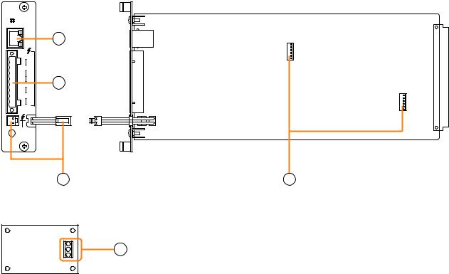
4.1. Pilot Tone Detection Module VX-200SP-2
Install this module in the VX-2000SF Surveillance Frame to detect speaker line short circuits, open circuits by monitoring the terminated resistance value of the EOL unit, and ground fault.
The pilot tone can be detected by using the supplied EOL unit in combination. Please equate this module as the VX-200SP when setting it on the PC software.
[Front] |
[Side] |
 VX-200SP-2
|
PA |
LINK |
|
MONITOR CH |
|
|
LINE |
|
ATT |
T CTRL N2 CN1 |
|
C H |
OU |
SP |
|
CH |
PA |
|
IN |
STANDBY  PA BUS
1
2
3 |
4 |
End-of-line (EOL) unit
E |
5 |
H |
|
C |
|
1.Power amplifier link connector [PA LINK]
This RJ45 connector connects to the PA LINK connector of the VP-200VX Power Amplifier Input module or the VP-3000 series Power Amplifier.
Both LEDs on this connector are not used.
2.VX-200SP plug-in screw connector
Signal lines to be connected are shown below:
•Line monitor input [LINE MONITOR]
Monitors connected speaker lines.
Connect by wiring from the SP OUT.
•External attenuator control [ATT CTRL]
Permits connection of a 3- or 4-wire system attenuator.
For the attenuator connection, refer to p. 16.
•Speaker output [SP OUT]
Connects to the speaker.
•Power amplifier input [PA IN]
Connects to the power amplifier's speaker output terminal.
3.Standby amplifier bus connector
[STANDBY PA BUS]
Connects to all outputs of a single VX-2000SF unit to be switched over to the standby amplifier when the power amplifier fails.
For details, refer to the VX-2000 series Instruction manual.
4.VX-200SE mounting connector
Used to mount the VX-200SE Equaliser Card.
5.Speaker line connection terminal
Connect the EOL unit to the end of the speaker line.
Be sure to connect the speaker's shield cable to the E terminal of EOL unit, and the other end of the cable to the equipment's functional ground of the VX-2000 system.
6
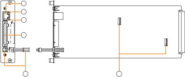
4.2. Impedance Detection Module VX-200SZ-2
Install this module in the VX-2000SF Surveillance Frame to detect speaker line short circuits, open circuits by comparing impedance readings, and ground fault.
Please equate this module with the VX-200SZ when setting it on the PC software.
Important Note
When combining this module with the VP-200VX BGM Input Module, then the signal level applied to the VP-
200VX's external input should be low, i.e. about 10 dB below the rated level. The level can also be reduced by the volume adjustment.
[Front]
VX-200SZ-2
A
PA
LINK
B
CH |
T |
SP |
|
|
OU |
|
A |
TCTRL N2CN1 |
|
|
ATT |
C H |
OU |
SP |
|
CH |
B |
PA |
|
|
IN |
[Side]
1
2
3
4
STANDBY
PA BUS
5 |
6 |
1.Power amplifier link connector [PA LINK]
This RJ45 connector connects to the PA LINK connector of the VP-200VX Power Amplifier Input module or the VP-3000 series Power Amplifier.
2.Speaker line A status indicator [A]
Shows the status of speaker line connected to the
SP OUT A terminal.
For details, refer to p. 8.
3.Speaker line B status indicator [B]
Shows the status of speaker line connected to the
SP OUT B terminal.
For details, refer to p. 8.
4.VX-200SZ plug-in screw connector
Signal lines to be connected are shown below:
•External attenuator control [ATT CTRL]
Permits connection of 4-wire system attenuators. For the connection instructions, refer to p. 15. The attenuator bypass method can be changed from relay to photocoupler type. For the modification instructions, refer to p. 11.
•Speaker outputs A and B [SP OUT A, SP OUT B]
Connect the speakers.
•Power amplifier input [PA IN]
Connects to the power amplifier's speaker output.
5.Standby amplifier bus connector
[STANDBY PA BUS]
Connects to all outputs of a single VX-2000SF unit to be switched over to the standby amplifier when the power amplifier fails.
For details, refer to the VX-2000 series Instruction manual.
6.VX-200SE mounting connector
Used to mount the VX-200SE Equaliser card.
7
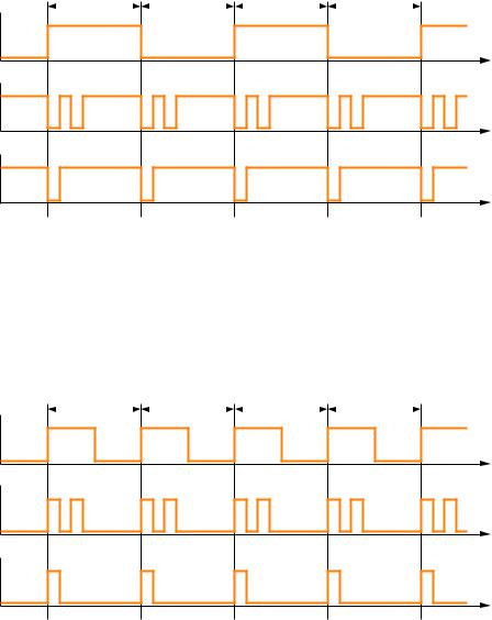
[Speaker line status vs. indicator status]
The Speaker line A or B status indicator shows the corresponding speaker line status "Normal," "Open," or "Short" by the indicator lighting conditions as follows.
•When the VX-200SZ-2 is used as factory-preset
This is the case where the initial impedance settings have not yet been performed or cannot be performed because of the speaker line failure.
(For the initial impedance settings, refer to the VX-2000 series Instruction manual.)
1 sec. |
|
1 sec. |
|
1 sec. |
|
1 sec. |
Speaker line |
ON |
Normal |
OFF |
|
|
Speaker line |
ON |
Open |
OFF |
|
|
Speaker line |
ON |
Short |
OFF |
|
Note
When either indicator shows speaker line failure (open or short), another indicator showing normal status extinguishes.
•When the VX-200SZ-2 is in normal operating mode
This is the case where the initial impedance settings have been completed.
(For the initial impedance settings, refer to the VX-2000 series Instruction manual.)
1 sec. |
|
1 sec. |
|
1 sec. |
|
1 sec. |
Speaker line |
ON |
Normal |
OFF |
|
|
Speaker line |
ON |
Open |
OFF |
|
|
Speaker line |
ON |
Short |
OFF |
|
The table below shows the speaker line A and B status (indicators status) and its log data to be displayed on a PC.
Speaker line A |
Speaker line B |
Log diaplayed on a PC |
(See the indicator status above.) |
(See the indicator status above.) |
|
Normal |
Normal |
NORMAL |
Open |
Normal |
OPEN |
Normal |
Open |
OPEN |
Short |
Normal |
OPEN* |
Normal |
Short |
OPEN* |
Open |
Open |
OPEN |
Short |
Short |
SHORT |
Open |
Short |
OPEN* |
Short |
Open |
OPEN* |
*After the VX-200SZ-2 detects line "Short" on either the speaker line A or B, the shorted speaker line will be automatically disconnected, permitting the log data to be displayed as "Open" on a PC.
8
Loading...