


OPERATING INSTRUCTIONS
PACKET INTERCOM SYSTEM
N-8000 SERIES
Thank you for purchasing TOA's Packet Intercom system.
Please carefully follow the instructions in this manual to ensure long, trouble-free use of your equipment.
TABLE OF CONTENTS
1. SAFETY PRECAUTIONS |
|
For N-8000EX/8010EX/8000RS/8010RS/8400RS/8000MI |
|
/8000DI/8000AF/8000CO/8000AL ........................................................ |
14 |
2. OPERATING INSTRUCTIONS CONFIGURATION ..................... |
16 |
Chapter 1 : GENERAL DESCRIPTION |
|
1. General Description ........................................................................ |
1-2 |
2. Features ......................................................................................................... |
1-3 |
3. HANDLING PRECAUTIONS .................................................................... |
1-3 |
4. Specifications .......................................................................................... |
1-4 |
5. System Configuration .................................................................... |
1-6 |
5.1. System Configuration Example .......................................................................... |
1-6 |
5.2. Component Description ...................................................................................... |
1-9 |
5.3. Rack Mounting Examples for Exchanges ......................................................... |
1-15 |
6. Nomenclature and functions ............................................ |
1-17 |
6.1. IP Intercom Exchanges and Their Connected Equipment ................................ |
1-17 |
6.2. IP Station .......................................................................................................... |
1-32 |
6.3. Substation Interface Units and Their Connected Equipment ........................ |
1-47 |
6.4. Interface Unit ................................................................................................... |
1-60 |
7. System Function Table ................................................................ |
1-66 |
7.1. Basic Functions ................................................................................................ |
1-66 |
7.2. Other Functions ................................................................................................ |
1-76 |
8. TWO CALL RESPONSE METHODS .............................................. |
1-78 |
8.1. Sequential Response (Master-to-Master System) ............................................ |
1-78 |
8.2. Selective Response (Master-to-Sub System) ................................................... |
1-78 |
9. PAGING FUNCTION OUTLINES ........................................................ |
1-79 |
9.1. Paging Types ..................................................................................................... |
1-79 |
9.2. Paging Functions .............................................................................................. |
1-80 |
9.3. Station Paging Receiving Mode ....................................................................... |
1-81 |
9.4. Responding to Paging ...................................................................................... |
1-82 |
10. OUTLINE OF THE MESSAGE PAGING FUNCTION ........... |
1-83 |
10.1. Message Recording ........................................................................................ |
1-84 |
10.2. Programmed Message Confirmation .............................................................. |
1-84 |
10.3. Initiating Message Pagings ............................................................................ |
1-84 |
10.4. Message Paging Zones .................................................................................. |
1-85 |
10.5. Message Paging Termination ......................................................................... |
1-85 |
10.6. Message Paging Priority Level ....................................................................... |
1-86 |
10.7. Contact Interlock Control ................................................................................. |
1-86 |
10.8. Muting Message Pagings (N-8510MS only) ................................................... |
1-86 |
2
11. OTHER FUNCTION OUTLINE ........................................................... |
1-87 |
11.1. Tie-line Connection ........................................................................................ |
1-87 |
11.2. PBX Interface (E and M Interface) .................................................................. |
1-87 |
11.3. BGM ................................................................................................................ |
1-88 |
11.4. Contact Input and Output Functions ............................................................... |
1-89 |
11.5. Time Signal ..................................................................................................... |
1-92 |
11.6. Audio Trigger ................................................................................................... |
1-92 |
11.7. Recording ........................................................................................................ |
1-93 |
11.8. Time Correction .............................................................................................. |
1-93 |
11.9. Automatic Daylight Saving Time (Summer Time) Correction .......................... |
1-93 |
11.10. Broadcast to SX-2000 System ....................................................................... |
1-94 |
Chapter 2 : FUNCTIONS AND OPERATION
MASTER STATION'S FUNCTIONS AND OPERATION |
|
1. BASIC USAGE .................................................................................................. |
2-2 |
1.1. Calling from a Master Station (Individual Calls) .................................................. |
2-2 |
1.2. Receiving a Call (when the system is set to "Sequential Response" mode) ..... |
2-3 |
1.3. Receiving a Call (when the system is set to "Selective Response" mode) ....... |
2-3 |
1.4. Station Speaker Volume .................................................................................... |
2-5 |
1.5. Speech Method ................................................................................................. |
2-6 |
2. CONVERSATION FUNCTIONS AND OPERATION ................. |
2-8 |
2.1. Calling ................................................................................................................ |
2-8 |
2.2. Setting Call Receiving Modes |
2-10 |
(only when the system is set to "Sequential Response" mode) ....................... |
|
2.3. Speed Dialing ................................................................................................... |
2-11 |
2.4. Hold .................................................................................................................. |
2-14 |
2.5. Call Transfer ..................................................................................................... |
2-15 |
2.6. Automatic Transfer ............................................................................................ |
2-17 |
2.7. Remote Response |
2-22 |
(only when the system is set to "Sequential Response" mode) ....................... |
|
2.8. Executive Priority |
2-24 |
(only when the system is set to "Sequential Response" mode) ....................... |
|
3. PAGING FUNCTION AND OPERATION ........................................ |
2-25 |
3.1. Paging ............................................................................................................... |
2-25 |
3.2. Responding to Paging ...................................................................................... |
2-31 |
4. BROADCAST TO SX-2000 SYSTEM |
|
(n-8600ms only, only when sx-200ip is used) ................................................... |
2-33 |
4.1. Selected Zone Broadcast ................................................................................. |
2-33 |
4.2. General-Purpose Broadcast ............................................................................ |
2-34 |
4.3. BGM Broadcast ............................................................................................... |
2-35 |
4.4. Control Output Activation .................................................................................. |
2-37 |
4.5. Multi-Operation Activation ............................................................................... |
2-39 |
5. Other FUNCTIONS AND OPERATION ..................................... |
2-44 |
5.1. Scan Monitor ................................................................................................... |
2-44 |
5.2. Three-Party Conference ................................................................................. |
2-46 |
5.3. Time Signal (only when the N-8000AF is used) .............................................. |
2-50 |
5.4. PBX Connection (only when the N-8000MI is used) ....................................... |
2-56 |
3
5.5. Outside Line Connection (only when the N-8000CO is used) ........................ |
2-58 |
5.6. Tie-Line Connection (only when the N-8000MI is used) ................................. |
2-67 |
5.7. BGM (only when the N-8000MI is used) .......................................................... |
2-69 |
5.8. External Equipment Control (only when the N-8000MI/8000DI/8000AF |
|
/8050DS/8540DS/8640DS/8650DS is used) .................................................. |
2-71 |
5.9. Door Remote Control (only when the N-8050DS/8540DS/8640DS/8650DS |
|
/8000MI/8000DI/8000AF is used) ................................................................... |
2-74 |
5.10. Message Pagings (available only when IP Master Stations are used) ........... |
2-76 |
5.11. Audio Trigger Function Settings |
|
(only when the N-8050DS/8640DS/8650DS is used) ..................................... |
2-78 |
5.12. IP Door Station's Speaker Output Switching Control |
|
(only when the N-8640DS/8650DS is used) ................................................... |
2-81 |
5.13. Access Code Authentication (except N-8500MS/8510MS) ........................... |
2-82 |
6. MASTER station Operation table ..................................... |
2-83 |
7. MULTIFUNCTIONAL MASTER STATION'S LCD DISPLAY |
|
TABLE ................................................................................................................. |
2-88 |
REMOTE MICROPHONE STATION'S FUNCTIONS |
|
AND OPERATION |
|
1. FUNCTIONS ASSIGNABLE TO THE FUNcTION KEY ...... |
2-92 |
2. FUNCTIONS ENABLED WITH THE REMOTE |
|
MICROPHONE STATION ........................................................................ |
2-93 |
3. FUNCTION COMPARISON TABLE BETWEEN N-8610RM |
|
AND RM-200SA ............................................................................................. |
2-94 |
4. CONVERSATION FUNCTIONS AND OPERATION ............... |
2-95 |
4.1. Calling .............................................................................................................. |
2-95 |
4.2. Receiving a Call (when the system is set to "Sequential Response" mode) ... |
2-96 |
4.3. Receiving a Call (when the system is set to "Selective Response" mode) ...... |
2-97 |
4.4. Station Speaker Volume .................................................................................. |
2-98 |
4.5. Speech Method ............................................................................................... |
2-98 |
4.6. One-touch dialing ........................................................................................... |
2-100 |
4.7. Dial Pattern Activation ..................................................................................... |
2-100 |
5. USING THE PRIVACY FUNCTION .................................................. |
2-101 |
5.1. Privacy Mode Settings .................................................................................... |
2-101 |
5.2. Resetting the Privacy Mode ........................................................................... |
2-101 |
6. PAGING FUNCTION AND OPERATION ...................................... |
2-102 |
6.1. Paging Call ...................................................................................................... |
2-102 |
6.2. Responding to Paging .................................................................................... |
2-105 |
7. bROADCAST TO SX-2000 SYSTEM |
|
(only when using SX-200IP) ................................................................................. |
2-106 |
7.1. Selected Zone Broadcast ................................................................................ |
2-106 |
7.2. General-Purpose Broadcast ........................................................................... |
2-110 |
7.3. BGM Broadcast .............................................................................................. |
2-111 |
7.4. Control Output Activation ............................................................................... |
2-111 |
4
7.5. Multi-Operation Activation .............................................................................. |
2-112 |
8. OTHER FUNCTIONS ................................................................................ |
2-115 |
8.1. Using the Shift Key ......................................................................................... |
2-115 |
8.2. Using the Microphone Indicator Function ....................................................... |
2-115 |
9. REMOTE MICROPHONE STATION |
|
OPERATION TABLE ................................................................................. |
2-116 |
DOOR STATION'S FUNCTIONS AND OPERATION |
|
1. Calling from a door station .............................................. |
2-117 |
1.1.Calling from a door station |
2-117 |
(when the system is set to "Sequential Response" mode) ............................. |
|
1.2. Calling from a door station |
2-118 |
(when the system is set to "Selective Response" mode) ............................... |
2. Making an EMERGENCY Call (only possible when system is set
for "selective response") ...................................................................................... |
2-119 |
3. Receiving a Call ................................................................................. |
2-119 |
|
4. Audio Trigger function |
|
|
(N-8050DS/8640DS/8650DS only) ....................................................................... |
2-120 |
|
5. Call button restriction (N-8050DS/8640DS/8650DS only) |
|
|
(Only when the system is used to "Sequential Response" mode) .................. |
2-122 |
|
5.1. Making a Call .................................................................................................. |
2-122 |
|
6. DOOR station Operation table .......................................... |
2-122 |
|
SUBSTATION/SWITCH PANEL'S FUNCTIONS |
|
|
AND OPERATION |
|
|
1. Calling from a SUBstation .................................................... |
2-123 |
|
1.1. Operation |
Using the Call Button |
2-123 |
(when the system is set to "Sequential Response" mode) ............................. |
||
1.2. Operation |
Using the Call Button |
2-124 |
(when the system is set to "Selective Response" mode) ............................... |
||
1.3.Calling by Lifting the Handset (only when the RS-141 is combined with the RS-140/142/143/144, and when the RS-481 is combined with the
RS-442/480.) .................................................................................................. 2-125
2. Making an EMERGENCY Call
(only when system response mode is set for "Selective Response") ............. |
2-126 |
2.1. Using the Emergency Call Button ................................................................... |
2-126 |
2.2. Using the Call Button with a Lower Priority .................................................... |
2-127 |
3. Receiving a Call ................................................................................. |
2-128 |
4. NOTE ON RECEIVING PAGING CALLS ..................................... |
2-128 |
5. USING THE PRIVACY FUNCTION (RS-140 only) .......................... |
2-129 |
5.1. Privacy Mode Settings .................................................................................... |
2-129 |
5
5.2. Resetting the Privacy Mode ........................................................................... |
2-129 |
6. CALL BUTTON RESTRICTION
(Only when the system is used to "Sequential Response" mode) .................. |
2-130 |
6.1. Stations to Which the Call Button Restriction Function can be Programmed .... |
2-130 |
6.2. Function Description ....................................................................................... |
2-130 |
6.3. Making a Call .................................................................................................. |
2-131 |
7. SUBstation Operation table ................................................ |
2-131 |
N-8000AL TELEPHONE INTERFACE CONNECTED |
|
TELEPHONE FUNCTIONS AND OPERATION |
|
1. BASIC USAGE .............................................................................................. |
2-132 |
1.1. Calling from a Telephone (Individual Calls) ..................................................... |
2-132 |
1.2. Receiving a Call .............................................................................................. |
2-133 |
2. CONVERSATION FUNCTIONS AND OPERATION .............. |
2-134 |
2.1. Calling ............................................................................................................. |
2-134 |
2.2. Call Transfer ................................................................................................... |
2-135 |
2.3. Automatic Transfer .......................................................................................... |
2-137 |
2.4. Executive Priority (Only when the system is set to |
2-142 |
"Sequential Response" mode) ........................................................................ |
|
3. PAGING FUNCTION AND OPERATION ...................................... |
2-143 |
3.1. Paging ............................................................................................................. |
2-143 |
3.2. Receiving Paging Calls (only Emergency pagings can be received) ............. |
2-147 |
4. Other FUNCTIONS AND OPERATION .................................... |
2-148 |
4.1. Scan Monitor .................................................................................................. |
2-148 |
4.2. External Equipment Control (only when the N-8000MI/8000DI/8000AF |
2-150 |
/8050DS/8540DS/8640DS/8650DS is used) ................................................. |
|
4.3. Door Remote Control(only when the N-8050DS/8540DS/8640DS/8650DS |
2-153 |
/8000MI/8000DI/8000AF is used) .................................................................. |
|
4.4. IP Door Station's Speaker Output Switching Control |
2-155 |
(only when the N-8640DS/8650DS is used) .................................................. |
|
4.5. Access Code Authentication .......................................................................... |
2-156 |
5. Telephone Operation table ................................................. |
2-157 |
OPERATION FROM AN OUTSIDE LINE |
|
1. Calling a station .............................................................................. |
2-159 |
1.1. Direct-In Line Calls .......................................................................................... |
2-159 |
1.2. Direct-In Dialing Calls ..................................................................................... |
2-159 |
2. PAGING ............................................................................................................. |
2-160 |
2.1. Zone Paging .................................................................................................... |
2-160 |
2.2. Selectable Paging .......................................................................................... |
2-162 |
2.3. All-Call Paging ................................................................................................ |
2-164 |
3. Other FUNCTIONS AND OPERATION .................................... |
2-165 |
3.1. Scan Monitor .................................................................................................. |
2-165 |
3.2. Time Signal (only when the N-8000AF is used) ............................................. |
2-167 |
6
3.3. External Equipment Control (only when the N-8000MI/8000DI/8000AF |
2-173 |
/8050DS/8540DS/8640DS/8650DS is used) ................................................. |
4. Outside line telephone Operation table ............ |
2-176 |
OTHER FUNCTIONS (CONVENIENT FUNCTIONS) |
|
1. Priorities .................................................................................................... |
2-177 |
1.1. Call Priority (available only when in "Selective Response" mode) .................. |
2-177 |
1.2. Speech Path Priority ....................................................................................... |
2-177 |
2. Time-Out ........................................................................................................ |
2-178 |
3. Recording (only when the N-8000AF is used) ...................................... |
2-178 |
4. Group Blocking .................................................................................. |
2-179 |
5. Paging Delay Output ..................................................................... |
2-180 |
6. Paging Pre-Announcement Tone Output |
|
Control ........................................................................................................ |
2-180 |
7. External Input Paging |
|
(only when the N-8000MI/8000AF is used) ......................................................... |
2-181 |
8. Paging Sync Contact Output Control |
|
(only when the N-8000MI/8000AF is used) ......................................................... |
2-182 |
9. Calling Station Indication/CCTV Interlock |
|
(only when the N-8000MI/8000DI/8000AF is used) ............................................ |
2-183 |
10.Outside line Calling Station Indication/CCTV Interlock
(only when the N-8000CO/8000MI/8000DI/N8000AF is used) ....................... |
2-184 |
11. Call/Conversation Sync Contact Output
(only when the N-8050DS/8540DS/8640DS/8650DS is used) ....................... |
2-185 |
12. IP DOOR STATION EXTERNAL CONTROL INPUT
(only when the N-8640DS/8650Ds is used) ..................................................... |
2-186 |
13. Remote Dial Control
(only when the N-8000MI/8000DI is used) ....................................................... |
2-187 |
14. Direct Select (only when the N-8000DI is used) ............................ |
2-188 |
15. Contact Bridge Function (only when the N-8000MI |
|
/8000DI/8050DS/8540DS/8640DS/8650DS is used) ....................................... |
2-189 |
16. Paging Busy Input (only when the N-8000MI is used) ............... |
2-189 |
17. System Diagnosis |
|
(only when the N-8000MI/8000DI/8000AF is used) ........................................ |
2-190 |
7
17.1. Line status diagnosis ..................................................................................... |
2-190 |
17.2. Network status diagnosis .............................................................................. |
2-190 |
18. Time Signal ............................................................................................. |
2-191 |
19. Time correction .............................................................................. |
2-191 |
20. Automatic Daylight Saving Time (Summer time) |
|
Correction ............................................................................................ |
2-191 |
21. NTP CLIENT FUNCTION (only when the N-8000AF is used) ......... |
2-192 |
REMARKS |
|
Chapter 3 : INSTALLATION & WIRING |
|
1. Installation of the Exchange ............................................. |
3-2 |
1.1. Equipment Rack Mounting ................................................................................. |
3-2 |
1.2. Desk-Top Installation .......................................................................................... |
3-3 |
1.3. Wall Mounting .................................................................................................... |
3-4 |
2. Installation of the sUBstation interface |
|
unit ....................................................................................................................... |
3-5 |
2.1. Equipment Rack Mounting ................................................................................. |
3-5 |
2.2. Desk-Top Installation ......................................................................................... |
3-6 |
2.3. Wall Mounting ..................................................................................................... |
3-7 |
3. INSTALLATION OF THE MULTI INTERFACE UNIT ................ |
3-8 |
3.1. Equipment Rack Mounting ................................................................................. |
3-8 |
3.2. Desk-Top Installation ......................................................................................... |
3-9 |
3.3. Wall Mounting ................................................................................................... |
3-10 |
4. INSTALLATION OF THE direct select UNIT ................... |
3-11 |
4.1. Equipment Rack Mounting ................................................................................ |
3-11 |
4.2. Desk-Top Installation ........................................................................................ |
3-12 |
4.3. Wall Mounting ................................................................................................... |
3-13 |
5. INSTALLATION OF THE Audio interface unit, |
|
c/o interface UNIT AND TELEPHONE |
|
interface unit ......................................................................................... |
3-14 |
5.1. Equipment Rack Mounting ................................................................................ |
3-14 |
5.2. Desk-Top Installation ........................................................................................ |
3-16 |
5.3. Wall Mounting ................................................................................................... |
3-16 |
6. INSTALLATION OF THE IP MODULE ............................................. |
3-17 |
7. Installation of master Stations ..................................... |
3-18 |
7.1. When Mounting the Station on a Wall ............................................................... |
3-18 |
7.2. Wall Hanging ..................................................................................................... |
3-19 |
7.3. Desk-Top Installation ........................................................................................ |
3-23 |
7.4. Flush Mounting ................................................................................................ |
3-25 |
7.5. Wall Surface Mounting ..................................................................................... |
3-29 |
8
8. INSTALLATION OF REMOTE MICROPHONE STATION ..... |
3-31 |
8.1. Desk-Top Installation ........................................................................................ |
3-31 |
8.2. Wall Hanging ................................................................................................... |
3-32 |
8.3. Creating Remote Microphone Name Labels ................................................... |
3-34 |
9. Installation of DOOr Stations .......................................... |
3-38 |
9.1. Flush Mounting ................................................................................................. |
3-38 |
9.2. Wall Surface Mounting ..................................................................................... |
3-41 |
10. Installation of substations ............................................. |
3-44 |
10.1. Flush Mounting ............................................................................................... |
3-44 |
10.2. Wall Surface Mounting .................................................................................. |
3-46 |
11. Installation of switch panel ........................................... |
3-48 |
11.1. Flush Mounting ............................................................................................... |
3-48 |
11.2. Wall Surface Mounting ................................................................................... |
3-50 |
12. Installation of option handset ................................... |
3-52 |
13. Wiring ............................................................................................................ |
3-53 |
13.1. Exchange Connection ................................................................................... |
3-53 |
13.2. Connections of Stations Used in conjunction with the Exchange ................. |
3-55 |
13.3. N-8000RS/8010RS Substation Interface Unit Connection ............................ |
3-60 |
13.4. Connections of Stations Used in conjunction with the N-8000RS/8010RS ..... |
3-61 |
13.5. N-8400RS Substation Interface Unit Connection .......................................... |
3-63 |
13.6. Connections of Stations Used in conjunction with the N-8400RS ................ |
3-64 |
13.7. Multi Interface Unit Connection ...................................................................... |
3-66 |
13.8. Direct Select Unit Connection ....................................................................... |
3-69 |
13.9. Audio Interface Unit Connection ..................................................................... |
3-71 |
13.10. C/O Interface Unit Connection ...................................................................... |
3-73 |
13.11. Telephone Interface Unit Connection ............................................................ |
3-74 |
13.12. IP Station Connection ................................................................................... |
3-75 |
13.13. Type of Cable ............................................................................................... |
3-81 |
13.14. Relations Between Core Diameter of Cable and Maximum Cable Length .... |
3-82 |
13.15. Connector Connection ................................................................................. |
3-83 |
Chapter 4 : SYSTEM DESIGN FLOW |
|
1. SYSTEM DESIGN PRECAUTIONS ..................................................... |
4-2 |
2. Turning the system's power switch on .................... |
4-2 |
2.1. Caution When Turning the Power Switch On ..................................................... |
4-2 |
2.2. Turning the Power Switch On ............................................................................ |
4-2 |
3. SETTING PROCEDURES ........................................................................ |
4-2 |
4. Network Settings Using a Personal |
|
Computer ....................................................................................................... |
4-3 |
5. SYSTEM SETTING ITEMS AND DEFAULT .................................. |
4-5 |
5.1. General System ................................................................................................. |
4-5 |
5.2. Exchange ........................................................................................................... |
4-6 |
5.3. Multi Interface Unit ............................................................................................ |
4-8 |
9
5.4. Sub Stations ..................................................................................................... |
4-10 |
5.5. IP Stations ........................................................................................................ |
4-11 |
5.6. Stations ............................................................................................................. |
4-14 |
5.7. C/O Interface ..................................................................................................... |
4-16 |
5.8. Telephone Interface .......................................................................................... |
4-17 |
5.9. Audio Interface ................................................................................................. |
4-19 |
5.10. Direct Select .................................................................................................... |
4-21 |
5.11. Gateway .......................................................................................................... |
4-22 |
5.12. Paging ............................................................................................................ |
4-22 |
5.13. Group ............................................................................................................. |
4-22 |
Chapter 5 : SYSTEM SETTINGS BY SOFTWARE |
|
1. N-8000 Setting Software General |
|
Description ............................................................................................... |
5-2 |
1.1. General Description ........................................................................................... |
5-2 |
1.2. PC Network Settings ........................................................................................ |
5-2 |
1.3. Notes on Setting Update .................................................................................... |
5-2 |
2. Installing Software ....................................................................... |
5-3 |
2.1. System Requirements ........................................................................................ |
5-3 |
2.2. Activating the Setup Guide ................................................................................ |
5-3 |
2.3. Required Component Installation (Except when the OS is Windows 8.1) ......... |
5-4 |
2.4. N-8000 Setting Software Installation ................................................................. |
5-5 |
2.5. Operating the N-8000 Setting Software Program on Windows 8.1 .................... |
5-7 |
2.6. N-8000 Setting Software Uninstallation ........................................................... |
5-11 |
2.7. Folder Configuration ......................................................................................... |
5-12 |
2.8. Version Update Information ............................................................................. |
5-12 |
3. Activating N-8000 Setting Software |
|
Program ........................................................................................................ |
5-13 |
4. Unit Scan (Network Settings) ............................................. |
5-15 |
4.1. Screen Description ............................................................................................ |
5-15 |
4.2. Changing Equipment Settings .......................................................................... |
5-16 |
5. System Setting function ........................................................... |
5-17 |
5.1. Screen Description ............................................................................................ |
5-17 |
5.2. Menu ................................................................................................................. |
5-18 |
5.3. Overall System Configuration Settings ............................................................. |
5-19 |
5.4. Exchange Settings ........................................................................................... |
5-30 |
5.5. Multi Interface Unit Settings ............................................................................ |
5-38 |
5.6. Setting Sub-station Interface ........................................................................... |
5-50 |
5.7. Setting IP Stations ........................................................................................... |
5-58 |
5.8. Setting Stations Connected to the Exchange, and Analog Master Stations |
|
Connected to the Substation Interface Unit ..................................................... |
5-79 |
5.9. Setting C/O Interface ....................................................................................... |
5-85 |
5.10. Setting Telephone Interface ........................................................................... |
5-93 |
5.11. Setting Audio Interface .................................................................................. |
5-102 |
5.12. Setting Direct Select ..................................................................................... |
5-111 |
5.13. Setting Gateway ............................................................................................ |
5-118 |
5.14. Paging Zone Settings .................................................................................... |
5-121 |
5.15. Group Settings .............................................................................................. |
5-123 |
10
6. When Settings Are Completed ......................................... |
5-126 |
|
6.1. Saving Setting Contents to Files ..................................................................... |
5-126 |
|
6.2. Uploading Settings ......................................................................................... |
5-126 |
|
6.3. Downloading Settings ..................................................................................... |
5-126 |
|
6.4. Printing Settings ............................................................................................. |
5-127 |
|
7. System Clock Settings .............................................................. |
5-128 |
|
8. Message PAGING Settings ....................................................... |
5-129 |
|
8.1. Display the Setting Screen .............................................................................. |
5-129 |
|
8.2. Menu ............................................................................................................... |
5-130 |
|
8.3. Create and Test-Listen to the Original Messages .......................................... |
5-131 |
|
8.4. Registering Messages in the IP Master Station and IP Remote Microphone |
|
|
Station ............................................................................................................ |
5-135 |
|
Chapter 6 : SYSTEM SETTINGS USING THE BROWSER |
||
1. Outline of settingS using browser ............................. |
6-2 |
|
2. Menu Items ................................................................................................... |
6-2 |
|
3. Displaying the Menu Screen ................................................... |
6-3 |
|
4. Network Setting .................................................................................. |
6-5 |
|
5. OPERATION Status Display .......................................................... |
6-6 |
|
5.1. N-8000EX/8010EX ............................................................................................ |
6-6 |
|
5.2. N-8000RS/8010RS ............................................................................................ |
6-8 |
|
5.3. N-8400RS .......................................................................................................... |
6-9 |
|
5.4. N-8000MI .......................................................................................................... |
6-11 |
|
5.5. N-8000DI .......................................................................................................... |
6-13 |
|
5.6. N-8000AF ......................................................................................................... |
6-14 |
|
5.7. N-8000CO ......................................................................................................... |
6-15 |
|
5.8. N-8000AL ......................................................................................................... |
6-17 |
|
5.9. N-8500MS/8510MS .......................................................................................... |
6-19 |
|
5.10. N-8600MS ....................................................................................................... |
6-21 |
|
5.11. N-8540DS ....................................................................................................... |
6-23 |
|
5.12. N-8640DS/8650DS ......................................................................................... |
6-24 |
|
6. Line |
Status Indication (only for Exchange |
|
and Sub-station interface unit) ....................................... |
6-26 |
|
6.1. N-8000EX/8010EX .......................................................................................... |
6-26 |
|
6.2. N-8000RS/8010RS .......................................................................................... |
6-28 |
|
6.3. N-8400RS ........................................................................................................ |
6-29 |
|
7. Network Status Indication .................................................... |
6-31 |
|
8. Operation Log ....................................................................................... |
6-32 |
|
9. Stream Log ................................................................................................ |
6-34 |
|
10. System MANAGEMENT .................................................................... |
6-37 |
|
11
10.1. Changing System Names and Passwords ..................................................... |
6-39 |
10.2. Uploading Setting File ................................................................................... |
6-39 |
10.3. Downloading Setting File ............................................................................... |
6-40 |
10.4. Updating Firmware .......................................................................................... |
6-41 |
10.5. Clock Settings ................................................................................................ |
6-42 |
Chapter 7 : MULTIFUNCTIONAL STATION MENU SCREEN
OPERATION (N-8000MS/8500MS/8600MS only)
1. Keys Used for Menu Screen Operation ...................... |
7-2 |
2. Menu Items .................................................................................................... |
7-3 |
3. Monitoring Line Status .................................................................. |
7-4 |
4. Updating Log Files ............................................................................... |
7-5 |
5. CONFIRMING THE SET SOUND VOLUME |
|
(N-8500MS/8600MS only) ......................................................................................... |
7-5 |
6. SETTING THE LCD BACKLIGHT (N-8600MS only) ........................... |
7-6 |
7. System Settings ..................................................................................... |
7-7 |
7.1. Entering Maintenance Screen ............................................................................. |
7-7 |
7.2. Network Settings ................................................................................................. |
7-8 |
7.3. Station Number Settings ..................................................................................... |
7-9 |
7.4. System Clock Settings ...................................................................................... |
7-10 |
7.5. Restarting the Equipment ................................................................................. |
7-11 |
Chapter 8 : APPENDIX |
|
1. FULL DUPLEX AND HALF DUPLEX CONVERSATIONS ..... |
8-2 |
1.1. Speech Method .................................................................................................. |
8-2 |
1.2. A Difference of Speech Method Depending on Usage Conditions of |
8-5 |
the Station ......................................................................................................... |
|
1.3. What If You Failed to Make Conversation Properly ........................................... |
8-6 |
2. Basic Knowledge About Networks ............................... |
8-6 |
2.1. IP Networks and Address .................................................................................. |
8-6 |
2.2. Network Address Port Translation (NAPT, IP Masquerade) and N-8000 Setting |
|
Software Program .............................................................................................. |
8-7 |
2.3. Unicast vs. Multicast Communications .............................................................. |
8-8 |
2.4. Network Paging Restrictions ............................................................................. |
8-8 |
2.5. Unit Scan and Broadcast Communications Domains ....................................... |
8-9 |
2.6. Sampling Frequency Correction (N-8000EX/8010EX/8000MI only) ................. |
8-9 |
2.7. NTP (Network Time Protocol) ........................................................................... |
8-10 |
3. If Trouble Occurs: ........................................................................... |
8-11 |
4. Indicator Status & Troubleshooting ........................ |
8-14 |
5. Specifications ........................................................................................ |
8-15 |
12
5.1. N-8000EX IP Intercom Exchange ..................................................................... |
8-15 |
5.2. N-8010EX IP Intercom Exchange .................................................................... |
8-16 |
5.3. N-8000MS Multifunctional Master Station ........................................................ |
8-17 |
5.4. N-8010MS Standard Master Station ................................................................. |
8-18 |
5.5. N-8011MS Standard Hands-Free Master Station ............................................. |
8-19 |
5.6. N-8020MS Industrial-Use Master Station ....................................................... |
8-20 |
5.7. N-8031MS Flush-Mount Master Station ............................................................ |
8-21 |
5.8. RS-191 Option Handset .................................................................................... |
8-21 |
5.9. N-8033MS Flush-Mount Master Station .......................................................... |
8-22 |
5.10. N-8050DS Door Station ................................................................................. |
8-23 |
5.11. N-8500MS IP Multifunctional Master Station .................................................. |
8-24 |
5.12. N-8510MS IP Standard Master Station .......................................................... |
8-25 |
5.13. N-8600MS IP Multifunctional Master Station ................................................. |
8-26 |
5.14. N-8610RM IP Microphone Station ................................................................. |
8-27 |
5.15. N-8540DS IP Door Station ............................................................................. |
8-28 |
5.16. N-8640DS IP Door Station ............................................................................. |
8-29 |
5.17. N-8650DS IP Door Station ............................................................................. |
8-30 |
5.18. N-8000RS Substation Interface Unit ............................................................. |
8-31 |
5.19. N-8010RS Substation Interface Unit .............................................................. |
8-32 |
5.20. RS-150 Indoor Substation ............................................................................. |
8-33 |
5.21. RS-160 Indoor Vandal-Resistant Substation ................................................. |
8-33 |
5.22. RS-170 Outdoor Vandal-Resistant Substation .............................................. |
8-34 |
5.23. RS-180 Emergency Substation ..................................................................... |
8-34 |
5.24. RS-140 Switch Panel ..................................................................................... |
8-35 |
5.25. RS-141 Option Handset ................................................................................. |
8-35 |
5.26. RS-142 Switch Board ..................................................................................... |
8-36 |
5.27. RS-143 Switch Panel ..................................................................................... |
8-36 |
5.28. RS-144 Switch Panel ..................................................................................... |
8-36 |
5.29. N-8400RS Substation Interface Unit ............................................................. |
8-37 |
5.30. N-8410MS Analog Standard Master Station ................................................. |
8-38 |
5.31. RS-450 Indoor Substation ............................................................................. |
8-39 |
5.32. RS-460 Indoor Vandal-Resistant Substation ................................................ |
8-39 |
5.33. RS-470 Outdoor Vandal-Resistant Substation .............................................. |
8-40 |
5.34. RS-480 Emergency Substation ..................................................................... |
8-40 |
5.35. RS-442 Switch Board ..................................................................................... |
8-41 |
5.36. RS-481 Option Handset ................................................................................. |
8-41 |
5.37. N-8000MI Multi Interface Unit ........................................................................ |
8-42 |
5.38. N-8000CO C/O Interface Unit ....................................................................... |
8-43 |
5.39. N-8000AF Audio Interface Unit ..................................................................... |
8-44 |
5.40. N-8000AL Telephone Interface Unit .............................................................. |
8-45 |
5.41. N-8000DI Direct Select Unit .......................................................................... |
8-46 |
5.42. SX-200IP IP Module ...................................................................................... |
8-46 |
5.43. YC-280 Wall Mounting Bracket ...................................................................... |
8-47 |
5.44. YC-290 Wall Mounting Bracket ...................................................................... |
8-47 |
5.45. YC-850 Wall Mounting Bracket ..................................................................... |
8-47 |
5.46. YC-241 Back Box ........................................................................................... |
8-48 |
5.47. YC-251 Wall-Mount Box ................................................................................. |
8-48 |
5.48. YC-150 Back Box ........................................................................................... |
8-48 |
5.50. YC-302 2-Gang Electrical Box ...................................................................... |
8-49 |
5.51. YC-801 Flush-Mount Box ............................................................................... |
8-49 |
5.52. YC-802 Wall-Mount Box ................................................................................ |
8-49 |
5.53. YC-822 Indoor Wall-Mount Box ..................................................................... |
8-49 |
5.54. YC-823 Outdoor Wall-Mount Box .................................................................. |
8-50 |
5.55. YC-841 Back Box .......................................................................................... |
8-50 |
13
5.56. E-7000TB Terminal Board ............................................................................. |
8-50 |
5.57. AD-1210P AC Adapter ..................................................................................... |
8-51 |
5.58. AD-1215P AC Adapter .................................................................................... |
8-51 |
14
1.SAFETY PRECAUTIONS
For N-8000EX/8010EX/8000RS/8010RS/8400RS/8000MI/8000DI/8000AF /8000CO/8000AL
•Before installation or use, be sure to carefully read all the instructions in this section for correct and safe operation.
•Be sure to follow all the precautionary instructions in this section, which contain important warnings and/or cautions regarding safety.
•After reading, keep this manual handy for future reference.
Safety Symbol and Message Conventions
Safety symbols and messages described below are used in this manual to prevent bodily injury and property damage which could result from mishandling. Before operating your product, read this manual first and understand the safety symbols and messages so you are thoroughly aware of the potential safety hazards.
 WARNING
 CAUTION
Indicates a potentially hazardous situation which, if mishandled, could result in death or serious personal injury.
Indicates a potentially hazardous situation which, if mishandled, could result in moderate or minor personal injury, and/or property damage.
 WARNING
When Installing the Unit
•Do not expose the unit to rain or an environment where it may be splashed by water or other liquids, as doing so may result in fire or electric shock.
•Use the unit only with the voltage specified on the unit. Using a voltage higher than that which is specified may result in fire or electric shock.
•Do not cut, kink, otherwise damage nor modify the power supply cord. In addition, avoid using the power cord in close proximity to heaters, and never place heavy objects -- including the unit itself -- on the power cord, as doing so may result in fire or electric shock.
•Avoid installing or mounting the unit in unstable locations, such as on a rickety table or a slanted surface. Doing so may result in the unit falling down and causing personal injury and/or property damage.
•Install the unit only in a location that can structurally support the weight of the unit and the mounting bracket. Doing otherwise may result in the unit falling down and causing personal injury and/or property damage.
When the Unit is in Use
•Should the following irregularity be found during use, immediately disconnect the power supply plug from the AC outlet and contact your nearest TOA dealer. Make no further attempt to operate the unit
in this condition as this may cause fire or electric shock.
·If you detect smoke or a strange smell coming from the unit.
·If water or any metallic object gets into the unit
·If the unit falls, or the unit case breaks
·If the power supply cord is damaged (exposure of the core, disconnection, etc.)
·If it is malfunctioning (no tone sounds.)
•To prevent a fire or electric shock, never open nor remove the unit case as there are high voltage components inside the unit. Refer all servicing to your nearest TOA dealer.
•Do not insert nor drop metallic objects or flammable materials in the ventilation slots of the unit's cover, as this may result in fire or electric shock.
•Do not touch a plug during thunder and lightning, as this may result in electric shock.
 CAUTION
When Installing the Unit
•Never plug in nor remove the power supply plug with wet hands, as doing so may cause electric shock.
•When unplugging the power supply cord, be sure to grasp the power supply plug; never pull on the cord itself. Operating the unit with a damaged power supply cord may cause a fire or electric shock.
15
•Do not block the ventilation slots in the unit's cover or fan exhaust vent. Doing so may cause heat to build up inside the unit and result in fire.
•Be sure to follow the instructions below when rackmounting the unit. Failure to do so may cause a fire or personal injury.
·Install the equipment rack on a stable, hard floor. Fix it with anchor bolts or take other arrangements to prevent it from falling down.
·To mount the unit on the TOA equipment rack, use the rack mounting hardware supplied with the unit.
·When connecting the unit's power cord to an AC outlet, use the AC outlet with current capacity allowable to the unit.
When the Unit is in Use
•Do not place heavy objects on the unit as this may cause it to fall or break which may result in personal injury and/or property damage. In addition, the object itself may fall off and cause injury and/or damage.
•Do not stand or sit on, nor hang down from the unit as this may cause it to fall down or drop, resulting in personal injury and/or property damage.
16
2. OPERATING INSTRUCTIONS CONFIGURATION
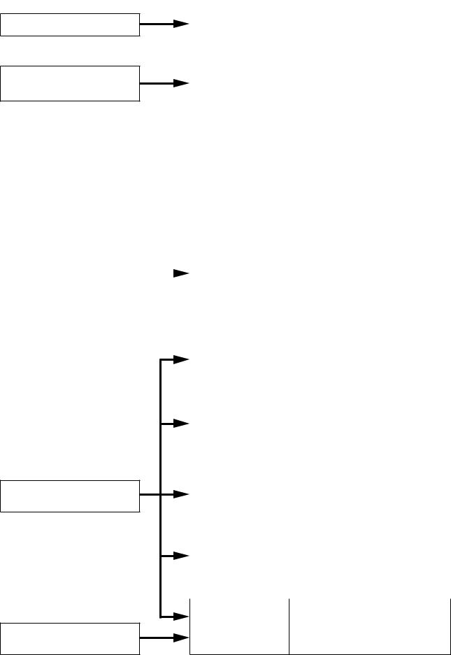
This operating instruction consists of Chapter 1 – 8 as follows. Please read the necessary chapter as required.
To all users
To the person who operates the equipment
Chapter 1 |
• System Configuration |
General Description |
• Nomenclature and Functions |
|
• System Function |
|
|
|
|
Chapter 2 |
• Master Station's Functions and |
Function and |
Operation |
Operation |
• Remote Microphone Station's |
|
Fanctions and Operation |
|
• Door Station's Functions and |
|
Operation |
|
• Substation/Switch Panel's Functions |
|
and Operation |
|
• N-8000AL Telephone Interface |
|
connected Telephone Functions |
|
and Operation |
|
• Operation from Outside Line |
|
Telephone |
|
• Other Functions (useful functions) |
|
• Remarks (list of signal tones) |
|
|
|
Chapter 3 |
• Installation of the Exchange |
|
|
|
Installation and |
• Installation of the Substation |
To the person who installs and |
|
|
Wiring |
Interface Unit |
wires the equipment |
|
|
|
• Installation of the Various Kinds of |
|
|
|
|
Interface Units |
|
|
|
|
|
|
|
|
|
• Installation of Stations |
|
|
|
|
• Wiring |
|
|
|
|
|
To the person who designs and maintains the system
To the person who installs and wires the equipment
Chapter 4 |
• Turning the System's Power |
System Design |
Switch ON |
Precautions |
• Network Settings with a Personal |
|
Computer |
|
• System Setting Items and Default |
|
|
|
|
Chapter 5 |
• General Description |
System Settings by |
• Installation and Activating |
Software |
• Equipment Scan |
|
• System Settings |
|
|
|
|
Chapter 6 |
• Starting the Browser |
System Settings |
• Network Settings |
Using the Browser |
• Operating Status Indication, |
|
Operation Log Indication |
|
• System Administration |
|
|
Chapter 7 |
• Menu Items |
Multifunctional Station |
• Entering Maintenance Screen |
Menu Screen Operation |
• Settings |
(N-8000MS/8500MS only) |
|
|
|
Chapter 8 |
• Basic Knowledge about Networks |
Appendix |
• Trouble Occurs |
|
• Indicator Status & Troubleshooting |
|
• Specifications |
17

Chapter 1
GENERAL DESCRIPTION
This chapter describes the N-8000 Series Packet Intercom System's basic equipment configurations (exchanges, stations and various interface units), component functions and operations, and two types of conversation methods.
Chapter 1 GENERAL DESCRIPTION
1. General Description
The N-8000 Series is a packet intercom system (IP network compatible intercom) employing packet audio technology*1. By connecting IP intercom exchanges (which can connect up to 16 stations per exchange), IP stations, and various kinds of interface units to a network (LAN or WAN*2), an optimal system can be constructed for in-house or wide area information communications such as duplex conversations between stations, periodical broadcasts, and BGM broadcasts. Since up to 192 exchanges, IP stations, and various kinds of interface units can be combined, systems of up to a total of 3072 stations can be realized. An echo canceller*3 and voice switch realize hands-free conversation (conversations made without using a handset at both parties) between stations. Depending on conditions, full duplex (simultaneous two-way) conversation by way of an echo canceller or half duplex (alternate two-way) conversation by way of a voice switch is made. (Refer to p. 8-2, "FULL DUPLEX AND HALF DUPLEX CONVERSATIONS.")
In addition, The system's various interface units and modules can be used to realize a host of functions, including contact bridging by means of contact input and output control, contact external equipment control and timer-activated fixed-time broadcasts, connection to outside lines (central office lines), and broadcast to the SX-2000 system. Further, the system supports two different conversation methods and is capable of operating in master/master or master/sub configurations.
*1 |
Technology related to audio transmission over a network |
*2 |
The fixed global IP address must be assigned to the units connected via the Internet. |
*3 |
A circuit that prevents acoustic feedback or echo generated when the voice output from the station's internal |
|
speaker enters the microphone. |
Warning
This is a class A product. In a domestic environment this product may cause radio interference in which case the user may be required to take adequate measures.
1-2
Chapter 1 GENERAL DESCRIPTION
2. Features
•Exchanges, IP stations, and various kinds of interface units can be connected over a data communications network.
•Can be connected to an existing local area network (LAN) or wide-area network (WAN). The system can also be easily connected to fiber-optic networks without restrictions on operating distance.
•The dedicated software program enables centralized control with a personal computer.
•System maintenance (verifying operation log and Line supervision) can also be performed with a personal computer and Internet browser.
•3 types of exchanges differ in the following points.
(1)2-wire system
N-8000EX: Internal 4 links*, external 8 links*, with PA paging output N-8010EX: Internal 1 link*, external 2 links*, without PA paging output
(2)2-core shielded system N-8000RS: External 2 links* N-8010RS: External 1 link*
(3)4-wire system
N-8400RS: External 2 links*
•4 types of stations are available: 2-wire system, 2-core shielded system, 4-wire system and IP-type stations. The first three stations must be connected to a corresponding system exchange to make operation possible, while the IP station can be operated on its own without being connected to any exchange. (However, the system configured only with IP door stations cannot be realized.)
(1)IP-type
(2)2-wire system
(3)2-core shielded system
(4)4-wire system
•There are five types of interface units as shown below:
(1)Multi interface unit
(2)Audio interface unit
(3)Direct select unit
(4)C/O interface unit
(5)Telephone interface unit
•The Multi interface unit or Direct select unit can interlock with an electronic lock system or CCTV surveillance system by way of contact input/output control function.
•Using IP stations permits a system having no exchange to be created. However, the system configured only with IP door stations cannot be realized.
•Using IP interface modules permits broadcast to the SX-2000 system.
*Link is a speech path. The "internal 4 links" means that 4 simultaneous calls can be performed between the stations connected to an exchange or 4 different broadcasts can be simultaneously made in a system. The "external 8 links" means that 8 simultaneous calls can be made to the stations connected to other exchange or to IP stations, or 8 different broadcasts can be simultaneously made to other exchange system.
3. HANDLING PRECAUTIONS
The Internet is not guaranteed quality. So, when this system is connected to the Internet, packet loss may result if the network is congested, possibly causing voice communications to be interrupted or noise to be generated.
1-3
Chapter 1 GENERAL DESCRIPTION
4. Specifications
Number of Units Connectable to LAN: Maximum 192
(a total of Exchanges, IP stations, and various kinds of interface units)
Line Capacity:
Speech Link Capacity: Single exchange N-8000EX: N-8010EX: N-8400RS:
Unit to unit N-8000EX: N-8010EX: N-8000RS: N-8010RS: N-8400RS: N-8000MI:
SX-200IP:
Paging
Paging zones: Paging outputs:
Maximum 3072 (192 Exchanges x 16 stations per Exchange) Maximum 768 (192 N-8000EX Exchanges)
4 links
1 link
1 link
8 links
2 links
2 links
1link
2links
2links
Speech (through the PBX or tie-line): Maximum 2 links
Audio input: |
Maximum 2 links |
Audio output: |
Maximum 2 links |
Note |
|
The above links can be simultaneously used. (Refer to the table on p. 1-13.)
2 links
Maximum 192
Maximum 384 (When 192 N-8000EX Exchanges or Multi interface units are connected)
N-8000EX: |
2 outputs |
|
N-8000MI: |
2 outputs |
|
N-8000AF: |
1 output |
|
Simultaneous access capacity for paging links: |
|
|
N-8000EX: |
Multicast paging: Maximum 4 links |
|
N-8010EX: |
Unicast paging: |
1 link |
Multicast paging: |
Maximum 2 links |
|
N-8000MI: |
Unicast paging: |
1 link |
Multicast paging: |
Maximum 2 links |
|
N-8000AF: |
Unicast paging: |
1 link |
Multicast paging: |
Maximum 1 link |
|
N-8500MS: |
Unicast paging: |
1 link |
Multicast paging: |
1 link |
|
N-8510MS: |
Unicast paging: |
1 link |
Multicast paging: |
1 link |
|
N-8600MS: |
Unicast paging: |
1 link |
Multicast paging: |
1 link |
|
N-8610RM: |
Unicast paging: |
1 link |
Multicast paging: |
1 link |
|
N-8000AL: |
Unicast paging: |
1 link |
Multicast paging: |
1 link |
|
N-8000CO: |
Unicast paging: |
1 link |
Multicast paging: |
1 link |
|
N-8400RS: |
Unicast paging: |
1 link |
Multicast paging: |
Maximum 2 links |
|
SX-200IP: |
Unicast paging: |
1 link |
Multicast zone broadcast: 2 links |
||
|
Unicast zone broadcast: 2 links |
|
Paging destinations via network: Multicast paging: Maximum 191 |
||
|
Unicast paging: |
Maximum 16 |
(N-8000AL/8000AF/8000CO: Maximum8) Zone broadcast to SX-2000 system: Maximum 16 basses per system
Maximum 128 basses (8 systems)
1-4
|
Chapter 1 GENERAL DESCRIPTION |
BGM: |
Maximum 8 channels (Number of channels selectable at the station) |
PBX Interface: |
Maximum 384 (When 192 Multi interface units are connected) |
Tie-line Interface: |
Maximum 384 (When 192 Multi interface units are connected) |
C/O Interface: |
Maximum 192 (When 192 C/O interface units are connected) |
Telephone Interface: |
Maximum 384 (When 192 Telephone interface units are connected) |
External Contact Output: |
Maximum 3072 (When 192 Multi interface units are connected) |
N-8000MI: |
|
N-8000DI: |
Maximum 6144 (When 192 Direct select units are connected) |
N-8000AF: |
Maximum 1536 (When 192 Audio interface units are connected) |
External Contact Input: |
Maximum 3072 (When 192 Multi interface units are connected) |
N-8000MI: |
|
N-8000DI: |
Maximum 6144 (When 192 Direct select units are connected) |
N-8000AF: |
Maximum 1536 (When 192 Audio interface units are connected) |
System Settings: |
Personal computer setting using a dedicated software program (over LAN) |
(Network Related) |
|
Voice Delay Time: |
80 or 320 ms, selectable |
Connection Delay Time: |
Maximum 1 second (When Multicast paging is made to 191 zones) |
Usage Bandwidth: |
Maximum 2.08 Mbps (one way)/When Unicast paging is made to 16 zones |
|
Maximum 130 kbps (two-way)/one call |
1-5

Chapter 1 GENERAL DESCRIPTION
5. System Configuration
5.1. System Configuration Example
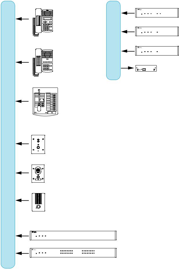
This system consists of the following equipment.
2-wire type exchange N-8000EX/8010EX
2-wire type station
N-8000MS N-8010MS
RS-191 N-8031MS N-8033MS
|
N-8011MS |
N-8020MS |
N-8050DS |
|
|
2-core shielded type exchange N-8000RS/8010RS |
|
||
Network |
2-core shielded type station |
|
||
|
RS-150 RS-160/170 |
RS-180 |
RS-140 RS-142 |
|
|
|
|
|
|
|
|
|
RS-141 |
|
|
|
|
|
RS-143 RS-144 |
|
4-wire type exchange N-8400RS |
|
|
|
|
4-wire type station |
|
|
|
|
|
RS-450 |
RS-460/470 |
RS-480 |
|
N-8410MS |
|
|
RS-481 RS-442 |
|
|
|
|
|
1-6
|
Chapter 1 GENERAL DESCRIPTION |
IP type station |
Audio interface unit N-8000AF |
|
Telephone interface unit N-8000AL |
N-8500MS/8600MS |
Network |
N-8510MS
N-8610RM
Network
N-8540DS
N-8640DS
N-8650DS
Multi interface unit N-8000MI
Direct select unit N-8000DI
C/O interface unit N-8000CO
IP interface module SX-200IP
1-7
5.1.1. Exchange
[2-wire type exchange]
N-8000EX: IP Intercom Exchange N-8010EX: IP Intercom Exchange
[2-core shielded type exchange] N-8000RS: Substation Interface Unit N-8010RS: Substation Interface Unit
[4-wire type exchange]
N-8400RS: Substation Interface Unit
5.1.2. Stations
[IP stations] |
IP Multifunctional Master Station |
N-8500MS: |
|
N-8510MS: |
IP Standard Master Station |
N-8600MS: |
IP Multifunctional Master Station |
N-8610RM: |
IP Remote Microphone Station |
N-8540DS: |
IP Door Station |
N-8640DS: |
IP Door Station |
N-8650DS: |
IP Door Station |
[2-wire type |
stations] |
N-8000MS: |
Multifunctional Master Station |
N-8010MS: |
Standard Master Station |
N-8011MS: |
Standard Hands-Free Master Station |
N-8020MS: |
Industrial-Use Master Station |
N-8031MS: |
Flush-Mount Master Station |
N-8033MS: |
Flush-Mount Master Station |
RS-191: |
Option Handset |
N-8050DS: |
Door Station |
[2-core shielded type stations] |
|
RS-150: |
Substation |
RS-160: |
Substation |
RS-170: |
Substation |
RS-180: |
Substation |
RS-140: |
Switch Panel |
RS-141: |
Option Handset for RS-140/142/143 |
RS-142: |
/144 |
Switch Board |
|
RS-143: |
Switch Panel |
RS-144: |
Switch Panel |
[4-wire type |
stations] |
N-8410MS: |
Analog Standard Master Station |
RS-442: |
Switch Board |
RS-450: |
Substation |
RS-460: |
Substation |
RS-470: |
Substation |
RS-480: |
Substation |
RS-481: |
Option Handset for RS-480 |
Chapter 1 GENERAL DESCRIPTION
5.1.3. Peripheral components
N-8000MI: Multi Interface Unit
N-8000DI: Direct Select Unit N-8000AF: Audio Interface Unit N-8000CO: C/O Interface Unit N-8000AL: Telephone Interface Unit SX-200IP: IP Interface Module
5.1.4. Others
YC-150: Back Box for the N-8050DS/8540DS/ 8640DS/8650DS
YC-241 Back Box for the N-8031MS YC-251: Wall-Mount Box for the N-8031MS YC-280: Wall Mounting Bracket for the
N-8000MS/8010MS/8020MS/8410MS /8500MS/8510MS/8600MS
YC-290: Wall Mounting Bracket for the N-8011MS
YC-302: 2-Gang Electrical Box
YC-801: Flush-Mount Box for the RS-140/143/ 144
YC-802: Wall-Mount Box for the RS-140/143/ 144
YC-822: Wall-Mount Box
YC-823: Wall-Mount Box
YC-841: Wall-Mount Box for the N-8033MS YC-850: Interface Unit Bracket
(For N-8000RS/8010RS/8400RS /8000DI/8000AF/8000CO/8000AL)
YS-13A: Wall-Mount Box for the N-8050DS/8540DS/8640DS/8650DS
AD-1210P: AC Adapter for the N-8500MS/8510MS/ 8600MS/8540DS/8640DS/8650DS
AD-1215P: AC Adapter for the N-8500MS/8510MS/ 8600MS/8540DS/8640DS/8650DS
E-7000TB: 40-Station Terminal Board CR-273: Equipment Rack
CR-413: Equipment Rack
1-8

Chapter 1 GENERAL DESCRIPTION
5.2. Component Description
5.2.1. Exchange
[2-wire type exchange]
•N-8000EX IP Intercom Exchange
The Exchange permits connection of up to sixteen 2-wire type stations and features two outputs for public address paging. The speech links consist of 4 internal links and 8 external links. The exchange is equipped with a networking interface, allowing connection with IP stations, various kinds of interface units, and other IP intercom exchanges. The Exchange can be mounted in an EIA standard rack (1U), to a wall or installed on a desk.
•N-8010EX IP Intercom Exchange
The Exchange permits connection of up to sixteen 2-wire type stations. The speech links consist of 1 internal link and 2 external links.
The exchange is equipped with a networking interface, allowing connection with IP stations, various kinds of interface units, and other IP intercom exchanges.
The Exchange can be mounted in an EIA standard rack (1U), to a wall or installed on a desk.
[2-core shielded type exchange]
•N-8000RS IP Intercom Substation Interface Unit
The Exchange permits connection of up to sixteen 2-core shielded type stations. The speech links consist of 2 external links.
The exchange is equipped with a networking interface, allowing connection with IP stations, various kinds of interface units, and other IP intercom exchanges.
The Exchange can be mounted in an EIA standard rack (1U), to a wall or installed on a desk.
•N-8010RS IP Intercom Substation Interface Unit
The Exchange permits connection of up to sixteen 2-core shielded type stations. The speech link consists of 1 external link.
The exchange is equipped with a networking interface, allowing connection with IP stations, various kinds of interface units, and other IP intercom exchanges.
The Exchange can be mounted in an EIA standard rack (1U), to a wall or installed on a desk.
[4-wire type exchange]
•N-8400RS IP Intercom Substation Interface Unit
The Exchange permits connection of up to sixteen 4-wire type stations. The speech links consist of 1 internal link and 2 external links.
The exchange is equipped with a networking interface, allowing connection with IP stations, multi interface units, and other IP intercom exchanges.
The Exchange can be mounted in an EIA standard rack (1U), to a wall or installed on a desk.
Kind of Exchange |
Model No. |
Communication methods |
Internal Link |
External Link |
|
2-wire type |
N-8000EX |
Audio: Digital PCM |
4 |
8 |
|
exchange |
N-8010EX |
Control: Multiplex system |
1 |
2 |
|
|
|||||
2-core shielded |
N-8000RS |
Audio: Analog base band |
Impossible |
2 |
|
type exchange |
|
|
|
||
N-8010RS |
Control: Current loop system |
1 |
|||
|
|||||
|
|
||||
4-wire type |
N-8400RS |
Audio: Analog base band |
1 |
2 |
|
exchange |
Control: Current loop/pilot tone system |
||||
|
|
|
|||
|
|
|
|
1-9

Chapter 1 GENERAL DESCRIPTION
5.2.2. Stations [IP station]
|
|
|
|
|
|
|
|
|
|
|
|
|
|
|
|
|
|
|
|
|
Specification |
|
|
|
|
|
|
|
|
|
|
|
|
|
|
|
|
|
|||||
Type of Stations |
|
Speech Method |
|
|
|
Installation Method |
|
|
|
LCD |
Auto- |
External |
Control |
Control |
PC |
|
|||||||||||||||||||||||||||
|
|
|
Hands- |
|
|
|
|
|
|
|
Wall |
|
Flush- |
|
Wall |
cascade- |
Power |
||||||||||||||||||||||||||
|
|
Handset |
Headset |
Desk top |
|
|
surface |
Display |
dialing |
speaker |
output |
input |
connection |
|
|||||||||||||||||||||||||||||
|
|
free |
hanging |
|
mounting |
|
mounting |
|
|
|
|
|
|
|
|
|
|
|
|
|
|
|
|
||||||||||||||||||||
N-8500MS: |
|
|
|
|
|
|
|
*1 |
|
*2 |
|
|
|
|
|
|
|
|
|
|
|
|
|
|
|
|
|
|
|
|
|
|
|
|
|
|
|
*3 |
|||||
IP Multifunctional |
|
|
|
|
|
|
|
|
|
|
|
|
|
|
|
|
|
|
|
|
|
|
|
|
|
|
|
|
|
|
|
|
|
|
|
||||||||
Master Station |
|
|
|
|
|
|
|
|
|
|
|
|
|
|
|
|
|
|
|
|
|
|
|
|
|
|
|
|
|
|
|
|
|
|
|
|
|
|
|
|
|
|
|
|
|
|
|
|
|
|
|
|
|
|
|
|
|
|
|
|
|
|
|
|
|
|
|
|
|
|
|
|
|
|
|
|
|
|
|
|
|
|
|
|
|
|
|
N-8510MS: |
|
|
|
|
|
|
|
*1 |
|
*2 |
|
|
|
|
|
|
|
|
|
|
|
|
|
|
|
|
|
|
|
|
|
|
|
|
|
|
|
*3 |
|||||
Standard |
|
|
|
|
|
|
|
|
|
|
|
|
|
|
|
|
|
|
|
|
|
|
|
|
|
|
|
|
|
|
|
|
|
|
|
||||||||
|
|
|
|
|
|
|
|
|
|
|
|
|
|
|
|
|
|
|
|
|
|
|
|
|
|
|
|
|
|
|
|
|
|
|
|
|
|
|
|
|
|
||
Master Station |
|
|
|
|
|
|
|
|
|
|
|
|
|
|
|
|
|
|
|
|
|
|
|
|
|
|
|
|
|
|
|
|
|
|
|
|
|
|
|
|
|
|
|
|
|
|
|
|
|
|
|
|
|
|
|
|
|
|
|
|
|
|
|
|
|
|
|
|
|
|
|
|
|
|
|
|
|
|
|
|
|
|
|
|
|
|
|
N-8600MS: |
|
|
|
|
|
|
|
*1 |
|
*2 |
|
|
|
|
|
|
|
|
|
|
|
|
|
|
|
|
|
|
|
|
|
|
|
|
|
|
|
*3 |
|||||
IP Multifunctional |
|
|
|
|
|
|
|
|
|
|
|
|
|
|
|
|
|
|
|
|
|
|
|
|
|
|
|
|
|
|
|
|
|
|
|
||||||||
|
|
|
|
|
|
|
|
|
|
|
|
|
|
|
|
|
|
|
|
|
|
|
|
|
|
|
|
|
|
|
|
|
|
|
|
|
|
|
|
|
|
||
Master Station |
|
|
|
|
|
|
|
|
|
|
|
|
|
|
|
|
|
|
|
|
|
|
|
|
|
|
|
|
|
|
|
|
|
|
|
|
|
|
|
|
|
|
|
|
|
|
|
|
|
|
|
|
|
|
|
|
|
|
|
|
|
|
|
|
|
|
|
|
|
|
|
|
|
|
|
|
|
|
|
|
|
|
|
|
|
|
|
N-8610RM: |
|
|
|
|
|
|
|
|
|
|
|
*4 |
|
|
|
|
|
|
|
|
|
|
|
|
|
|
|
|
|
|
|
|
|
|
|
|
|
|
|
*3 |
|||
IP Remote |
|
|
|
|
|
|
|
|
|
|
|
|
|
|
|
|
|
|
|
|
|
|
|
|
|
|
|
|
|
|
|
|
|
|
|
|
|
|
|||||
|
|
|
|
|
|
|
|
|
|
|
|
|
|
|
|
|
|
|
|
|
|
|
|
|
|
|
|
|
|
|
|
|
|
|
|
|
|
|
|
|
|
||
Microphone Station |
|
|
|
|
|
|
|
|
|
|
|
|
|
|
|
|
|
|
|
|
|
|
|
|
|
|
|
|
|
|
|
|
|
|
|
|
|
|
|
|
|
|
|
|
|
|
|
|
|
|
|
|
|
|
|
|
|
|
|
|
|
|
|
|
|
|
|
|
|
|
|
|
|
|
|
|
|
|
|
|
|
|
|
|
|
|
|
N-8540DS: |
|
|
|
|
|
|
|
|
|
|
|
|
|
|
|
*5 |
|
*6 |
|
|
|
|
|
|
|
|
|
|
|
|
|
|
|
|
|
|
|
*3 |
|||||
IP Door Station |
|
|
|
|
|
|
|
|
|
|
|
|
|
|
|
|
|
|
|
|
|
|
|
|
|
|
|
|
|
|
|
|
|
|
|
|
|
|
|
|
|
|
|
|
|
|
|
|
|
|
|
|
|
|
|
|
|
|
|
|
|
|
|
|
|
|
|
|
|
|
|
|
|
|
|
|
|
|
|
|
|
|
|
|
|
|
|
N-8640DS: |
|
|
|
|
|
|
|
|
|
|
|
|
|
|
|
*5 |
|
*6 |
|
|
|
|
|
|
|
|
|
|
|
|
|
|
|
|
|
|
|
*3 |
|||||
IP Door Station |
|
|
|
|
|
|
|
|
|
|
|
|
|
|
|
|
|
|
|
|
|
|
|
|
|
|
|
|
|
|
|
|
|
|
|
|
|
|
|
|
|
|
|
|
|
|
|
|
|
|
|
|
|
|
|
|
|
|
|
|
|
|
|
|
|
|
|
|
|
|
|
|
|
|
|
|
|
|
|
|
|
|
|
|
|
|
|
N-8650DS: |
|
|
|
|
|
|
|
|
|
|
|
|
|
|
|
*5 |
|
*6 |
|
|
|
|
|
|
|
|
|
|
|
|
|
|
|
|
|
|
|
*3 |
|||||
IP Door Station |
|
|
|
|
|
|
|
|
|
|
|
|
|
|
|
|
|
|
|
|
|
|
|
|
|
|
|
|
|
|
|
|
|
|
|
|
|
|
|
|
|
|
|
|
|
|
|
|
|
|
|
|
|
|
|
|
|
|
|
|
|
|
|
|
|
|
|
|
|
|
|
|
|
|
|
|
|
|
|
|
|
|
|
|
|||
*1 |
The front operation panel can be inclined 16° from the desk surface by attaching the YC-280 Wall Mounting |
||||||||||||||||||||||||||||||||||||||||||
*2 |
Bracket to its bottom surface. |
|
|
|
|
|
|
|
|
|
|
|
|
|
|
|
|
|
|
|
|
|
|
|
|
|
|
|
|
|
|
|
|
||||||||||
A dedicated YC-280 Wall Mounting Bracket is required. |
|
|
|
|
|
|
|
|
|
|
|
|
|
|
|
|
|
|
|
|
|
|
|
||||||||||||||||||||
*3 |
A PoE (Power over Ethernet) switching hub compliant with IEEE802.3af or optional AD-1210P/1215P AC |
||||||||||||||||||||||||||||||||||||||||||
*4 |
Adapter is required. |
|
|
|
|
|
|
|
|
|
|
|
|
|
|
|
|
|
|
|
|
|
|
|
|
|
|
|
|
|
|
|
|
|
|
|
|
|
|
|
|||
A dedicated WB-RM200 Wall Mount Bracket is required. |
|
|
|
|
|
|
|
|
|
|
|
|
|
|
|
|
|
|
|
|
|
|
|
||||||||||||||||||||
*5 |
A dedicated YC-150 Back box is required. |
|
|
|
|
|
|
|
|
|
|
|
|
|
|
|
|
|
|
|
|
|
|
|
|
|
|
|
|||||||||||||||
*6 |
A dedicated YS-13A Wall-mount box is required. |
|
|
|
|
|
|
|
|
|
|
|
|
|
|
|
|
|
|
|
|
|
|
|
|
|
|
|
|||||||||||||||
1-10
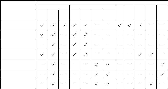
Chapter 1 GENERAL DESCRIPTION
[2-wire type station] |
|
|
|
|
|
|
|
|
|
|
|
|
|
|
|
|
|
|
Specification |
|
|
|
|
|
|
Type of Stations |
Speech Method |
Installation Method |
Wall |
LCD |
Auto- |
External |
Control |
External |
||||
|
|
|
|
|
|
|||||||
|
Handset |
Hands- |
Headset |
Desk top |
Wall |
Flush- |
Display |
dialing |
speaker |
output |
dial input |
|
|
surface |
|||||||||||
|
|
free |
|
|
hanging |
mounting |
mounting |
|
|
|
|
|
N-8000MS: Multifunctional |
|
|
|
*1 |
*3 |
|
|
|
|
|
|
|
Master Station |
|
|
|
|
|
|
|
|
|
|
|
|
N-8010MS: Standard |
|
|
|
*1 |
*3 |
|
|
|
|
|
|
|
Master Station |
|
|
|
|
|
|
|
|
|
|
|
|
N-8011MS: Standard |
|
|
|
*2 |
*4 |
|
|
|
|
|
|
|
Hands-Free Master Station |
|
|
|
|
|
|
|
|
|
|
|
|
N-8020MS: Industrial-Use |
|
|
|
*1 |
*3 |
|
|
|
|
|
|
|
Master Station |
|
|
|
|
|
|
|
|
|
|
|
|
N-8031MS: Flush-Mount |
*5 |
|
|
|
|
*6 |
*8 |
|
|
|
|
|
Master Station |
|
|
|
|
|
|
|
|
|
|
|
|
N-8033MS: Flush-Mount |
|
|
|
|
|
*10 |
*10 |
|
|
|
|
|
Master Station |
|
|
|
|
|
|
|
|
|
|
|
|
N-8050DS: Door Station |
|
|
|
|
|
*7 |
*9 |
|
|
|
|
|
*1 |
The front operation panel can be inclined 16° from the desk surface by attaching the YC-280 Wall Mounting |
*2 |
Bracket to its bottom surface. |
The front operation panel can be inclined 16° from the desk surface by attaching the YC-290 Wall Mounting |
|
*3 |
Bracket to its bottom surface. |
A dedicated YC-280 Wall Mounting Bracket is required. |
|
*4 |
A dedicated YC-290 Wall Mounting Bracket is required. |
*5 |
Permits handset conversation when used in conversation with the RS-191 Option Handset |
*6 |
A dedicated YC-241 Back Box is required. |
*7 |
A dedicated YC-150 Back box is required. |
*8 |
A dedicated YC-251 Wall-mount box is required. |
*9 |
A dedicated YS-13A Wall-mount box is required. |
*10 |
A dedicated YC-841 Wall-Mount Box is required. |
1-11
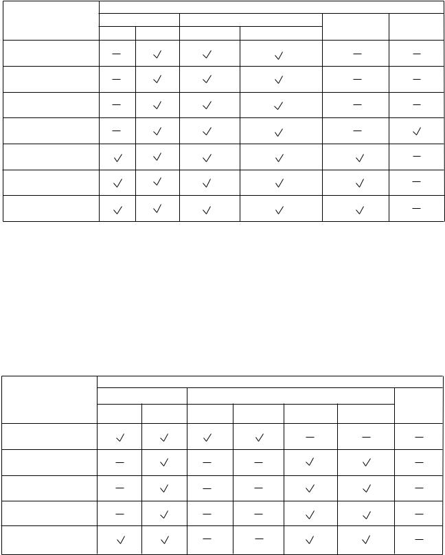
Chapter 1 GENERAL DESCRIPTION
[2-core shielded station] |
|
|
|
|
|
|
|
|
|
|
Specification |
|
|
Type of Stations |
Speech Method |
Installation Method |
External speaker |
Control output |
||
|
Handset |
Hands-free |
Flush-mounting |
Wall surface mounting |
||
|
|
|
||||
RS-150: |
|
|
*1 |
*2 |
|
|
Sub Station |
|
|
|
|
|
|
RS-160: |
|
|
*1 |
*2 |
|
|
Sub Station |
|
|
|
|
|
|
RS-170: |
|
|
*1 |
*2, *3 |
|
|
Sub Station |
|
|
|
|
|
|
RS-180: |
|
|
*1 |
*2, *3 |
|
|
Sub Station |
|
|
|
|
|
|
RS-140: |
*4 |
*5 |
*6 |
*7 |
*5 |
|
Switch Panel |
|
|
|
|
|
|
RS-143: |
*4 |
*5 |
*6 |
*7 |
*5 |
|
Switch Panel |
|
|
|
|
|
|
RS-144: |
*4 |
*5 |
*6 |
*7 |
*5 |
|
Switch Panel |
|
|
|
|
|
|
*1 |
A dedicated YC-302 2-Gang Electrical Box is required. |
*2 |
A dedicated YC-822 Wall-Mount Box is required. |
*3 |
A dedicated YC-823 Wall-Mount Box is required. |
*4 |
Permits handset conversation when used in conversation with the RS-141 Option Handset |
*5 |
Connection to an already installed 25 V line speaker allows it to be used for conversation applications (as |
*6 |
it can be made to function both as a microphone and a speaker). |
A dedicated YC-801 Flush-Mount Box is required. |
|
*7 |
A dedicated YC-802 Wall-Mount Box is required. |
[4-wire type station] |
|
|
|
|
|
|
|
|
|
|
|
Specification |
|
|
|
Type of Stations |
Speech Method |
|
Installation Method |
|
Control |
||
|
|
|
|
|
|
||
|
Handset |
Hands-free |
Desk |
Wall |
Flush- |
Wall surface |
output |
|
top |
hanging |
mounting |
mounting |
|
||
|
|
|
|
||||
N-8410MS: Analog |
|
|
*1 |
*2 |
|
|
|
Standard Master Station |
|
|
|
|
|
|
|
RS-450: |
|
|
|
|
*3 |
*4 |
|
Sub Station |
|
|
|
|
|
|
|
RS-460: |
|
|
|
|
*3 |
*4 |
|
Sub Station |
|
|
|
|
|
|
|
RS-470: |
|
|
|
|
*3 |
*4, *5 |
|
Sub Station |
|
|
|
|
|
|
|
RS-480: |
*6 |
|
|
|
*3 |
*4, *5 |
|
Sub Station |
|
|
|
|
|
|
|
*1 |
The front operation panel can be inclined 16° from the desk surface by attaching the YC-280 Wall Mounting |
|
*2 |
Bracket to its bottom surface. |
|
A dedicated YC-280 Wall Mounting Bracket is required. |
||
*3 |
A dedicated YC-302 |
2-Gang Electrical Box is required. |
*4 |
A dedicated YC-822 |
Wall-Mount Box is required. |
*5 |
A dedicated YC-823 |
Wall-Mount Box is required. |
*6 |
Permits handset conversation when used in conversation with the RS-481 Option Handset |
|
1-12
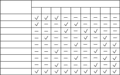
Chapter 1 GENERAL DESCRIPTION
5.2.3. Peripheral components
[N-8000MI Multi Interface Unit]
Having 2 channels each for audio input and output, and 16 contacts each for control input and output, the N-8000MI performs the following interface functions*.
•Tie-line interface for connection with the EXES-2000 and EXES-6000 systems.
•PBX interface for connection with the PBX via the analog E&M interface.
•PA paging interface for connection with PA equipment
•External input broadcast interface for connection with a music player (chime unit) or paging microphone irrespective of with or without remote control function.
•Interface function that enables external broadcast by connecting a paging microphone or a playing device without a Remote Control function.
•Interface to control an indicator or external equipment such as a CCTV's switcher using relay contacts.
•Interface function that enables Calling Station Display and Remote Dialing functions for designated
Master Stations using contact input and output.
•Interface function that uses contact output to diagnose system line and network statuses and transmits the diagnosed result.
The N-8000MI also features Network interface for connection with IP stations, IP intercom exchanges, and various kinds of interface units.
The N-8000MI interface is a rack-mounted model (1U size), but can be used for desktop and wall-mount applications as well.
* The interface functions can be combined in the following 9 patterns.
Interface function |
|
|
|
Combination pattern |
|
|
|
|||
1 |
2 |
3 |
4 |
5 |
6 |
7 |
8 |
9 |
||
|
||||||||||
PBX 1 |
|
|
|
|
|
|
|
|
|
|
PBX 2 |
|
|
|
|
|
|
|
|
|
|
Tie-line 1 |
|
|
|
|
|
|
|
|
|
|
Tie-line 2 |
|
|
|
|
|
|
|
|
|
|
Audio output 1 |
|
|
|
|
|
|
|
|
|
|
Audio output 2 |
|
|
|
|
|
|
|
|
|
|
Audio input 1 |
|
|
|
|
|
|
|
|
|
|
Audio input 2 |
|
|
|
|
|
|
|
|
|
|
Contact IN/OUT |
|
|
|
|
|
|
|
|
|
|
[N-8000AF Audio Interface Unit]
Having 1 channel for audio input and output, and 8 contacts each for control input and output, and 1 contact for time sync input , the N-8000AF performs the following interface functions.
•PA paging interface for connection with PA equipment
•External input broadcast interface for connection with a music player (chime unit) or paging microphone irrespective of with or without remote control function.
•Interface function that enables external broadcast by connecting a paging microphone or a playing device without a Remote Control function.
•The Time Signal function enables the N-8000AF to activate its built-in timer at preset times to play its built-in sound source or an external playing device by closing the contact output terminal.
•The Interface function records the designated Master Station's conversation on an external recorder by outputting the conversation from the N-8000AF's audio output and transmitting it to the recorder activated when the N-8000AF's contact output terminal is closed.
•NTP Client function synchronizes the clock of the N-8000AF with NTP server when the NTP Client function of the N-8000AF set to the clock master is enabled.
The N-8000AF also features Network interface for connection with IP stations, IP intercom exchanges, and various kinds of interface units.
The N-8000AF is a rack-mounted model (1U size and half-size width), but can be used for desktop and wallmount applications as well.
1-13
 Loading...