


Operation Instruction Manual
TOA 500 SERIES
MIXER POWER AMPLIFIER


A-503A A-506A A-512A
Features |
General Description |
1.High quality design and construction.
2.Full frequency response: 50 - 15,000Hz, ±3dB.
3.Low distortion and noise level.
4.4 microphone inputs, 3 auxiliary inputs and a mag. phono input.
5.Isolated-transformer outputs complete with 4 ohms, 25V and 70V.
6.AC/DC operation: 120V AC and 24V DC
7.Individual bass and treble tone controls.
8.Signal processing input/output.
9.Self-protection circuitry design.
10.Muting function.
11.Remote volume control circuit.
TheTOA 500 series Mixer Power Amplifiers A-512A, A-506A and A-503A are designed for PA system applications such as paging, announcements, intercommunications, background music and broadcasting in industrial plants, offices, schools, churches, department stores, shopping centers, night clubs, dining rooms, convention halls, auditoriums and recreation areas.
The Primary feature is their ability to withstand overload or short-circuits of output. Because of the TOA-engineered circuitry design, the TOA 500 -series amplifiers require no complicated protective circuit to withstand accidents and mismatched output connections that may occur during the installation or use of a PA system. This results in very high reliability.
The 500 series amplifiers come with 4 microphone inputs, 3 auxiliary inputs and a mag. phono input. Input 1 (Mic 1) and Input 2 (Mic 2) out of the 4 mic inputs are balanced inputs, while Input 3 (Mic 3) and Input 4 (Mic 4) are of unbalanced type. Input 3 and Input 4 can be changed to balanced type with the LI-51 microphone input module (optional). Two condenser microphone can be used with phantom power supplied from Input 1 and 2. And they have a remote volume control circuit on Input 2 as the volume can be adjusted at the microphone even when it is distant from the amplifier. The amplifiers are equipped with muting function.
They may be used in conjunction With a speaker rated at 4 ohms or with 25volt, 70volt constant-voltage speaker systems. Three auxiliary inputs and a mag. phono input are provided with RCA pin jack. Preamp-Out and Power-Amp-ln receptacles are provided for easy connection of a signal processor to the amplifier.
Emergency operation can be made by DC power source (24V DC) even in case of AC power failure.
TOA Corporation |
133-02-767-7A |
KOBE, JAPAN |
Printed in Taiwan |

TOA 500 SERIES
Front Panel Controls and Features
No. |
Name |
Function/Description |
|
1 |
Power on-off switch |
Applies line power. Two position button switch for on-off modes. |
|
2 |
Power |
indicator |
Comes on when power is turned on. |
3 |
Input 1 - 5 volume controls |
Adjusts gain of Input 1-5 respectively. |
|
4 |
Bass |
control |
Adjusts bass response. |
|
|
|
Turn clockwise (CW) to boost and counterclockwise (CCW) to attenuate |
|
|
|
the bass response. Tone is flat at center. |
5 |
Treble |
control |
Adjusts treble response. |
|
|
|
Turn clockwise (CW) to boost and counterclockwise (CCW) to attenuate |
|
|
|
the treble response. Tone is flat at center. |
6 |
Master volume control |
Adjusts overall gain of unit. |
|
Block Diagram
A-503A, A-506A, A-512A
BLOCK DIAGRAM

No. |
|
Name |
Function/Description |
1 |
AC power supply cord |
Connects to AC power supply. |
|
2 |
AC outlet (unswitched) |
Provides AC power for auxiliary equipment with power consumption |
|
|
|
|
of up to 500W. |
3 |
AC fuse |
Prevents excessive current flow. |
|
4 |
24V DC terminals |
Connect to DC power supply (24V). |
|
5 |
Output terminals |
Connect to speakers. |
|
6 |
Input 1 (Mic 1), |
Connect to microphones of balanced 200 ohms with XLR |
|
|
Input 2 (Mic 2) inputs |
connectors. |
|
7 |
Pahntom power ON/OFF switch |
This switch is to be turned on when using the condenser |
|
|
(Mic |
1, Mic 2) |
microphone. |
8 |
Input 3 (Mic 3), |
Input 4 (Mic 4) inputs |
These screw terminal inputs connect to unbalanced 50k ohms |
|
|
|
microphone. |
9 |
Input 3 (Mic 3/Mag. phono) select switch |
Selects Mic 3 or Mag. phono input. |
|
10 |
Input 4 (Mic 4/Aux 1) select switch |
Selects Mic 4 or Aux 1 input. |
|
11 |
Mag. phono input |
Connects to the record player with MM type cartridge. |
|
12 |
Aux 1 - 3 inputs |
Connect aux inputs. |
|
13 |
Aux 3 volume control |
Adjusts gain of Aux 3. |
|
14 |
Tape output |
Provides connections for a tape recorder. The input impedance of |
|
|
|
|
the equipment should be more than 4.7k ohms. |
15 |
Booster output |
Provides connections for a booster amplifier. The input impedance |
|
|
|
|
of the equipment should be more than 600 ohms. |
16 |
Preamp output |
Connects to a signal processing equipment such as a limiter, |
|
|
|
|
equalizer etc. The input impedance of the equipment should be |
|
|
|
more than 600 ohms. |
|
|
|
In this case, Link switch should be set the "OUT" position. |
17 |
Power amp input |
When using this terminal, set Link switch to "OUT". |
|
18 |
Link switch |
Disconnects between preamplifier and power amplifier when this |
|
|
|
|
switch is set to "OUT", allowing the connection of other equipment. |
19 |
Remote volume control terminals |
Mic 2 volume can be adjusted by means of a 10k-ohms |
|
|
|
|
potentiometer connected to these terminals. |
20 |
Mute terminals |
Short-circuiting these terminals mutes input signals (inputs 3-5). |
|
|
(adjustable muted level: 0 - 30dB) |
|
|
21 |
Earth terminal |
Normally connects to record player's ground. |
|
- 2 -
TOA 500 SERIES
Installation
Do not block cover ventilation holes.
The amplifier should not be placed in areas;
1)with poor ventilation.
2)exposed to direct sunlight.
3)With high ambient temperature or adjacent to heat-generating equipment.
4)with high humidity or dust levels.
5)susceptible to vibration.
CAUTION
Do not remove the cover to prevents an electric shock.
Input Connections
A. Microphone
Four microphone inputs are provided. Two of them may be used with balanced low impedance (30 - 600 ohms) microphone, or with condenser microphone. The other may be used with an unbalanced high impedance (50k ohms) microphone. The microphone with the unbalanced connection cable of 30 - 70ft or balanced cable 70 - 230ft may be used depending on the microphone and its characteristic.
Mic 1 and Mic 2
1)for dynamic microphones — Low impedance (30 - 600 ohms) balanced microphone inputs are provided with a XLR connector.
2)for condenser microphones - Condenser microphones can be used with supplying DC 15V phantom power, while turning on the phantom power switch above the mic input connector.
Mic 3 and Mic 4 — High impedance (50k ohms) unbalanced type microphone inputs are provided with screw terminals.
Using Mic 3 input, the Input 3 select switch must be turned to Mic 3. Using Mic 4 input, the Input 4 select switch must be turned to Mic 4.
B. Record player
Record player with MM (moving magnet type) cartridge may be connected to Mag. Phono input (2mV, 50k ohms).
Use single or double conductor shielded cable with a terminating RCA pin plug. It is recommended that a separate ground wire be connected between the record player base and the earth (  ) screw terminal on the rear panel.
C. Radio tuner, cassette tape player and other BGM sources A radio tuner, tape player, chime, mixer preamplifier, compact disk player or other high level signal sources may be connected to the AUX-1, AUX-2 or AUX-3 input.
Use single or double conductor shielded cable with a terminating
RCA pin plug.
Output Connections
Speaker output
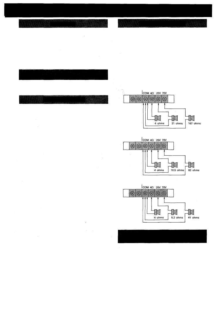
The speaker outputs of the amplifier are 4 ohms, 25V, and 70V. Connect the speakers cable to one of these outputs, after removing the screw terminal cover. Put the cover back on when finished the connection.
Class 2 wiring may be used.
Since these outputs consist of 4 ohms, 25V and 70V via the output transformer (matching transformer) the connecting method differs in each case.
See the following diagrams.
Note: Impedances indicated below imply total speaker system
(load) impedances.
<A-503A>
Output Terminal
<A-506A>
Output Terminal
<A-512A>
Output Terminal
CAUTION
When connecting speakers to any one of the outputs of 4 ohms, 25V or 70V.
- 3 -
 Loading...