


INSTALLATION AND
OPERATING INSTRUCTIONS
(Applicable to the 9000M2 firmware Ver. 2.00 or later)
9000M2 SERIES AMPLIFIERS M-9000M2 A-9060DHM2 A-9120DHM2 A-9060SM2 A-9120SM2 A-9240SHM2
Please also read the separate instruction manual for the programming software in conjunction with this manual.
Thank you for purchasing TOA's 9000M2 series Amplifier.
Please carefully follow the instructions in this manual to ensure long, trouble-free use of your equipment.
TABLE OF CONTENTS |
|
|
1. |
IMPORTANT SAFETY INSTRUCTIONS ................................................................ |
6 |
2. |
SAFETY PRECAUTIONS ............................................................................................ |
7 |
3. |
GENERAL DESCRIPTION .......................................................................................... |
9 |
4. |
FEATURES .................................................................................................................... |
10 |
5. |
INSTALLATION PRECAUTIONS ............................................................................ |
11 |
6. |
HANDLING PRECAUTIONS .................................................................................... |
11 |
7. |
NOMENCLATURE AND FUNCTIONS |
|
|
7.1. 9000M2 Series Amplifier |
|
|
[Front] .......................................................................................................................... |
12 |
|
[VFD on-screen indications] ........................................................................................ |
13 |
|
[Changing the indicated channels on the LEVEL output meter] .................................. |
15 |
|
[Changing the input and output meter display status] ................................................. |
15 |
|
[Rear] .......................................................................................................................... |
16 |
|
7.2. Optional Modules |
|
|
7.2.1. D-001T and D-001R (2-channel Input Modules) ............................................... |
18 |
|
7.2.2. T-001T (Audio Output Expansion Module) ........................................................ |
18 |
|
7.2.3. ZP-001T (Zone Paging Module) ........................................................................ |
19 |
|
7.2.4. C-001T (Control I/O Expansion Module) ........................................................... |
20 |
|
7.2.5. AN-001T (Ambient Noise Sensor Input Module) ............................................... |
20 |
|
7.2.6. RC-001T (Remote Control Module) .................................................................. |
21 |
|
7.3. Optional Accessories |
|
|
7.3.1. AN-9001 (Ceiling Mount Microphone) ............................................................... |
22 |
|
7.3.2. ZM-9001 (Zone Manager) ................................................................................. |
23 |
|
7.3.3. ZM-9002 (Zone Manager) ................................................................................. |
24 |
|
7.3.4. ZM-9003 (Zone Manager) ................................................................................. |
25 |
|
7.3.5. ZM-9011 (Remote Control Panel) ..................................................................... |
26 |
|
7.3.6. ZM-9012 (Remote Control Panel) ..................................................................... |
27 |
|
7.3.7. ZM-9013 (Remote Control Panel) ..................................................................... |
28 |
|
7.3.8. ZM-9014 (Remote Control Panel) ..................................................................... |
29 |
|
7.3.9. SS-9001 (Speaker Selector) ............................................................................. |
31 |
8. |
OPERATION OUTLINE |
|
|
8.1. Using as a Mixer Amplifier ........................................................................................... |
32 |
|
8.2. Using as a Paging Amplifier |
|
|
8.2.1. Paging using the D-001T, D-001R, or 900 series module ................................ |
33 |
|
8.2.2. Paging using the ZP-001T module .................................................................... |
34 |
|
8.2.3. Cross point ON/OFF control using the remote controller .................................. |
36 |
|
8.3. Glossary ...................................................................................................................... |
40 |
2
9. OPERATION |
|
9.1. Basic Operation |
|
9.1.1. Keys and knobs ................................................................................................. |
43 |
9.1.2. Power ON/OFF ................................................................................................. |
43 |
9.1.3. Changing the input parameters ......................................................................... |
43 |
9.1.4. Changing the output parameters ....................................................................... |
44 |
9.1.5. Input channel ON/OFF ...................................................................................... |
44 |
9.1.6. Output channel ON/OFF ................................................................................... |
44 |
9.2. Recalling Scene Memory ............................................................................................ |
45 |
9.3. Making Zone Paging |
|
9.3.1. Zone paging using the D-001T, D-001R, or 900 series module ........................ |
46 |
9.3.2. Zone paging using the ZP-001T module ........................................................... |
48 |
9.4. Releasing Key Lock ..................................................................................................... |
50 |
9.5. Operation Example ...................................................................................................... |
51 |
10.SETTINGS
10.1. Setting Menu Configuration and Flow for Entering Each Screen
10.1.1. Input setting configuration ............................................................................. |
52 |
10.1.2. Output setting configuration .......................................................................... |
52 |
10.1.3. Utility setting configuration ............................................................................ |
53 |
10.1.4. Scene memory setting configuration ............................................................. |
53 |
10.1.5. Confirming set items ..................................................................................... |
53 |
10.2. Input Setting Flow Chart |
|
10.2.1. Input setting flow chart for the channel |
|
on which the D-001T or D-001R is used ......................................................... |
54 |
10.2.2. Input setting flow chart for the channel on which the ZP-001T is used ......... |
56 |
10.2.3. Input setting flow chart for the channel on which the AN-001T is used ....... |
57 |
10.2.4. Input setting items ......................................................................................... |
58 |
10.3. Output Setting Flow Chart ......................................................................................... |
69 |
10.3.1. Output setting items ...................................................................................... |
70 |
10.4. UTILITY Setting Flow Chart ...................................................................................... |
75 |
10.4.1. Control input terminal's function settings ....................................................... |
77 |
10.4.2. Control output terminal's function settings .................................................... |
77 |
10.4.3. Utility setting items ........................................................................................ |
78 |
10.5. Key Lock Function Setting |
|
10.5.1. Keys that can be locked ................................................................................ |
90 |
10.5.2. Password setting ........................................................................................... |
91 |
10.5.3. Key lock setting operation ............................................................................. |
92 |
10.6. SCENE MEMORY Setting Flow Chart ....................................................................... |
93 |
10.6.1. Scene memory setting items ......................................................................... |
94 |
11. HOW TO STORE OR ERASE SCENE MEMORY |
|
11.1. Recalling Scene Memory .......................................................................................... |
96 |
11.2. Storing Scene Memory .............................................................................................. |
97 |
11.3. Erasing Scene Memory ............................................................................................. |
98 |
11.4. Setting the Scene Memory to be Recalled at Power-On ........................................... |
99 |
3
12. RESTORING FACTORY DEFAULT SETTING ................................................. |
100 |
12.1. Default Setting Table |
|
12.1.1. Items regarding system settings ................................................................. |
101 |
12.1.2. Items regarding Scene settings ................................................................... |
103 |
12.1.3. Items regarding paging settings .................................................................. |
105 |
13. MODULE INSTALLATION |
|
13.1. Module Combination ............................................................................................... |
106 |
13.2. Channel Numbers and Terminal Numbers .............................................................. |
106 |
13.3. Module Installation .................................................................................................. |
106 |
13.4. Module Installation Examples .................................................................................. |
108 |
14. CONNECTIONS |
|
14.1. Control I/O Terminal Connections |
|
14.1.1. When a variable resistor or variable DC power supply unit is connected .... |
109 |
14.1.2. When the ZM-9001 or ZM-9002 is connected ............................................. |
110 |
14.1.3. When the ZM-9003 is connected ................................................................ |
110 |
14.1.4. When the SS-9001 is connected ................................................................. |
110 |
14.1.5. Operation by control input ........................................................................... |
111 |
14.2. Speaker Output Terminal Connections |
|
14.2.1.A-9060SM2 and A-9120SM2 ....................................................................... |
112 |
14.2.2.A-9060DHM2 and A-9120DHM2 .................................................................. |
113 |
14.2.3.A-9240SHM2 ................................................................................................ |
113 |
14.3. C-001T Module Connections |
|
14.3.1. Control input terminal .................................................................................. |
114 |
14.3.2. Control output terminal ................................................................................ |
114 |
14.3.3. Connecting the ZM-9003 ............................................................................. |
114 |
14.3.4. Connecting the SS-9001 ............................................................................. |
115 |
14.4. RC-001T Module Connection |
|
14.4.1. Connection method ..................................................................................... |
116 |
14.4.2. Cable distance ............................................................................................ |
117 |
14.5. RS-232C Connector Connection ............................................................................. |
120 |
14.6. AN-001T and AN-9001 Connections ....................................................................... |
121 |
14.7. Power Source Connections to the SS-9001 |
|
14.7.1. When using a 24 V DC power source ......................................................... |
121 |
14.7.2. When using the optional AC adapter .......................................................... |
121 |
14.8. Removable Terminal Plug Connection .................................................................... |
122 |
15. RACK MOUNTING BRACKET ATTACHMENT ............................................... |
123 |
16. AN-9001 INSTALLATION ........................................................................................ |
124 |
17. DIMENSIONAL DIAGRAMS |
|
17.1. AN-9001 .................................................................................................................. |
125 |
17.2. ZM-9001 .................................................................................................................. |
126 |
17.3. ZM-9002 .................................................................................................................. |
126 |
4
17.4. ZM-9003 .................................................................................................................. |
127 |
17.5. ZM-9011 .................................................................................................................. |
128 |
17.6. ZM-9012 .................................................................................................................. |
128 |
17.7. ZM-9013 .................................................................................................................. |
129 |
17.8. ZM-9014 .................................................................................................................. |
130 |
17.9. SS-9001 .................................................................................................................. |
131 |
18. OUTLINE OF THE ATTACHED SOFTWARE ................................................... |
132 |
19. ERROR INDICATIONS ............................................................................................. |
133 |
20. TROUBLESHOOTING ............................................................................................. |
134 |
21. BLOCK DIAGRAM .................................................................................................... |
135 |
22. SIGNAL FLOW DIAGRAM ..................................................................................... |
136 |
23. LEVEL DIAGRAM ...................................................................................................... |
137 |
24. COMPRESSION CHARACTERISTICS DIAGRAM ......................................... |
138 |
25. SPEAKER PRESET PARAMETER LIST ........................................................... |
139 |
26. SPECIFICATIONS |
|
26.1. M-9000M2 ............................................................................................................... |
145 |
26.2. A-9060DHM2, A-9120DHM2 ................................................................................... |
147 |
26.3. A-9060SM2, A-9120SM2 ........................................................................................ |
149 |
26.4. A-9240SHM2 ........................................................................................................... |
151 |
26.5. Optional Modules |
|
26.5.1. D-001T ........................................................................................................ |
153 |
26.5.2. D-001R ........................................................................................................ |
154 |
26.5.3. T-001T ......................................................................................................... |
155 |
26.5.4. C-001T ........................................................................................................ |
156 |
26.5.5. ZP-001T ...................................................................................................... |
156 |
26.5.6. AN-001T ...................................................................................................... |
157 |
26.5.7. RC-001T ...................................................................................................... |
157 |
26.6. Optional Accessories |
|
26.6.1. AN-9001 ...................................................................................................... |
158 |
26.6.2. ZM-9001 ...................................................................................................... |
158 |
26.6.3. ZM-9002 ...................................................................................................... |
159 |
26.6.4. ZM-9003 ...................................................................................................... |
159 |
26.6.5. ZM-9011 ...................................................................................................... |
160 |
26.6.6. ZM-9012 ...................................................................................................... |
160 |
26.6.7. ZM-9013 ...................................................................................................... |
161 |
26.6.8. ZM-9014 ...................................................................................................... |
161 |
26.6.9. SS-9001 ...................................................................................................... |
162 |
5

1. IMPORTANT SAFETY INSTRUCTIONS
•Read these instructions.
•Keep these instructions.
•Heed all warnings.
•Follow all instructions.
•Do not use this apparatus near water.
•Clean only with dry cloth.
•Do not block any ventilation openings. Install in accordance with the manufacturer's instructions.
•Do not install near any heat sources such as radiators, heat registers, stoves, or other apparatus (including amplifiers) that produce heat.
•Do not defeat the safety purpose of the polarized or grounding-type plug. A polarized plug has two blades with one wider than the other. A grounding type plug has two blades and a third grounding prong. The wide blade or the third prong are provided for your safety. If the provided plug does not fit into your outlet, consult an electrician for replacement of the obsolete outlet.
•Protect the power cord from being walked on or pinched particularly at plugs, convenience receptacles, and the point where they exit from the apparatus.
•Only use attachments/accessories specified by the manufacturer.
•Use only with the cart, stand, tripod, bracket, or table specified by the manufacturer, or sold with the apparatus. When a cart is used, use caution when moving the
cart/apparatus combination to avoid injury from tip-over.
•Unplug this apparatus during lightning storms or when unused for long periods of time.
•Refer all servicing to qualified service personnel. Servicing is required when the apparatus has been damaged in any way, such as power-supply cord or plug is damaged, liquid has been spilled or objects have fallen into the apparatus, the apparatus has been exposed to rain or moisture, does not operate normally, or has been dropped.
FCC REQUIREMENTS
Note: This equipment has been tested and found to comply with the limits for a Class A digital device, pursuant to Part 15 of the FCC Rules. These limits are designed to provide reasonable protection against harmful interference when the equipment is operated in a commercial environment. This equipment generates, uses, and can radiate radio frequency energy and, if not installed and used in accordance with the instruction manual, may cause harmful interference to radio communications. Operation of this equipment in a residential area is likely to cause harmful interference in which case the user will be required to correct the interference at his own expense.
6
2. SAFETY PRECAUTIONS
•Before installation or use, be sure to carefully read all the instructions in this section for correct and safe operation.
•Be sure to follow all the precautionary instructions in this section, which contain important warnings and/or cautions regarding safety.
•After reading, keep this manual handy for future reference.
Safety Symbol and Message Conventions
Safety symbols and messages described below are used in this manual to prevent bodily injury and property damage which could result from mishandling. Before operating your product, read this manual first and understand the safety symbols and messages so you are thoroughly aware of the potential safety hazards.
The exclamation point within an equilateral triangle is intended to alert the user to the presence of important operation and maintenance (servicing) instruction in the literature accompanying the appliance.
WARNING |
Indicates a potentially hazardous situation which, if mishandled, |
could result in death or serious personal injury. |
When Installing the Unit
•Do not expose the unit to rain or an environment where it may be splashed by water or other liquids, as doing so may result in fire or electric shock.
•Use the unit only with the voltage specified on the unit. Using a voltage higher than that which is specified may result in fire or electric shock.
•Do not cut, kink, otherwise damage nor modify the power supply cord. In addition, avoid using the power cord in close proximity to heaters, and never place heavy objects -- including the unit itself -- on the power cord, as doing so may result in fire or electric shock.
•Avoid installing or mounting the unit in unstable locations, such as on a rickety table or a slanted surface. Doing so may result in the unit falling down and causing personal injury and/or property damage.
•External wiring connected to the terminals marked with  requires installation by an instructed person.
•The apparatus shall be connected to a mains socket outlet with a protective earthing connection.
•The socket-outlet shall be installed near the equipment and the plug shall be easily accessible.
•Use the supplied rack mounting bracket when mounting the unit in an equipment rack. Remove four M4 x 8 screws on both sides of the unit, and mount the bracket there using the supplied M4 x 16 screws instead.
When the Unit is in Use
•Should the following irregularity be found during use, immediately switch off the power, disconnect the power supply plug from the AC outlet and contact your nearest TOA dealer. Make no further attempt to operate the unit in this condition as this may cause fire or electric shock.
·If you detect smoke or a strange smell coming from the unit
·If water or any metallic object gets into the unit
·If the unit falls, or the unit case breaks
·If the power supply cord is damaged (exposure of the core, disconnection, etc.)
·If it is malfunctioning (no tone sounds.)
•To prevent a fire or electric shock, never open nor remove the unit case as there are high voltage components inside the unit. Refer all servicing to your nearest TOA dealer.
•Do not place cups, bowls, or other containers of liquid or metallic objects on top of the unit. If they accidentally spill into the unit, this may cause a fire or electric shock.
7
CAUTION |
Indicates a potentially hazardous situation which, if mishandled, could |
result in moderate or minor personal injury, and/or property damage. |
When Installing the Unit
•Never plug in nor remove the power supply plug with wet hands, as doing so may cause electric shock.
•When unplugging the power supply cord, be sure to grasp the power supply plug; never pull on the cord itself. Operating the unit with a damaged power supply cord may cause a fire or electric shock.
•Do not block the ventilation slots in the unit's cover. Doing so may cause heat to build up inside the unit and result in fire.
•Avoid installing the unit in humid or dusty locations, in locations exposed to the direct sunlight, near the heaters, or in locations generating sooty smoke or steam as doing otherwise may result in fire or electric shock.
•To avoid electric shocks, be sure to unplug the unit's power supply cord when connecting speakers.
•Be sure to follow the instructions below when rack-mounting the unit. Failure to do so may cause a fire or personal injury.
·Install the equipment rack on a stable, hard floor. Fix it with anchor bolts or take other arrangements to prevent it from falling down.
·When connecting the unit's power cord to an AC outlet, use the AC outlet with current capacity allowable to the unit.
·No rack-mounting screws are supplied with the unit. Separately prepare the appropriate screws for the rack.
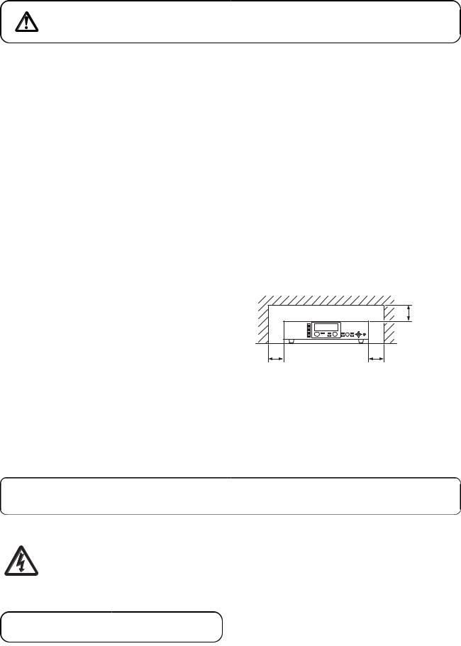
•Keep the 9000M2 series amplifiers over 10 cm (3.94") away from objects that may obstruct air flow to prevent the unit's internal temperature rise.
Over 10 cm |
(3.94”) |
Over 10 cm (3.94”) |
Over 10 cm (3.94”) |
When the Unit is in Use
•Do not operate the unit for an extended period of time with the sound distorting. This is an indication of a malfunction, which in turn can cause heat to generate and result in a fire.
•Switch off the power, and unplug the power supply plug from the AC outlet for safety purposes when cleaning or leaving the unit unused for 10 days or more. Doing otherwise may cause a fire or electric shock.
An all-pole mains switch with a contact separation of at least 3 mm in each pole shall be incorporated in the electrical installation of the building.
The lighting flash with arrowhead symbol, within an equilateral triangle, is intended to alert the user to the presence of uninsulated "dangerous voltage" within the product's enclosure that may be of sufficient magnitude to constitute a risk of electric shock to persons.
 ATTENTION
L'appareil ne doit pas être exposé aux éclaboussures ou écoulements et tous objets remplis de liquide, tels que vases, ne doivent pas être sur l'appareil.
8
3. GENERAL DESCRIPTION
TOA's 9000M2 Series Amplifiers are designed to be used in conjunction with optional modules and can be configured for up to 8 inputs and 8 outputs. Usable modules include the following 9000 series plug-in modules: D-001T and D-001R (2-channel input), T-001T (Audio output expansion), C-001T (Control I/O expansion), ZP-001T (Zone paging), AN-001T (Ambient noise sensor), and RC-001T (Remote controller interface), as well as 900 series input modules. The most appropriate modules can be selected depending on applications.
The 9000M2 Series Amplifier can be used as a mixer that is appropriate for speech or sound reinforcement applications. It is equipped with signal processing and control functions, permitting all parameters to be set at the amplifier.
Each input can also be set as a paging input, to which one of 3 priority levels can be assigned.
The paging input takes precedence over other mixing inputs, thus allowing priority paging calls to go through to the designated outputs. Paging calls can be activated by triggers of various types. Multiple paging calls can be selectively used according to their priority levels. Thus, the 9000M2 Series Amplifier can effectively meet a room combining application.
Setting data of both mixing and paging functions can be stored inside the amplifier.
The M-9000M2 is a Pre-Amplifier featuring the above functions.
Besides the M-9000M2's function, the following 9000M2 Series Amplifiers come with power amplifiers, out of which A-9060DHM2 and A-9120DHM2 can perform 2-channel or stereo broadcast in stand-alone operation.
A-9060DHM2: |
60 |
W (70 V output) x 2 |
A-9120DHM2: |
120 |
W (70 V output) x 2 |
A-9060SM2: |
60 W x 1 |
|
A-9120SM2: |
120 W x 1 |
|
A-9240SHM2: |
240 |
W (70 V output) x 1 |
All settings that can be made at the unit can also be made on the PC using the supplied dedicated software.
[Compatibility of the firmware version and software version]
This instruction manual supports the 9000M2 Series amplifiers' firmware Ver. 2.00 or later and the PC Setting software Ver. 2.00 or later.
Some of the functions described in this manual do not work on the firmware and PC software versions earlier than Ver. 2.00. If you use the older version of the 9000M2, update the firmware and PC software versions to the latest ones. Also, be sure to back up the 9000M2's setting data using the PC Setting software before performing updates.
Notes
•While performing version update, make sure to prevent the power cable and communication cable from accidentally coming off.
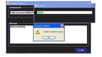
•Once updated to firmware Ver. 2.00 or later, you cannot downgrade back to firmware Ver. 2.00 or earlier. The indication "INVALID VERSION" is displayed on the 9000M2 amplifier's front-mounted display (VFD) and PC's screen when attempting to perform downgrade. (Refer to the screen shot below.)
The indication is displayed for a few seconds, then the 9000M2 amplifier restarts with the version remaining unchanged.
9
4. FEATURES
•Can be configured as a mixer or paging amplifier by settings, depending on application.
•Eight module slots enable audio input and output configuration ranging from 1 input and 1 output to 8 inputs and 8 outputs.
•All settings can be performed at the unit using the built-in vacuum fluorescent display (VFD), setting keys and Parameter setting knob on the front panel.
•Paging calls can be made from the designated outputs by setting the paging source, priority, and trigger even while the unit is being used as a mixer.
•Up to 32 mixing settings can be stored as Scene memory, which can be recalled by the unit or external connected equipment.
•Different paging calls can be selectively used depending on situations as two or more paging sources can be set and different priority levels can be assigned to them. Other functions allow paging calls to be activated with various types of triggers and up to 32 paging groups to be saved independently of scene memory.
•An RS-232C port permits remote control of the unit using an AMX*1 or Crestron*2 controller, or similar external equipment.
•With the use of the optional AN-001T Ambient Noise Sensor Input module and AN-9001 Ceiling Mount Microphone, the amplifier's output volume can be automatically adjusted in response to the change in ambient noise level.
•Using the optional RC-001T Remote Control Module in conjunction with the Remote control panels such as ZM-9011, ZM-9012, ZM-9013, or ZM-9014 permits operations including scene and sound source switchings, paging initiation, control output ON/OFF, and volume adjustment to be remotely controlled.
•The optional ZM-9001 Zone Manager adds 6 control inputs, while the optional ZM-9002 Zone Manager adds 4 control inputs and 1 volume control.
•A ducker function*3 permits paging calls to be made without interrupting BGM broadcasts. Besides, an automixing function (ducker function*3 and NOM attenuation function*4) automatically adjusts the output gain.
*1 AMX is a trademark of AMX Corporation.
*2 Crestron is a trademark of Crestron Electronics, Inc.
*3 The Ducker function automatically attenuates input signals with lower priority when two or more audio signals are simultaneously received.
*4 The NOM (Number of Open Microphones) attenuation function automatically adjusts the output channel gain depending on the number of open microphones.
10
5. INSTALLATION PRECAUTIONS
•Keep the 9000M2 Series Amplifiers over 10 cm (3.94") away from objects that may obstruct air flow to prevent the unit's internal temperature rise.
|
|
|
|
|
|
|
|
Over 10 cm (3.94”) |
INPUT SELECT |
|
|
|
|
|
|
|
|
1 |
|
|
|
|
|
|
|
|
2 |
|
|
|
|
|
|
|
|
3 |
|
|
|
|
|
|
|
|
4 |
|
|
|
|
|
|
|
|
5 |
INPUT VOLUME |
ON/OFF |
ON/OFF |
OUTPUT VOLUME |
MEMORY |
PARAMETER |
UTILITY |
POWER |
6 |
|
|
|
|
|
|
|
|
7 |
|
|
OUTPUT SEL |
|
ENTER |
|
ESC/BACK |
|
8 |
|
|
|
|
|
|
|
|
Over 10 cm (3.94”) |
|
|
Over 10 cm (3.94”) |
|
|
|
|
|
|
|
|
|
|
|
•When mounting the unit on an equipment rack
·Use the supplied rack-mounting bracket. (For the bracket attachment, refer to p. 123 "RACK MOUNTING BRACKET ATTACHMENT.")
·Have the unit well-ventilated, and be sure to mount a 1U or more size perforated panel above and below the unit to prevent the unit's internal temperature rise.
9000M2 Series amplifier
INPUT SELECT |
|
|
|
|
1 |
|
|
|
|
2 |
|
|
|
|
3 |
|
|
|
|
4 |
|
|
|
|
5 |
INPUT VOLUME |
OUTPUT VOLUME |
PARAMETER |
POWER |
6 |
|
|
|
|
7 |
|
|
|
|
8 |
|
|
|
|
Perforated panels
6. HANDLING PRECAUTIONS
•The supplied power supply cord is designed for exclusive use with this unit. Never use it with other equipment.
•Use the unit in locations where the temperature is between –10 and +40°C or 14 and 104°F (no condensation should be formed), and the humidity is less than 80%.
•The unit is a precision audio component. To prevent failure, avoid locations where it may be exposed to strong shocks or vibrations.
•To clean, be sure to first disconnect the power supply plug from the AC outlet, then wipe with a dry cloth. When extremely dirty, use a soft cloth dampened in neutral detergent. Never use benzene, thinner, alcohol or chemically-treated towels, which may damage the unit's finish.
11
7. NOMENCLATURE AND FUNCTIONS
7.1. 9000M2 Series Amplifiers
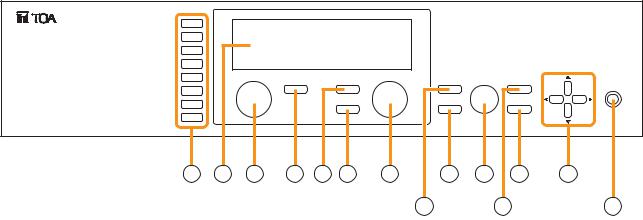
[Front]
INPUT SELECT |
|
|
|
|
1 |
|
|
|
|
2 |
|
|
|
|
3 |
|
|
|
|
4 |
|
|
|
|
5 |
INPUT VOLUME |
OUTPUT VOLUME |
PARAMETER |
POWER |
|
ON/OFF |
ON/OFF |
MEMORY |
UTILITY |
6 |
|
|
|
|
7 |
|
OUTPUT SEL |
ENTER |
ESC/BACK |
|
|
|
|
|
8 |
|
|
|
|
2 |
3 |
4 |
5 |
6 |
7 |
8 |
10 |
11 |
13 |
14 |
|
|
|
|
|
|
9 |
|
|
12 |
1 |
1.Power switch and Power indicator
Press this switch to turn on the power. The power indicator lights. To turn off the power, hold down the switch for at least 0.5 second.
Note
The power switch is a soft-switch, so the internal microcomputer is still operating even when the power switch is set to OFF.
2.Input channel selection keys
Select the input channel for which the volume is adjusted or parameter is set.
Pressing the key causes the corresponding red channel indicator to light on the vacuum fluorescent display (VFD).
3.Vacuum fluorescent display (VFD)
Displays the setting screen, input and output selection status, channel ON/OFF status, input and output level meter indication, and fader position.
The VFD enters the display saver mode if no key is operated for a fixed period of time.
(Refer to p. 13 "VFD on-screen indications.")
4.Input volume control
Adjusts the gain of the input channel selected with the input channel selection key (2).
5.Input channel ON/OFF key
Turns on or off the channel selected with the input channel selection key (2).
6.Output channel ON/OFF key
Turns on or off the channel selected with the output channel selection key (7).
7.Output channel selection key
Selects the output channel for which the volume is adjusted or parameter is set. The output channel indicators on the VFD light in sequence each time the key is pressed.
8.Output volume control
Adjusts the gain of the output channel selected with the output channel selection key (7).
9.Memory key
Used to save the current settings into a Scene memory or recall a saved Scene setting.
10.Enter key
Press this key when "OK ?" is displayed in the setting screen or when proceeding to the next screen.
11.Parameter setting knob
Rotate this knob to select the setting item or setting contents.
12.Utility menu key
Used to perform Utility setting.
13.Escape/Back key
Used to revert back to a previous screen when advanced with the Enter key during setting operation, or return to the screen on the upper hierarchy level.
14.Screen shift keys [ 


 ]
]
Move the setting screen or setting item.
12
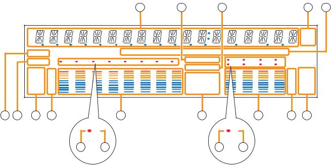
[VFD on-screen indications] |
|
|
|
|
|
|
|
|
|
|
|
|
|
|||||
|
|
|
|
|
|
|
|
15 |
|
16 |
|
17 |
|
|
|
|
18 |
19 |
|
|
|
|
|
|
|
|
|
|
|
|
|
|
|
|
|
d B |
|
|
|
|
|
|
|
|
|
|
|
|
|
|
|
|
|
|
k Hz |
|
|
|
|
|
|
|
|
|
|
|
|
|
|
|
|
|
|
m sec |
|
|
|
COM |
|
|
|
|
GAIN |
|
d B |
|
Q |
|
|
|
|
FREQ |
|
|
|
|
|
|
|
|
|
|
|
|
|
|
|
|
|
|
|
|
|
|
|
FAULT |
1 |
2 |
3 |
4 |
5 |
6 |
7 |
8 |
KEYLOCK |
1 |
2 |
3 |
4 |
|
|
|
|
|
EMERGENCY |
5 |
6 |
7 |
8 |
|
|
||||||||||
|
|
|
|
|
|
|
|
|
|
|
|
|
||||||
|
|
FADER |
OL |
|
|
|
|
|
|
|
|
|
|
OL |
FADER |
|
||
|
|
|
|
|
|
|
|
|
|
|
|
|
|
|
||||
|
|
|
0 |
|
|
|
|
|
|
|
TONE |
GATE |
|
|
|
0 |
|
|
|
|
|
–10 |
|
|
|
|
|
|
|
LOUD |
DUCK |
|
|
|
–10 |
|
|
|
|
|
–20 |
|
|
|
|
|
|
|
|
|
|
–20 |
|
|
||
|
|
|
|
|
|
|
|
|
|
EQ |
NOM |
|
|
|
|
|
||
|
|
LEVEL |
–30 |
|
|
|
|
|
|
|
|
|
|
–30 |
LEVEL |
|
||
|
|
|
|
|
|
|
|
|
COMP |
DELAY |
|
|
|
|
||||
|
|
|
–40 |
|
|
|
|
|
|
|
|
|
|
–40 |
|
|
||
20 |
21 |
22 |
23 |
|
|
|
26 |
|
|
|
27 |
|
|
|
30 |
31 |
32 |
|
|
|
|
|
|
3 |
|
|
|
|
|
|
|
5 |
|
|
|
|
|
|
|
|
|
24 |
|
25 |
|
|
|
|
|
28 |
|
29 |
|
|
|
|
15.14-Segment,18-digit alphanumeric display
Displays the corresponding setting screen or data when each function key is pressed. Parameters being edited flash.
16.Keylock indicator
Lights when the key lock function is enabled, and flashes while the key lock function is being edited.
17.Emergency indicator
Lights when the control input set for "Emergency mute" becomes active.
18.Unit indicator
Displays the unit of each parameter when it is set.
19.GAIN, dB, Q, FREQ indicators
Lights when the equalizer is adjusted.
20.COM indicator
Remains lit during communications via the RS232C interface.
21.Fault indicator
Lights or flashes when the unit's failure or other abnormal conditions are detected.
(Refer to p. 133 "ERROR INDICATIONS.")
22.Input meter status indicator
Indicates which the input level (LEVEL) or input fader position (FADER) is being displayed on the input meter (26).
Note
Input level is displayed only when the D-001T/R module is used.
23.Input level indication
Scale of levels (in dB) for the input meter.
24.Input channel selection indicator (red dot)
Lights when the corresponding input channel is selected, and flashes while parameters are being edited.
25.Input channel ON/OFF indicator (channel number)
The indicators for all channels normally light regardless of whether or not the channels can be selected by the input channel selection keys (2) or can be used (p. 135 "Remarks"), while they flash when turned off by the input channel ON/OFF key (5).
The indicators of unused channels can be set to be off in the Utility setting item.
26.Input meter
Indicates the signal level or input fader position of each input channel.
Which the meter is indicating is displayed on the input meter status indicator (22).
Notes
•The input meter is kept on even for the channel that is turned off or muted.
•Input level is displayed only when the D-001T/R module is used.
27.Effect indicator
Lights when effect is on, and flashes while the parameters are being edited.
13
28.Output channel selection indicator (red dot)
Lights when the corresponding output channel is selected, and flashes while parameters are being edited.
29.Output channel ON/OFF indicator (channel number)
Lights when the corresponding output is on (i.e. in operation mode), and flashes when off.
The number of channels of which indicators light depends on the modules used.
30.Output meter
Indicates the signal level or output fader position of each output channel. Which the meter is indicating is displayed on the output meter status indicator (32).
Notes
•When the output channel 1 or 2 of the A- 9060DHM2/9120DHM2, or the output channel 1 of the A-9060SM2/ 9120SM2/9240SHM2 is turned off or muted, the corresponding output channel's meter becomes off.
•Even when the output channel 2 of the A- 9060SM2/9120SM2/9240SHM2, the M- 9000M2's output channel 1 or 2, or the T- 001T's output channel is turned off or muted, the output meter for these channels remains on.
•The output meters corresponding to the output channel 2 of the A-9060SM2/9120SM2/ 9240SHM2 and T-001T's output channel are not influenced by their output volume control settings.
31.Output level indication
Scale of levels (in dB) for the output meter.
32.Output meter status indicator
Indicates which the output level (LEVEL) or output fader position (FADER) is being displayed on the output meter (30).
Notes
•The VFD automatically enters the display saver mode and indicates “DISPLAY SAVER MODE. PRESS ANY KEY” scrolling sideways if no key is operated for 20 minutes. In this case, the VFD reverts to normal if any key is pressed. Be sure to press any key to make the VFD active before performing any operation.
•The VFD is a consumable item. Its brightness decreases by half after about 30000 hours of continuous lighting.
A built-in display saver mode that automatically dims the VFD light will extend the life of VFD.
14
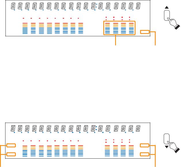
[Changing the indicated channels on the LEVEL output meter]
The output meter indicates the signal levels of only a set of 4 channels: CH 1 – 4 (factory-preset) or CH 5 – 8. When the input or output gain setting screen is displayed, pressing the Up shift key alternately switches the level indication between CH 1 – 4 and CH 5 – 8.
The LEVEL indicator of the output meter status indicator flashes while the CH 5 – 8 are indicated, and stays lit while the CH 1 – 4 are indicated.
In the same manner, the output meter also changes in the Fader indication.
|
|
|
|
|
|
|
|
|
|
|
|
|
|
|
|
d B |
|
|
|
|
|
|
|
|
|
|
|
|
|
|
|
k |
Hz |
|
|
|
|
|
|
|
|
|
|
|
|
|
|
|
m sec |
|
COM |
|
|
|
|
GAIN |
|
d B |
|
Q |
|
|
|
|
FREQ |
|
|
|
|
|
|
|
|
|
|
|
|
|
|
|
|
|
|
|
FAULT |
1 |
2 |
3 |
4 |
5 |
6 |
7 |
8 |
KEYLOCK |
1 |
2 |
3 |
4 |
|
|
|
EMERGENCY |
5 |
6 |
7 |
8 |
|
|
||||||||||
|
|
|
|
|
|
|
|
|
|
|
||||||
FADER |
OL |
|
|
|
|
|
|
|
|
|
|
OL |
FADER |
|||
|
|
|
|
|
|
|
|
|
|
|
|
|||||
|
0 |
|
|
|
|
|
|
|
TONE |
GATE |
|
|
|
0 |
|
|
|
–10 |
|
|
|
|
|
|
|
LOUD |
DUCK |
|
|
|
–10 |
|
|
|
–20 |
|
|
|
|
|
|
|
|
|
|
–20 |
|
|
||
|
|
|
|
|
|
|
|
EQ |
NOM |
|
|
|
|
|
||
LEVEL |
–30 |
|
|
|
|
|
|
|
|
|
|
–30 |
LEVEL |
|||
|
|
|
|
|
|
|
COMP |
DELAY |
|
|
|
|||||
|
–40 |
|
|
|
|
|
|
|
|
|
|
–40 |
|
|
||
Output meters |
Output meter status indicator |
[Changing the input and output meter display status]
When the input or output gain setting screen is displayed, pressing the Down shift key alternately switches the input and output meter display status between the signal level and the fader position.
The LEVEL indicators on both input and output meters light when the signal levels are indicated, while the FADER indicators light when the fader positions are indicated.
When an input channel's gain setting screen is displayed, the meter display status can be switched between the signal level and fader position each time the input channel selection key of the channel being set is pressed.
|
|
|
|
|
|
|
|
|
|
|
|
|
|
|
d B |
|
|
|
|
|
|
|
|
|
|
|
|
|
|
|
k Hz |
|
|
|
|
|
|
|
|
|
|
|
|
|
|
|
m sec |
COM |
|
|
|
|
GAIN |
|
d B |
|
Q |
|
|
|
|
FREQ |
|
|
|
|
|
|
|
|
|
|
|
|
|
|
|
|
|
FAULT |
1 |
2 |
3 |
4 |
5 |
6 |
7 |
8 |
KEYLOCK |
1 |
2 |
3 |
4 |
|
|
EMERGENCY |
5 |
6 |
7 |
8 |
|
||||||||||
|
|
|
|
|
|
|
|
|
|
||||||
FADER |
OL |
|
|
|
|
|
|
|
|
|
|
OL |
FADER |
||
|
|
|
|
|
|
|
|
|
|
|
|
||||
|
0 |
|
|
|
|
|
|
|
TONE |
GATE |
|
|
|
0 |
|
|
–10 |
|
|
|
|
|
|
|
LOUD |
DUCK |
|
|
|
–10 |
|
|
–20 |
|
|
|
|
|
|
|
|
|
|
–20 |
|
||
|
|
|
|
|
|
|
|
EQ |
NOM |
|
|
|
|
||
LEVEL |
–30 |
|
|
|
|
|
|
|
|
|
|
–30 |
LEVEL |
||
|
|
|
|
|
|
|
COMP |
DELAY |
|
|
|
||||
|
–40 |
|
|
|
|
|
|
|
|
|
|
–40 |
|
||
Input meter status indicators Output meter status indicators
Note: The figure above is the VFD screen display when the input and output levels are indicated.
15

[Rear] |
|
|
|
|
|
|
• M-9000M2 |
|
|
|
|
|
|
|
CTRL |
|
|
|
|
|
|
I/O |
|
|
|
|
|
|
REMT |
IN |
|
|
|
|
|
VOL1 |
E |
|
|
PRE |
H |
|
|
IN |
|
|
|
|
|
|
E |
|
|
AMP |
C |
|
REMT |
1 |
|
|
OUT 1 |
E |
|
VOL2 |
2 |
|
|
|
H : Hot |
|
IN |
3 |
|
|
|
|
|
4 |
|
|
|
C : Cold |
|
|
|
|
|
|
||
|
|
E |
|
|
|
E : Earth |
|
|
1 |
|
|
PRE |
H |
|
|
2 |
|
|
||
|
OUT |
|
|
|
||
|
3 |
|
|
AMP |
C |
|
|
RS-232C |
|
|
|||
|
|
4 |
|
|
OUT 2 |
E |
|
|
E |
|
|
|
|
|
35 |
37 |
38 |
39 |
|
40 |
34 |
36 |
|
|
|
|
|
• A-9060DHM2, A-9120DHM2 |
|
|
|
|
||
WARNING |
CTRL |
|
PRE |
|
DO NOT CONNECT |
I/O |
|
AMP |
|
NEGATIVE(–) TERMINALS |
|
|||
REMT |
|
OUT 1 |
||
TOGETHER. |
IN |
|||
|
||||
|
VOL1 |
E |
|
|
|
|
|
IN |
|
|
PWR |
|
SP |
|
|
|
|
|
AMP |
|
|
|
|
|
E |
|
|
|
||
OUT |
|
|
REMT |
1 |
|
|
IN 1 |
|
+ |
|
|
VOL2 |
2 |
|
|
|
|
70V |
CLASS 2 WIRING |
IN |
3 |
|
|
PRE |
|
|
– |
OUT 1 |
4 |
|
|
|
|||
|
|
|
|
AMP |
|
|||
+ |
70V |
|
|
E |
|
|
OUT 2 |
|
|
|
1 |
|
|
|
|
||
– |
OUT 2 |
|
OUT |
2 |
|
|
PWR |
|
|
RS-232C |
|
3 |
|
|
|
||
|
|
|
|
AMP |
|
|||
|
|
|
|
4 |
|
|
|
|
|
|
|
|
|
|
IN 2 |
|
|
|
|
|
|
E |
|
|
|
|
|
|
|
|
|
|
|
|
|
33 |
|
354 |
|
37 |
38 |
39 |
|
40 |
34 |
36 |
|
|
|
|
|
|
|
• A-9060SM2, A-9120SM2 |
|
|
|
|
||||
SPK |
|
|
CTRL |
|
|
|
PRE |
|
|
|
I/O |
|
|
|
|
||
OUT |
|
|
REMT |
IN |
|
|
AMP |
|
|
|
|
|
|
OUT 1 |
|
||
|
|
|
VOL1 |
E |
|
|
|
|
70 V |
|
|
|
|
|
|
||
|
|
|
IN |
|
|
|
|
|
25 V |
|
|
|
|
|
PWR |
|
|
|
|
|
E |
|
|
|
||
|
|
|
REMT |
1 |
|
|
AMP |
|
COM |
|
VOL2 |
2 |
|
|
IN |
H : Hot |
|
CLASS 2 WIRING |
IN |
3 |
|
|
|
|||
TRANS IN |
4 |
|
|
|
C : Cold |
|||
|
|
|
|
|
||||
|
|
|
|
|
E : Earth |
|||
|
|
|
|
E |
|
|
|
|
|
|
|
|
|
|
|
|
|
E |
|
|
|
1 |
|
|
PRE |
H |
|
|
|
2 |
|
|
|||
RS-232C |
OUT |
|
|
AMP |
C |
|||
|
3 |
|
|
|||||
|
|
|
|
OUT 2 |
|
|||
|
|
|
|
4 |
|
|
E |
|
|
|
|
|
|
|
|
||
|
|
|
|
E |
|
|
|
|
33 |
|
354 |
|
37 |
38 |
39 |
40 |
|
34 |
36 |
|
|
|
|
|
|
|
• A-9240SHM2 |
|
|
|
|
|
|
||
WARNING
DO NOT CONNECT |
CTRL |
|
PRE |
|
NEGATIVE(–) TERMINALS |
I/O |
|
||
REMT |
|
AMP |
||
CHASSIS. |
IN |
|||
OUT 1 |
||||
|
VOL1 |
E |
||
|
|
|||
|
|
|
SP |
|
|
IN |
|
|
PWR |
|
|
|
E |
|
|
|||
OUT |
|
REMT |
1 |
|
|
AMP |
|
+ |
|
VOL2 |
2 |
|
|
IN |
H : Hot |
CLASS 2 WIRING |
IN |
3 |
|
|
|
||
+ |
4 |
|
|
|
C : Cold |
||
70V |
|
|
|
|
|||
– |
|
E |
|
|
|
E : Earth |
|
|
|
1 |
|
|
|
H |
|
– |
|
|
2 |
|
|
PRE |
|
|
OUT |
|
|
|
|||
RS-232C |
|
|
AMP |
C |
|||
|
|
3 |
|
|
|||
|
|
|
|
OUT 2 |
|
||
|
|
|
4 |
|
|
E |
|
|
|
|
|
|
|
||
|
|
|
E |
|
|
|
|
33 |
354 |
|
37 |
38 |
39 |
|
40 |
34 |
36 |
|
|
|
|
|
|
16
33.Speaker output terminal
Connect speakers of which total impedance matches the amplifier's output impedance. (Refer to p.112 "Speaker Output Terminal Connections.")
34.AC inlet
Connect the supplied power cord.
35.RS-232C serial communication port
Connector for communications with a personal computer or control equipment.
36.Functional earth terminal
Hum noise may be generated when external equipment is connected to the unit. Connecting this terminal to the functional earth terminal of the external equipment may reduce the hum noise.
Note: This terminal is not for protective earth.
37.Control-I/O connection terminal
Connect a 10 kΩ (linear taper) variable resistor or input the DC voltage of 0 to +10 V to the remote volume control terminals (REMT VOL 1 and 2) when remotely adjusting the volume.
To perform other remote control operation, connect the ZM-9001 or ZM-9002 Zone Manager.
Input and output terminals (IN and OUT) are used to change the unit's internal status or output internal status data to external equipment after having received various control signals.
38.Blank panel (accessory)
Attach the blank panels to open slots.
39.Module slots
900 Series or 9000 Series modules can be inserted into these slots.
(Refer to p. 106 "MODULE INSTALLATION.")
40.Preamplifier output
and Power amplifier input terminals
[M-9000M2]
There are 2 preamplifier output terminals.
For unbalanced connection, connect the unit's Hot and Earth terminals to the connected equipment's Signal and GND terminals, respectively. (Keep the unit's Cold terminal free.)
0 dB, 600 Ω, balanced type
[A-9060DHM2/9120DHM2]
There are 2 preamplifier output terminals and 2 power amplifier input terminals.
Connecting a plug to the power amplifier input terminal internally disconnects the preamplifier section from the power amplifier section.
Both terminals: 0 dB, 300 Ω, unbalanced type
[A-9060SM2/9120SM2/9240SHM2]
There are 2 preamplifier output terminals and 1 power amplifier input terminal.
Connecting a plug to the power amplifier input terminal internally disconnects the preamplifier section 1 from the power amplifier section.
To make unbalanced connection to the preamplifier output 2, connect the output's Hot and Earth terminals to the external equipment's Signal and GND (or Earth) terminals, respectively.
(Keep the unit's Cold terminal free.) Preamplifier output 1: 0 dB, 300 Ω, unbalanced Preamplifier output 2: 0 dB, 600 Ω, balanced
17
7.2. Optional Modules
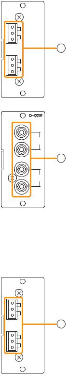
7.2.1. D-001T and D-001R (2-Channel Input Modules)
The D-001T and D-001R modules are designed for use with the 9000M2 Series amplifiers. Up to 4 modules (8 channels in total) can be inserted into the amplifier.
Both modules can handle signals ranging from microphone level (–60 dB) to line level (–10 dB) in 9 input sensitivity levels. They have an internal digital signal processor that can process input signals.
The D-001T can supply phantom power (24 V).
The D-001T or D-001R is required to use a VOX (Voice Operated Exchange) function and input channel level meter.
[D-001T] D-001T
1
Hot
Cold
Earth
1
2
Hot
Cold
Earth
[D-001R]
 1
1
1
2
[D-001T]
1. Monaural input terminals [1, 2]
Electronically-balanced input terminals.
Type of connector: 3P removable terminal blocks Input level: –60 dB to –10 dB selectable
Input impedance: 10 kΩ when the phantom power is OFF, and 3 kΩ when ON
[D-001R]
1. Monaural input terminals [1, 2]
Unbalanced input terminals. Type of connector: RCA jacks
Input level: |
–60 dB to –10 dB selectable |
Input impedance: |
10 kΩ |
Two inputs of each channel are mixed.
7.2.2. T-001T (Audio Output Expansion Module)
The T-001T module is designed for use with the 9000M2 Series amplifiers and can expand 2 output channels per module.
Since the main unit has 2 fixed outputs, the audio output can be expanded to 8 channels by using a maximum of 3 modules (6 channels).
T-001T |
2. Monaural output terminals [1, 2] |
|
|
|
|
1 |
Electronically-balanced 3P removable terminal blocks. |
|
Output level: |
0 dB |
|
Hot |
Output impedance: 600 Ω |
|
Cold |
||
Earth |
For unbalanced connection, connect the unit's Hot and Earth |
|
2terminals to the connected equipment's Signal and GND
2 |
terminals, respectively. (Keep the unit's Cold terminal free.) |
Hot
Cold
Earth
18

7.2.3. ZP-001T (Zone Paging Module)
The ZP-001T module is designed for use with the 9000M2 Series amplifiers and functions as an interface to connect the 9000M2 Series amplifiers to an analog PABX, allowing zone paging to be initiated from the PABX. Only one ZP-001T module can be used per 9000M2 Series amplifier.
There are two operation modes: Ring signal and Paging port modes. Select one of the two modes when using this module.
The operation method differs depending on the set operation mode. (Refer to p. 46 "Making Zone Paging.")
ZP-001T
CTRL
OUT

 1
1

 G
G

 2
2


 G
G
|
TEL IN |
CTRL |
PAGING IN |
OUT |
|

 3
3

 G
G


 4 G
4 G

 G
G
CONTACT IN
3
4
5
6
3.Telephone input terminal [TEL IN] (Modular jack)
Interface connector for an analog PABX.
Connect a PABX to this terminal when using the module in the ring signal mode.
4.Paging input terminal [PAGING IN]
4-pin removable terminal block, 2 pins are used for this input. This terminal is used to connect a PABX in the paging port mode.
5.Control input terminal [CONTACT IN]
4-pin removable terminal block, 2 pins are used for this input. Connect the control output from a PABX to this terminal.
6.Control output terminals [CTRL OUT 1 G, 2 G, 3 G, 4 G]
4-pin removable terminal blocks, control output terminals. Note: These terminals are not used in the 9000M2 Series.
[Requirements of the PABX to be connected to the ZP-001T]
•The PABX shall be complaint with TIA/EIA-464-B standard.
•Specifications or conditions required in each of the following modes shall be satisfied:
Note: The ZP-001T may malfunction if the connected PABX does not meet the above requirements.
(A)When using the module in the Paging port mode
•Connection: Line level paging port
•Signaling method: DTMF (The module cannot be operated with dial pulse.)
•Shall provide no-voltage make contact during paging calls.
•Insensitive to whether loop voltage exists or not, and whether polarity of the loop voltage is reversed or not when a line connection is established.
Note
If the PABX does not meet the above requirements, use the D-001T/R module and set the trigger to "VOX" (Voice Operated Exchange) to initiate paging. In this case, the paging output channel cannot be selected, which differs from the operation by the ZP-001T.
(B)When using the module in the Ring signal mode
•Connection: Analog two-wire extension line, loop start
•Signaling method: DTMF (The module cannot be operated with dial pulse.)
•Reorder tone: 120 IPM (impulses per minute) or less
•Loop voltage: 24 V DC or more (polarity insensitive), which should be supplied from the PABX.
•Insensitive to whether polarity of the loop voltage is reversed or not at a call from the PABX.*
•Loop voltage supply shall not be cut off from the beginning of a call to the reorder tone out.*
•The state of CPC (Calling Party Controlled) break or "Open Loop Disconnect" shall be reset at the PABX.*
*Note that there is no need to meet these requirements provided that the ZP-001T's control input terminals are kept closed. However, noise may be output if the line is physically disconnected during a paging call because the ZP-001T cannot recognize the line cutoff nor stop output for 30 seconds after paging initiation.
19
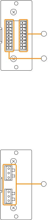
7.2.4. C-001T (Control I/O Expansion Module)
The C-001T module is designed for use with the 9000M2 Series amplifiers and can provide up to 8 channels each of input and output expansion.
Since the main unit has 4 fixed inputs and outputs each, the control input and output can be expanded to up to 12 channels each when the C-001T module is used.
|
C-001T |
|
7. Control input terminal [IN 1, 2, 3, 4, 5, 6, 7, 8, E] |
|
|
|
9-pin removable terminal block, 8-circuit control input terminal. |
|
|
|
Individual input functions are assigned on the front panel setting screen |
OUT |
IN |
|
of the main unit. |
|
1 |
|
|
|
2 |
|
|
|
3 |
|
8. Control output terminal [OUT 1, 2, 3, 4, 5, 6, 7, 8, E] |
|
4 |
7 |
|
|
5 |
9-pin removable terminal block, 8-circuit control output terminal. |
|
|
6 |
|
|
|
|
Individual output functions are assigned on the front panel setting screen |
|
|
7 |
|
|
|
8 |
|
of the main unit. |
|
E |
|
8
7.2.5. AN-001T (Ambient Noise Sensor Input Module)
The AN-001T module is designed for use with the 9000M2 Series amplifiers and automatically adjusts the amplifier's output volume in response to the change in ambient noise level.
Maximum 2 AN-001T modules (4 channels in total) can be used per 9000M2 Series amplifier.
It can handle signals from microphone level (–60 dB) to line level (–10 dB) by controlling the gain in 9 steps. Phantom power (+24 V) can be supplied to a condenser microphone.
The AN-001T's inputs are for detecting ambient noise level and cannot be used as normal audio inputs. Ambient noise fed to the inputs can be monitored when the monitor function is set to ON in the Input setting flow.
AN-001T
1
Hot
Cold
Earth
9
2
Hot
Cold
Earth
9.Monaural input terminals [1, 2]
Electronically-balanced 3P removable terminal blocks. Input level: –60 dB to –10 dB selectable.
Input impedance is 10 kΩ when the phantom power is OFF, and 3 kΩ when ON.
20
7.2.6. RC-001T (Remote Control Module)
The RC-001T is an interface module to connect between the 9000M2 Series amplifier and the ZM-9011, ZM9012, ZM-9013, or ZM-9014 Remote Control Panel of data communication type. It allows the control panels to perform paging activation, scene memory change, and input/output volume control.
Up to 16 control panels can be connected to the RC-001T.
Power for the connected control panels is supplied from the AC adapters connected to the RC-001T. One AC adapter is needed every 8 control panels.
The maximum communication cable length between the RC-001T and control panels is max. 800 m (875 yd) in total.
10 |
14 |
|
11 |
||
|
||
12 |
|
|
13 |
15 |
10.Data line connection terminals for Link A
Connect the communication line from up to 8 control panels. Note that the communication line has polarities.
11.24 V DC output terminals for Link A
Supply 24 V DC power to the control panels.
12.Data line connection terminals for Link B
Connect the communication line from up to 8 control panels. Note that the communication line has polarities.
13.24 V DC output terminals for Link B
Supply 24 V DC power to the control panels.
14.AC adapter input terminal for Link A
Connects the AC adapter for supplying DC power to the control panels of LINK A.
15.AC adapter input terminal for Link B
Connects the AC adapter for supplying DC power to the control panels of LINK B.
21
7.3. Optional Accessories
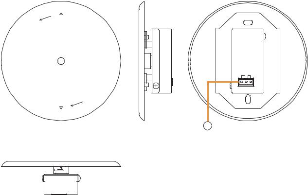
7.3.1. AN-9001 (Ceiling Mount Microphone)
The AN-9001 is designed to be mounted in a wall or ceiling with the use of a 1-gang electrical box.
It is used in conjunction with the AN-001T Ambient Noise Sensor Input module in the 9000M2 Series system.
[Front] |
[Side] |
[Rear] |
|
Release |
|
Hot Cold Earth
Lock
1 |
[Bottom]
1.Microphone output terminal [Hot, Cold, Earth]
Electronically-balanced 3P removable terminal block.
Sensitivity: –5 dB (1 kHz, 0 dB=1 V/Pa)
Output impedance: 200 Ω
Note
In designing the layout of the AN-9001, pay particular attention to the following points so that the AN-9001 and AN-001T in combination can function effectively.
•Position the AN-9001 fully away from the speaker to be used for zone announcement. Doing otherwise may cause the AN-9001 to detect the speaker sound as noise, failing to keep the optimum sound level.
•Do not position the AN-9001 near the equipment that constantly generates loud noise. If positioned, the AN9001 will respond to such loud noise, failing to respond to the change in ambient noise level.
22
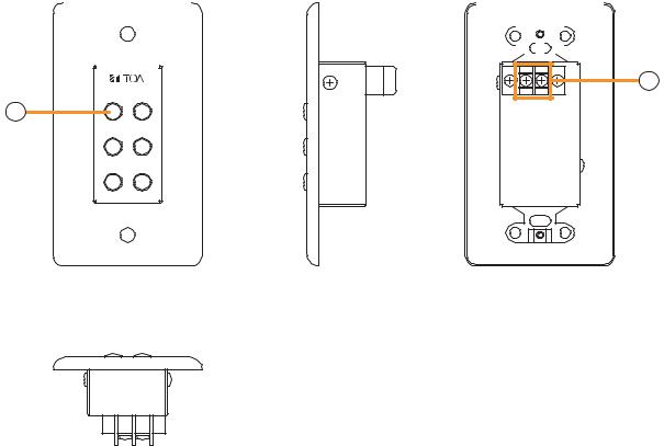
7.3.2. ZM-9001 (Zone Manager)
The ZM-9001 adds 6 control inputs and can be mounted in a 1-gang electrical box.
[Front] |
[Side] |
[Rear] |
||||||||||||||
|
|
|
|
|
|
|
|
|
|
|
|
|
|
|
|
|
|
|
|
|
|
|
|
|
|
|
|
|
|
|
|
|
|
|
|
|
|
|
|
|
|
|
|
|
|
|
|
|
|
|
|
|
|
|
|
|
|
|
|
|
|
|
|
|
|
|
|
|
|
|
|
|
|
|
|
|
|
|
|
|
|
|
|
|
|
|
|
|
|
|
|
|
|
|
|
|
|
|
|
|
|
|
|
|
|
|
|
|
|
|
|
|
|
|
|
|
|
|
|
|
|
|
|
|
|
|
|
|
|
|
|
|
|
|
|
3
1 |
2 |
2 |
E OUT |
|
34
5 6
[Bottom]
2.Control buttons [1 – 6]
Activate the function assigned to them when pressed.
3.Control output terminal [E, OUT]
Connect this terminal to the 9000M2 Series amplifier's REMT VOL terminal.
Use a shielded cable with 50 Ω or less line resistance (per line) for this connection. Avoid installation of this cable and power cables in the same conduit. Separate piping.
23
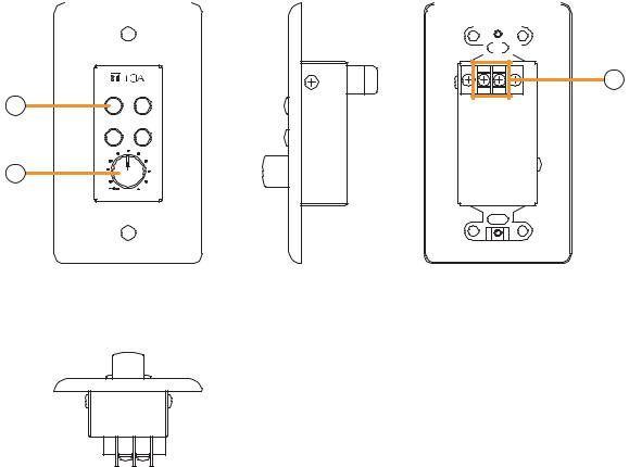
7.3.3. ZM-9002 (Zone Manager)
The ZM-9002 adds 4 control inputs and 1 volume control, and can be mounted in a 1-gang electrical box.
[Front] |
[Side] |
[Rear] |
||||||||||
|
|
|
|
|
|
|
|
|
|
|
|
|
|
|
|
|
|
|
|
|
|
|
|
|
|
|
|
|
|
|
|
|
|
|
|
|
|
|
|
|
|
|
|
|
|
|
|
|
|
|
|
|
|
|
|
|
|
|
|
|
|
|
|
|
|
|
|
|
|
|
|
|
|
|
|
|
|
6
1 |
2 |
4 |
E OUT |
|
34
5
 0
0
[Bottom]
4.Control buttons [1 – 4]
Activate the function assigned to them when pressed.
5.Volume control
Adjusts the volume on the assigned input or output channel.
6.Control output terminal [E, OUT]
Connect this terminal to the 9000M2 Series amplifier's REMT VOL terminal.
Use a shielded cable with 50 Ω or less line resistance (per line) for this connection. Avoid installation of this cable and power cables in the same conduit. Separate piping.
24
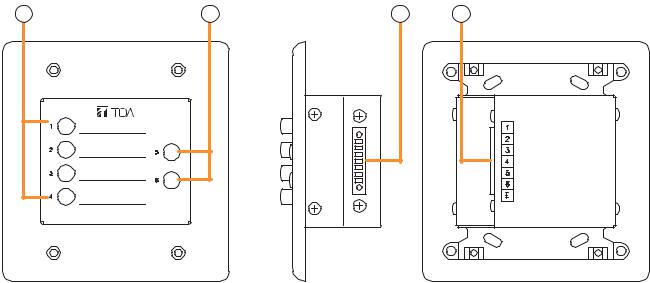
7.3.4. ZM-9003 (Zone Manager)
The ZM-9003 is a remote control switch panel with 4 control selection buttons and 2 control buttons. Connecting it to the 9000M2 Series amplifier's control input terminal permits various controls such as BGM source selection and the sound volume adjustment.
It can be mounted in an American standard 2-gang electrical box in a wall.
[Front] |
|
[Side] |
[Rear] |
7 |
8 |
9 |
9 |
7.Control selection buttons (Interlocking selection switches) [1 – 4]
Activate the function assigned to them when pressed.
8.Control buttons (Momentary switches) [5, 6]
Activate the function assigned to them when pressed.
9.Control output terminal [1 – 6, E]
Connect this terminal to the 9000M2 Series amplifier's control input terminal. Use a cable with 250 Ω or less line resistance (per line) for this connection.
Avoid installation of this cable and power cables in the same conduit. Separate piping.
25
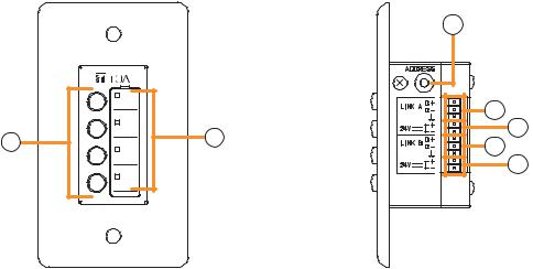
7.3.5. ZM-9011 (Remote Control Panel)
Designed to be connected to the RC-001T, the ZM-9011 is equipped with 4 buttons to perform various controls.
The in-use indicators turn on or off synchronizing with the amplifier operation through data communications between the ZM-9011 and the RC-001T.
It can be mounted in an American standard 1-gang electrical box.
|
[Front] |
[Side] |
|
|
12 |
|
|
13 |
10 |
11 |
14 |
13 |
||
|
|
14 |
10.Control buttons
Activate the function assigned to them when pressed.
Functions to be assigned to these buttons are paging ON/OFF, cross point ON/OFF, scene switching, and control output.
11.In-use indicators
Light when the function assigned to the button pressed is activated.
It goes off automatically after the button operation if the function in operation is activated by higher priority equipment or reset by other equipment.
12.Address selector [0 – F]
Sets the ZM-9011 address.
Be sure to set the different address among other remote control panels.
Addresses are arranged numerically (0 – 9), and alphabetically (A – F) in this order.
13.Data terminals [LINK A/B D+, D–]
Connect the communication line to the RC-001T.
As the communication line has polarities, match both polarities of the ZM-9011 and the RC-001T when connected.
Each 2 identical terminals is provided, and the identical terminals are internally connected to one another. Either set of terminals can be used for connection to other controller.
14.24 V DC input terminals [24 V +, –]
Connect the DC power cable from the RC-001T.
Each 2 identical terminals is provided, and the identical terminals are internally connected to one another. Either set of terminals can be used for connection to other controller.
26
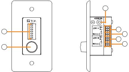
7.3.6. ZM-9012 (Remote Control Panel)
Designed to be connected to the RC-001T, the ZM-9012 is equipped with a volume control knob to perform the volume level setting on the set input or output channel.
The indicators show the volume level set by the volume control knob, that is the volume control knob position. It can be mounted in an American standard 1-gang electrical box.
[Front] |
[Side] |
|
|
17 |
|
15 |
18 |
|
19 |
||
|
||
|
18 |
|
16 |
19 |
|
|
15.Set volume level indicators
Indicate the volume level set by the volume control knob (16). The set levels are shown by 7-point LED indicators, each of which shows -30 dB, -20 dB, -10 dB, -5 dB, 0 dB, +5 dB, and +10 dB from the bottom.
16.Volume control
Adjusts the volume level of input or output channel.
17.Address selector [0 – F]
Sets the ZM-9012 address.
Be sure to set the different address among other remote control panels.
Addresses are arranged numerically (0 – 9), and alphabetically (A – F) in this order.
18.Data terminals [LINK A/B D+, D–]
Connect the communication line to the RC-001T.
As the communication line has polarities, match both polarities of the ZM-9012 and the RC-001T when connected.
Each 2 identical terminals is provided, and the identical terminals are internally connected to one another. Either set of terminals can be used for connection to other controller.
19.24 V DC input terminals [24 V +, –]
Connect the DC power cable from the RC-001T.
Each 2 identical terminals is provided, and the identical terminals are internally connected to one another. Either set of terminals can be used for connection to other controller.
27

7.3.7. ZM-9013 (Remote Control Panel)
Designed to be connected to the RC-001T, the ZM-9013 is equipped with 8 buttons to perform various controls.
The in-use indicators turn on or off synchronizing with the amplifier operation through data communications between the ZM-9013 and the RC-001T.
It can be mounted in an American standard 2-gang electrical box.
[Front] |
|
|
|
[Side] |
20 |
21 |
20 |
21 |
22 |
|
|
|
|
23 |
|
|
|
|
24 |
|
|
|
|
23 |
|
|
|
|
24 |
20.Control buttons
Activate the function assigned to them when pressed.
Functions to be assigned to these buttons are paging ON/OFF, cross point ON/OFF, scene switching, and control output.
21.In-use indicators
Light when the function assigned to the button pressed is activated.
It goes off automatically after the button operation if the function in operation is activated by higher priority equipment or reset by other equipment.
22.Address selector [0 – F]
Sets the ZM-9013 address.
Be sure to set the different address among other remote control panels.
Addresses are arranged numerically (0 – 9), and alphabetically (A – F) in this order.
23.Data terminals [LINK A/B D+, D–]
Connect the communication line to the RC-001T.
As the communication line has polarities, match both polarities of the ZM-9013 and the RC-001T when connected.
Each 2 identical terminals is provided, and the identical terminals are internally connected to one another. Either set of terminals can be used for connection to other controller.
24.24 V DC input terminals [24 V +, –]
Connect the DC power cable from the RC-001T.
Each 2 identical terminals is provided, and the identical terminals are internally connected to one another. Either set of terminals can be used for connection to other controller.
28
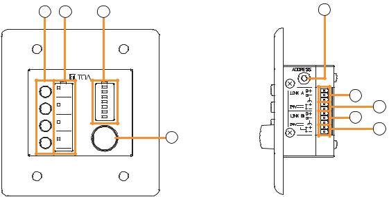
7.3.8. ZM-9014 (Remote Control Panel)
Designed to be connected to the RC-001T, the ZM-9014 is equipped with 4 buttons to perform various controls and a volume control knob to perform the volume level setting on the set input or output channel. The indicators show the volume level for a channel set by the volume control knob, that is the volume control knob position.
It can be mounted in an American standard 2-gang electrical box.
[Front] |
|
|
[Side] |
25 |
26 |
27 |
29 |
|
|
|
30 |
|
|
|
31 |
|
|
|
30 |
|
|
|
31 |
|
|
|
28 |
25.Control buttons
Activate the function assigned to them when pressed.
26.In-use indicators
Light when the function assigned to the button pressed is activated.
It goes off automatically after the button operation if the function in operation is activated by higher priority equipment or reset by other equipment.
27.Set volume level indicators
Indicate the volume level set by the volume control knob (28). The set levels are shown by 7-point LED indicators, each of which shows –30 dB, –20 dB, –10 dB, –5 dB, 0 dB, +5 dB, and +10 dB from the bottom.
28.Volume control
Adjusts the volume level of input or output channel.
29.Address selector [0 – F]
Sets the ZM-9014 address.
Be sure to set the different address among other remote control panels.
Addresses are arranged numerically (0 – 9), and alphabetically (A – F) in this order.
30.Data terminals [LINK A/B D+, D–]
Connect the communication line to the RC-001T.
As the communication line has polarities, match both polarities of the ZM-9014 and the RC-001T when connected.
Each 2 identical terminals is provided, and the identical terminals are internally connected to one another. Either set of terminals can be used for connection to other controller.
31.24 V DC input terminals [24 V +, –]
Connect the DC power cable from the RC-001T.
Each 2 identical terminals is provided, and the identical terminals are internally connected to one another. Either set of terminals can be used for connection to other controller.
29

Function buttons and indicators on the ZM-9011, ZM-9013, and ZM-9014
The lighting mode of the operation indicator differs depending on the function assigned to the Function button. When a communication error occurs between these remote control panels and the RC-001T module, the lighting mode differs from that in the normal state regardless of the function assigned to the button. The respective lighting modes are as follows.
[When the paging function is assigned to the Function button]
The indicator lights when the paging is activated by pressing the Function button. In this event, it flashes if paging call cannot be made because the higher-priority broadcast is in progress, and switches to steady-on once paging call access is enabled after the higher-priority broadcast completion.
•At the time of paging activation (When no priority broadcast is made)
Lit
(When priority broadcast is in progress)
Flash
The indicator goes off when the paging call is completed by
• At the time of paging termination
pressing the button again.
Unlit
[When the cross point ON/OFF function is assigned to the Function button]
The indicator lights when the cross point function is enabled by pressing the Function button, and goes off when turned OFF by pressing the button again.
(When set to ON) Lit
(When set to OFF) Unlit
[When the scene recall function is assigned to the Function button]
The indicator lights when the preset scene is recalled by pressing the Function button, and goes off when switched over to other scene from other devices.
(When the scene is recalled) Lit
(When other scene is recalled from other devices)
Unlit
[When the contact control output function is assigned to the Function button]
The indicator lights when the set contact control output is turned ON by pressing the Function button.
When the button operation is set to momentary type, the output turns on and also the indicator lights as long as the button is pressed. When the button operation is set to alternate type, the output alternates between ON and OFF each time the button is pressed and the indicator cycles between ON (lit) and OFF (unlit) as well.
[When a communication error occurs]
The operation indicator goes off.
When the Function button is pressed, the indicator lights briefly, Unlit then goes off.
30
 Loading...