


SETTING SOFTWARE INSTRUCTIONS
INTEGRATED VOICE EVACUATION SYSTEM
VM-3000 Series
VOICE ALARM SYSTEM AMPLIFIER 240W |
VM-3240VA |
VOICE ALARM SYSTEM AMPLIFIER 360W |
VM-3360VA |
VM EXTENSION AMPLIFIER 240W |
VM-3240E |
VM EXTENSION AMPLIFIER 360W |
VM-3360E |
FIREMAN'S MICROPHONE |
RM-300MF |
FIREMAN'S MICROPHONE EXTENSION |
RM-320F |
REMOTE MICROPHONE |
RM-200M |
REMOTE MICROPHONE EXTENSION |
RM-210 |
1438
TOA Electronics Europe GmbH
Suederstrasse 282, 20537 Hamburg, Germany
10
1438/CPD/0180
EN 54-16: 2008
Voice alarm control and indicating equipment for fire detection and fire alarm systems VM-3000
Provided options:
7.3Audible warning
7.6.2Manual silencing of the voice alarm condition
7.7.2Manual reset of the voice alarm condition
7.9Voice alarm condition output
8.3 Indication of faults related to voice alarm zones
10Voice alarm manual control
11Interface to external control device(s)
12Emergemcy microphone(s)
13.14 Redundant power amplifiers
Technical data: see document VM-3000 Instruction Manual
Thank you for purchasing TOA's VM-3000 Series System.
Please carefully follow the instructions in this manual to ensure long, trouble-free use of your equipment.
TABLE OF CONTENTS |
|
|
1. |
SOFTWARE OUTLINE ...................................................................................... |
4 |
2. |
NOTES ON PERFORMING SETTINGS |
|
|
2.1. System Requirements ........................................................................................ |
5 |
|
2.2. Notes |
|
|
2.2.1. Displays .................................................................................................... |
5 |
|
2.2.2. Window screens........................................................................................ |
5 |
3. |
SOFTWARE SETUP |
|
|
3.1. Setting Software Installation ............................................................................... |
6 |
|
3.2. Uninstallation....................................................................................................... |
8 |
|
3.3. Update................................................................................................................. |
9 |
4. |
RUNNING THE VM-3000 SETTING SOFTWARE .................................. |
10 |
5. |
SETTING ITEMS ............................................................................................... |
11 |
|
5.1. Menu Structure ................................................................................................. |
12 |
|
5.2. Menu Bar Items & Explanations........................................................................ |
13 |
6. |
SYSTEM SETTINGS......................................................................................... |
14 |
|
6.1. System Type Settings ...................................................................................... |
15 |
|
6.2. Setting the Number of VM-3000Es ................................................................... |
17 |
|
6.3. Settings for RM-300MF & RM-200M Remote Microphones.............................. |
18 |
|
6.4. External ATT Settings ....................................................................................... |
19 |
|
6.5. End of Line (EOL) Unit Settings ........................................................................ |
21 |
|
6.6. VM-3000VA Settings......................................................................................... |
22 |
|
6.6.1. Audio input settings................................................................................. |
23 |
|
6.6.2. Audio output settings .............................................................................. |
24 |
|
6.6.3. Control input settings .............................................................................. |
25 |
|
6.6.4. Control output settings ............................................................................ |
26 |
|
6.6.5. VM-3000VA/VM-3000E setting screen changeover ............................... |
27 |
|
6.6.6. Returning to the system setting screen from the |
|
|
VM-3000VA setting screen ..................................................................... |
28 |
|
6.7. VM-3000E Settings ........................................................................................... |
29 |
|
6.7.1. Audio output setting ................................................................................ |
30 |
|
6.7.2. Control input settings .............................................................................. |
31 |
|
6.7.3. Control output settings ............................................................................ |
32 |
|
6.7.4. VM-3000VA/VM-3000E setting screen changeover ............................... |
33 |
|
6.7.5. Returning to the system setting screen from the |
|
|
VM-3000E setting screen........................................................................ |
34 |
|
6.8. Local Input Setting ............................................................................................ |
35 |
7. |
SURVEILLANCE SETTINGS ........................................................................ |
36 |
|
7.1. Time/Interval Setting ......................................................................................... |
37 |
|
7.2. Surveillance Group Settings.............................................................................. |
38 |
8. |
PRIORITY SETTINGS ..................................................................................... |
41 |
|
8.1. General Broadcast Sound Source Priority Settings .......................................... |
42 |
|
8.2. Emergency Sound Source Priority Display ....................................................... |
44 |
9. |
ZONE SETTINGS ............................................................................................. |
46 |
2
10. EVENT SETTINGS ........................................................................................... |
47 |
10.1. General Control Input Settings ....................................................................... |
48 |
10.2. Emergency Control Input Settings .................................................................. |
51 |
10.3. RM Function Key Settings............................................................................... |
53 |
10.3.1. RM-300MF settings ........................................................................... |
54 |
10.3.2. RM-320F settings................................................................................ |
56 |
10.3.3. RM-200M settings............................................................................... |
58 |
10.3.4. RM-210 settings.................................................................................. |
60 |
11. LOG DISPLAY ................................................................................................... |
62 |
12. ERROR LIST DISPLAY.................................................................................... |
64 |
13. MENU ITEM OPERATIONS FROM THE MENU BAR |
|
13.1. Creating a New Setting File ............................................................................ |
65 |
13.2. Loading Set Files ............................................................................................ |
67 |
13.3. Saving Set Files |
|
13.3.1. Overwriting an existing file .................................................................. |
69 |
13.3.2. Saving new set files ............................................................................ |
70 |
13.4. Printing Set Data ............................................................................................. |
72 |
13.5. Exporting Printed Data in CSV Format ........................................................... |
74 |
13.6. Printing Remote Microphone Labels ............................................................... |
76 |
13.7. Exiting Setting Software .................................................................................. |
78 |
13.8. Selecting the Setting Software Display Language .......................................... |
79 |
13.9. Network Settings between Setting Software and VM-3000VA........................ |
80 |
13.10. Transferring Data Edited by PC between the VM-3000VA and a PC |
|
13.10.1. Loading set VM-3000VA data into a PC ........................................... |
82 |
13.10.2. Writing PC-edited data into the VM-3000VA..................................... |
83 |
13.11. Transferring EV Message Files between the VM-3000VA and a PC |
|
13.11.1. EV file registration screen transfer operation.................................... |
84 |
13.11.2. Simultaneous EV message registration ............................................ |
88 |
13.11.3. Individual EV message file registration ............................................. |
88 |
13.11.4. Individual EV message file erasure................................................... |
88 |
13.12. Setting Software Version Display.................................................................. |
89 |
3
1. SOFTWARE OUTLINE
This setting software is designed to be installed in a PC and used exclusively for performing the settings necessary for operating the VM-3000 system.
Settings are roughly divided into system configurations, failure detection points, broadcasting sound source priorities, broadcast zones, and function assignment to the control inputs and remote microphone keys. This software also features a Log function that integrates event log data from the VM-3240VA or VM-3360VA into a PC and displays such data, as well as an Error List function that shows discrepancies in set data.
Loading the PC-set data into the VM-3240VA or VM-3360VA allows the VM-3000 system to operate according to the configured settings.
4
2. NOTES ON PERFORMING SETTINGS
2.1. System Requirements
• OS: |
Windows Vista, Windows XP SP2 |
|
• CPU: |
1 |
GHz or faster |
• Memory: |
1 |
GB or more |
|
|
|
Note
Windows and Windows Vista are trademarks of Microsoft Corporation.
2.2. Notes
2.2.1. Displays
The VM-3000 Setting Software creates window displays at a resolution of 1024 x 768 pixels. Setting the screen size to a lower resolution or resizing windows may cause a portion of display to be hidden or cut off.
2.2.2. Window screens
The windows displayed by the VM-3000 Setting Software in this manual are examples and may vary somewhat depending on the specific environment of the PC used.
5
3. SOFTWARE SETUP
Notes
•Close all open applications before installing.
•To install the software, it is necessary to log in to the PC using an administrator account.
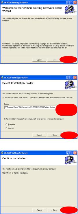
3.1. Setting Software Installation
Step 1. Click on "setup.exe" in the setting software folder contained in the CD supplied with the VM-3240VA and VM-3360VA.
The installation wizard screen is displayed.
Note
The installation wizard screen may not be displayed. In this case, read the next page.
Step 2. Click the Next button.
The Select Installation Folder screen is displayed.
Step 3. Change the folder as needed, then click the Next button.
The Confirm Installation dialog is displayed.
Step 4. Click the Next button to start installing the software.
6
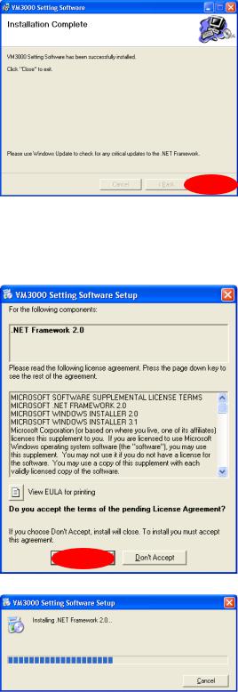
Step 5. When the Installation Complete dialog is displayed, click the Close button to complete the installation.
[If no installation wizard screen is displayed]
The screen at right may be displayed when the Step 1 is performed. In this case, install the software needed to run the VM-3000 Setting Software with the steps below.
Step 1. Click the Accept button.
Installation in progress screen is displayed.
As the installation wizard screen is displayed after completion of installation, follow the steps shown on the previous page.
7
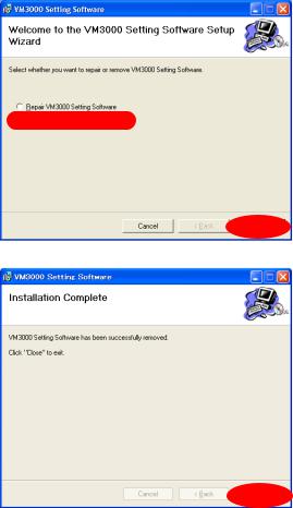
3.2. Uninstallation
Step 1. Click on "setup.exe" in the setting software folder contained in the CD supplied with the VM-3240VA and VM-3360VA.
The setup wizard screen is displayed.
Step 2. Select "Remove VM3000 Setting Software," and click the Finish button to start uninstalling the software.
Step 3. When the Installation Complete dialog is displayed, click the Close button to complete the uninstallation.
8
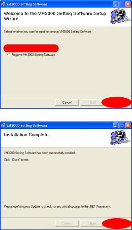
3.3. Update
Step 1. Click on "setup.exe" in the setting software folder contained in the CD supplied with the VM-3240VA and VM-3360VA.
The setup wizard screen is displayed.
Step 2. Select "Repair VM3000 Setting Software," and click the Finish button to start updating the software.
Step 3. When the Installation Complete dialog is displayed, click the Close button to complete the update.
9
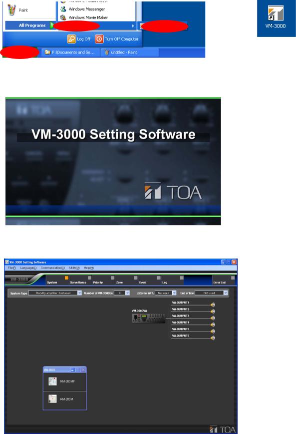
4. RUNNING THE VM-3000 SETTING SOFTWARE
To start the software, select "VM-3000  desktop.
Start menu
Setting Software," or double-click the VM-3000 shortcut icon on the
Shortcut icon on the desktop
Activating the software displays the following splash screen.
After activation is complete, the VM-3000 Setting Software initial screen is displayed.
10
5. SETTING ITEMS
Menu items are displayed at the top of the setting screen.
These menu items include those from "System" to "Event." Settings are conducted in order from left to right. The other two menu items, "Log" and "Error List," are respectively for checking event histories and checking for irregularities in the settings data. Clicking on any of these menu items calls up the relevant setting screen.
Note
In the following setting screen illustrations and instructions, the VM-3240VA and VM-3360VA are referred to collectively as simply "VM-3000VA," and the VM-3240E and VM-3360E are referred to collectively as simply "VM-3000E."
Menu Items
11

5.1. Menu Structure
System |
(p. 14) |
|
|
System Type |
(p. 15) |
||
|
|
||||||
|
|
|
|
|
|
|
|
|
|
|
|
|
|
|
|
|
|
|
|
Number of VM-3000Es |
(p. 17) |
||
|
|
|
|
||||
|
|
|
|
|
|
|
|
|
|
|
|
|
|
|
|
|
|
|
|
RM-300MF |
(p. 18) |
||
|
|
|
|
||||
|
|
|
|
|
|
|
|
|
|
|
|
|
|
|
|
|
|
|
|
RM-200M |
(p. 18) |
||
|
|
|
|
||||
|
|
|
|
|
|
|
|
|
|
|
|
|
|
|
|
|
|
|
|
External ATT. |
(p. 19) |
||
|
|
|
|
||||
|
|
|
|
|
|
|
|
|
|
|
|
|
|
||
|
|
|
|
EOL (End of line) |
(p. 21) |
||
|
|
|
|
||||
|
|
|
|
|
|
|
|
|
|
|
|
|
|
|
|
|
|
|
|
VM-3000VA |
(p. 22) |
||
|
|
|
|
||||
|
|
|
|
|
|
|
|
|
|
|
|
|
|
|
|
|
|
|
|
VM-3000E |
(p. 29) |
||
|
|
|
|
||||
|
|
|
|
|
|
|
|
|
|
|
|
|
|
|
|
|
|
|
|
|
|
Local Input |
(p. 35) |
|
|
|
|
|
|
||
|
|
|
|
|
|
|
|
|
|
|
|
|
|
|
|
Surveillance |
(p. 36) |
|
|
Time/Interval Setting |
(p. 37) |
||
|
|
||||||
|
|
|
|
|
|
||
|
|
|
|
|
|||
|
|
|
|
Surveillance Group Settings(p. 38) |
|||
|
|
|
|
||||
|
|
|
|
|
|
|
|
|
|
|
|
|
|
|
|
Priority |
(p. 41) |
|
|
General Setting |
(p. 42) |
||
|
|
||||||
|
|
|
|
|
|
|
|
|
|
|
|
|
|
|
|
|
|
|
|
Emergency Setting |
(p. 44) |
||
|
|
|
|
||||
|
|
|
|
|
|
|
|
|
|
|
|
|
|
|
|
Zone |
(p. 46) |
|
|
Zone Setting |
(p. 46) |
||
|
|
||||||
|
|
|
|
|
|
|
|
|
|
|
|
|
|
|
|
Event |
(p. 47) |
|
|
General Setting |
(p. 48) |
||
|
|
||||||
|
|
|
|
|
|
|
|
|
|
|
|
|
|
|
|
|
|
|
|
|
|
VM-3000VA |
(p. 48) |
|
|
|
|
|
|
||
|
|
|
|
|
|
|
|
|
|
|
|
|
|
|
|
|
|
|
|
|
|
VM-3000E |
(p. 48) |
|
|
|
|
|
|
||
|
|
|
|
|
|
|
|
|
|
|
|
|
|
|
|
|
|
|
|
Emergency Setting |
(p. 51) |
||
|
|
|
|
||||
|
|
|
|
|
|
|
|
|
|
|
|
|
|
|
|
|
|
|
|
|
|
VM-3000VA |
(p. 51) |
|
|
|
|
|
|
||
|
|
|
|
|
|
|
|
|
|
|
|
|
|
|
|
|
|
|
|
|
|
VM-3000E |
(p. 51) |
|
|
|
|
|
|
||
|
|
|
|
|
|
|
|
|
|
|
|
|
|
|
|
|
|
|
|
RM Key Setting |
(p. 53) |
||
|
|
|
|
||||
|
|
|
|
|
|
|
|
Log |
(p. 62) |
|
|
|
|
Error List |
(p. 64) |
|
|
|
|
RM-300MF |
(p. 54) |
|
|
||
|
|
|
|
|
|
|
|
|
|
RM-200M |
(p. 58) |
|
|
||
|
|
|
|
|
|
|
|
Log Display |
(p. 62) |
||
|
|
|
|
|
|
|
|
Error List Display |
(p. 64) |
||
|
|
|
|
Selects a system configuration from the following options: 1-channel broadcasting (no standby amplifier); 1-channel (with standby amplifier); and 2-channel broadcasting (BGM/paging).
Sets the number of extension amplifiers.
Sets the connection format for the RM-300MF emergency remote microphones.
Sets the connection format for the RM-200M general use remote microphones.
Sets the external attenuator.
Sets EOL units to be connected to the speaker lines.
Sets the names of the audio inputs, audio outputs, control inputs, and control outputs for the VM3240VA/3360VA.
Sets the names of the audio outputs, control inputs, and control outputs for the VM-3240E/3360E.
Sets the local input.
Sets the time and interval for specific surveillance items.
Allocates surveillance items into up to 64 groups.
Sets sound source priorities for general broadcasting.
Displays the priority setting status of emergency broadcasting sound sources.
Sets broadcast zones.
Sets general broadcast control input functions for the VM-3240VA/3360VA.
Sets general broadcast control input functions for the VM-3240E/3360E.
Sets the front panel-mounted emergency broadcast keys' functions, and emergency control input functions for the VM-3240VA/3360VA.
Sets the emergency control input functions for the VM3240E/3360E.
Sets the RM-300MF function display and RM-320F key functions.
Sets RM-200M and RM-210 key functions.
Displays event history information and stores history data.
Displays a list of errors and other irregularities occurring within set data.
12
5.2. Menu Bar Items & Explanations
For details on operations conducted by selecting the following menu items from the menu bar, see "Menu Item Operations from the Menu Bar" on page 65.
File (F) |
|
|
|
|
|
New (N): |
Creates a new data file to be used by the VM-3000 setting software. |
|
Open (O): |
Reads an existing data file to be used by the VM-3000 setting software. |
|
Save (S): |
Saves the information currently being edited by the VM-3000 setting software |
|
|
|
and overwrites an existing data. |
Save As (A): |
Saves the information currently being edited by the VM-3000 setting software |
|
|
|
under a new file name. |
Data Output (P) |
|
|
Print Setting Data (P): |
Prints setting data. |
|
CSV Output (C): |
Exports setting data as a CSV file. |
|
RM Label (L): |
Creates and prints labels used to identify the keys on remote microphones (RM- |
|
|
|
300MF, RM-320F, RM-200M, and RM-210). |
Exit (X): |
Quits the VM-3000 setting software. |
|
|
|
|
Language (L) |
|
|
|
|
|
Select (S): |
Selects the display language used by the VM-3000 setting software. |
|
|
|
|
Communication (C) |
|
|
|
|
|
Setting Data: VA->PC (D): |
Allows PC-set data stored in the VM-3240VA/3360VA to be read back into a PC. |
|
Setting Data: PC->VA(U): |
Allows data set on a PC to be written from the PC into the VM-3240VA/3360VA. |
|
Network Setting(N): |
Conducts communication settings needed to achieve communication between |
|
|
|
the VM-3000 setting software and the VM-3240VA/3360VA. |
|
|
|
Utility (U) |
|
|
|
|
|
EV (E): |
Allows EV message sound source files used by the VM-3240VA/3360VA to be |
|
|
|
written into the VM-3240VA/3360VA from a PC or read from the VM- |
|
|
3240VA/3360VA to a PC. |
|
|
|
Help (H) |
|
|
|
|
|
Version (A): |
Displays the version information for the VM-3000 setting software. |
|
13
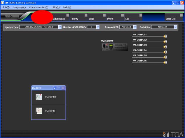
6. SYSTEM SETTINGS
Set the system configuration and inputs and outputs for each device. Click the Menu item "System" button to display the system setting screen.
14
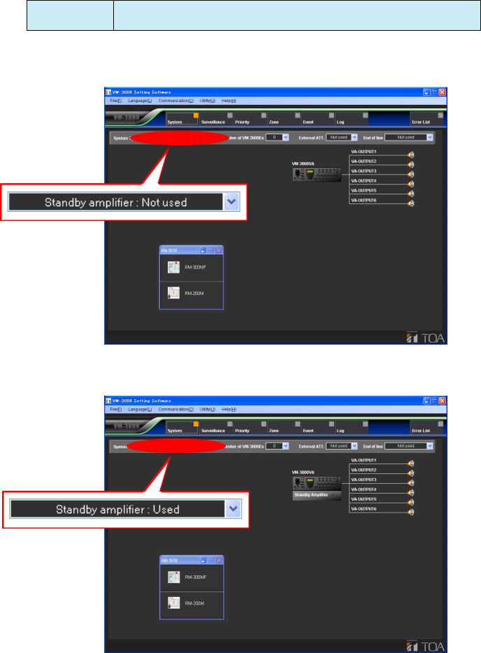
6.1. System Type Settings
Select the type of VM-3000 system.
Available Settings Standby amplifier: Not used (default), Standby amplifier: Used, BGM/PAGING System
Setting this to "Standby amplifier: Not used" sets the configuration to a system that does not use a standby amplifier.
Setting this to "Standby amplifier: Used" sets the configuration to a system that does use a standby amplifier. In such cases, use a VP-2000 series amplifier as the VM-3000VA's standby amplifier.
15
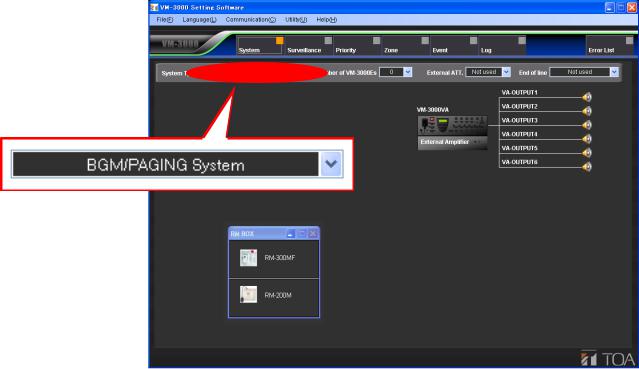
Setting this to "BGM/Paging System" allows connection of a VP-2000 series amplifier to each VM-3000VA and VM-3000E in order to configure simultaneous 2-channel broadcast system for BGM and paging announcement.
In the case of emergency broadcasts, simultaneous 2-channel broadcast of microphone announcements, and pre-recorded Evacuation or Alert announcements is possible.
16
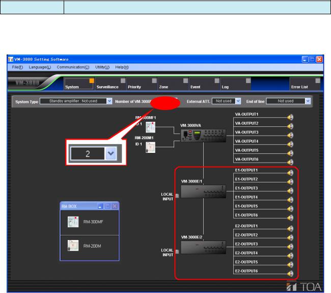
6.2. Setting the Number of VM-3000Es
Set the number of VM-3000Es being used.
Available Settings 0 to 9 (default: 0)
Selecting a number causes the VM-3000E icon to be displayed.
17
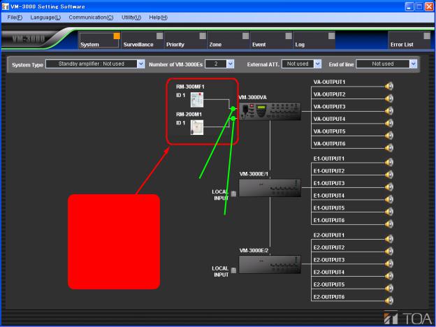
6.3. Settings for RM-300MF & RM-200M Remote Microphones
Set the remote microphones being used.
Select the remote microphones to be used from the "RM BOX" window on the system setting screen, then drag and drop it around the VM-3000VA icon.
Select the remote microphone and drag and drop it here.
RM1 LINK IN
RM 2 LINK IN
Clicking the set remote microphone icon transfers the display to the RM Key Setting screen (page 53) in Event Settings, allowing the functions of the remote microphone keys to be set.
To delete a set remote microphone icon, position the pointer on it and right click to access the "Delete" option.
18
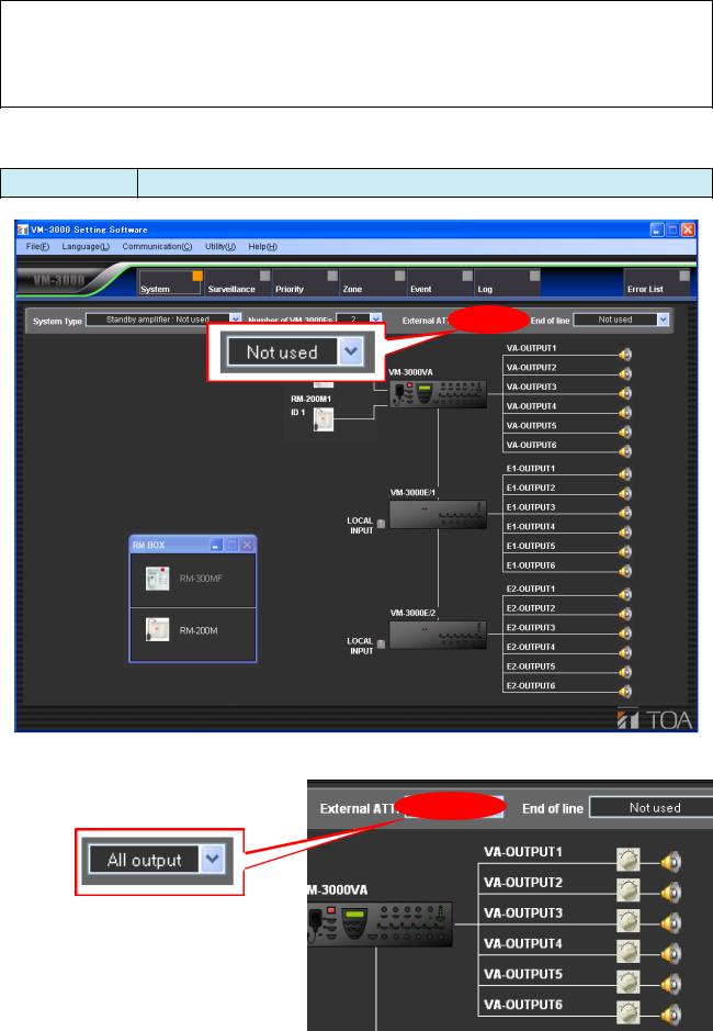
6.4. External ATT Settings
Notes
•This function can be used only when all the versions of VM-3000VA firmware, VM-3000E firmware, and VM-3000 Setting Software are 2.00 or later.
•Both of external attenuators and the EOL unit (refer to page 21) cannot be used together in the same system.
Set whether or not an external attenuator is being used.
Available Settings Not used (default), All output, Each output
Setting this to “All output” causes the speaker lines to be displayed as shown at right.
19
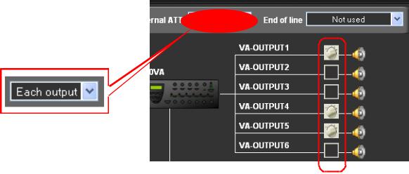
Setting this to “Each output” causes the speaker lines to be displayed as shown at right.
Each attenuator or OFF (not clicked.
20
6.5. End of Line (EOL) Unit Settings
Notes
•This function can be used only when all the versions of VM-3000VA firmware, VM-3000E firmware, and VM-3000 Setting Software are 2.00 or later.
•Both of external attenuators (refer to page 19) and the EOL unit cannot be used together in the same system.
The EOL unit installed at the end of speaker line monitors the presence or absence of a 40 Hz pilot tone from the VM-3000. If the line failure occurs, contact information is sent from the EOL to the VM-3000’s emergency control input, informing the VM-3000 of the abnormality condition.
(The VM-3000’s emergency control input should be set. See page 51, Emergency Control Input Settings.)
If the End of line setting is changed on the system setting screen, the emergency control input should also be changed.
Set the End of line item to “Each output” on the system setting screen as shown below.
Note
The following dialog is displayed after the EOL setting completion. Click “Yes,” then perform the emergency control input setting in the Event settings referring to page 51.
21

6.6. VM-3000VA Settings
Set the audio inputs and outputs, as well as control inputs and outputs, for the VM-3000VA.
Clicking the VM-3000VA icon on the System Setting screen switches the display to the VM-3000VA setting screen.
VM-3000VA
Click the VM-3000VA icon.
"VM-3000VA Setting Screen" |
|
|
|
Changeover to the VM-3000VA/VM-3000E setting |
||||||||||
|
|
|
|
|
|
|
screen (p. 27) |
|
|
|||||
|
|
|
|
|
|
|
|
|||||||
|
Audio input setting (p. 23) |
|
|
|
|
Audio output setting (p. 24) |
|
|
||||||
|
|
|
|
|
|
|
|
|
|
|
|
|
|
|
|
|
|
|
|
|
|
|
|
|
|
|
|
|
|
|
|
|
|
|
|
|
|
|
|
|
|
|
|
|
|
|
|
|
|
|
|
|
|
|
|
|
|
|
|
|
|
|
|
|
|
|
|
|
|
|
|
|
|
|
|
|
|
|
|
|
|
|
|
|
|
|
|
|
|
|
|
|
|
|
|
|
|
|
|
|
|
|
|
|
|
|
|
|
|
|
|
|
|
|
|
|
|
|
|
|
|
|
|
|
|
|
|
|
|
|
|
|
|
|
|
|
|
|
|
|
|
|
|
|
|
|
|
|
|
Control input setting (p. 25) |
Control output setting (p. 26) |
22
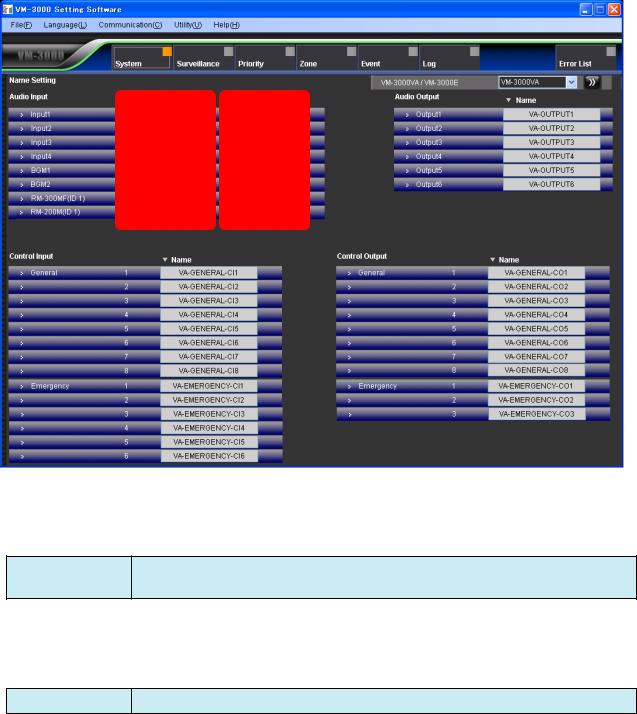
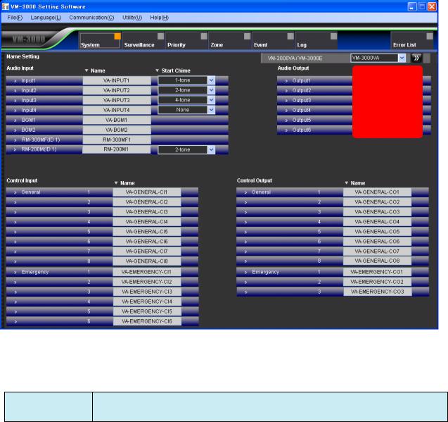
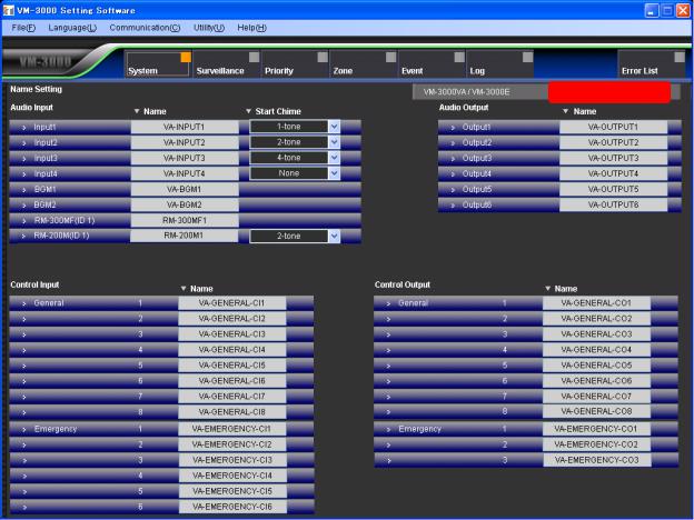
6.6.1. Audio input settings
Set the audio inputs for the VM-3000VA.
(1)(2)
(1)Name
Sets each audio input name.
Available Settings Up to 16 alphanumeric characters (default names are VA-INPUT*, VA-BGM*, RM300MF*, and RM-200M*, in which "*" is a number).
(2)Start Chime
Selects the chime sound used at the beginning of audio input broadcasting.
Available Settings None (default), 1-tone, 2-tone, 4-tone, Gong
23
6.6.2. Audio output settings
Set the audio outputs for the VM-3000VA.
(1)
(1)Name
Sets each audio output name.
Available Settings Up to 16 alphanumeric characters (default name is VA-OUTPUT*, in which "*" is the terminal number).
24
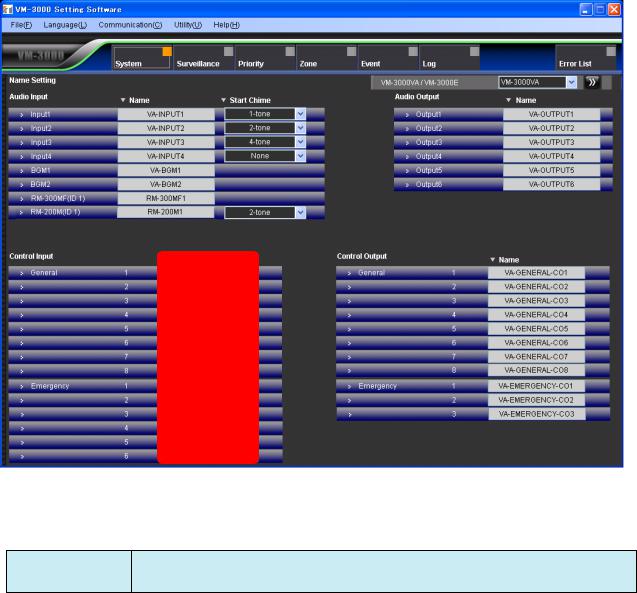
6.6.3. Control input settings
Set the control inputs for the VM-3000VA.
(1)
(1)Name
Sets the names for general and emergency control inputs.
Available Settings Up to 16 alphanumeric characters (default names are VA-GENERAL-CI* and VA- EMERGENCY-CI*, in which "*" is the terminal number).
25
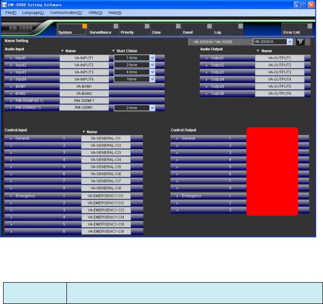
6.6.4. Control output settings
Set the control outputs for the VM-3000VA.
(1)
(1)Name
Sets the names for general control outputs and status outputs.
Available Settings Up to 16 alphanumeric characters (default names are VA-GENERAL-CO* and VA- EMERGENCY-CO*, in which "*" is the terminal number).
26
6.6.5. VM-3000VA/VM-3000E setting screen changeover
Click the box or double-arrow button to select the VM-3000VA or VM-3000E to be set. This will cause the display to change to the setting screen for the selected model.
See page 29 for VM-3000E settings.
27
 Loading...