


OPERATION MANUAL
INTEGRATED VOICE EVACUATION SYSTEM
VM-3000 Series
VOICE ALARM SYSTEM AMPLIFIER |
VM-3240VA |
VOICE ALARM SYSTEM AMPLIFIER |
VM-3360VA |
VM EXTENSION AMPLIFIER |
VM-3240E |
VM EXTENSION AMPLIFIER |
VM-3360E |
FIREMAN’S MICROPHONE |
RM-300MF |
FIREMAN’S MICROPHONE EXTENSION |
RM-320F |
REMOTE MICROPHONE |
RM-200M |
REMOTE MICROPHONE EXTENSION |
RM-210 |
END OF LINE UNIT |
VM-300SV |
1438
TOA Electronics Europe GmbH
Suederstrasse 282, 20537 Hamburg, Germany
10
1438/CPD/0180
EN 54-16: 2008
Voice alarm control and indicating equipment for fire detection and fire alarm systems VM-3000
Provided options:
7.3Audible warning
7.6.2Manual silencing of the voice alarm condition
7.7.2Manual reset of the voice alarm condition
7.9Voice alarm condition output
8.3 Indication of faults related to voice alarm zones
10Voice alarm manual control
11Interface to external control device(s)
12Emergency microphone(s)
13.14 Redundant power amplifiers
Technical data: see document VM-3000 Instruction Manual
(Does not apply to VM-3240VA SA, VM-3360VA SA, VM-3240E SA and VM-3360E SA)
Note: Refer to the Instruction Manual attached to the VX-2000DS for the installation of the the VX2000DS Emergency power supply, the VX-2000PF Power supply frame, and the VX-200PS Power supply unit.
Thank you for purchasing TOA Integrated Voice Evacuation System VM-3000 Series.
Please carefully follow the instructions in this manual to ensure long, trouble-free use of your equipment.
TABLE OF CONTENTS |
|
1. GENERAL DESCRIPTION .............................................................................. |
6 |
2. FEATURES ............................................................................................................ |
6 |
3. SYSTEM CONFIGURATION |
|
3.1. System Example 1 ............................................................................................. |
7 |
3.2. System Example 2 .............................................................................................. |
8 |
3.3. System Example 3 .............................................................................................. |
9 |
3.4. System Example 4 ............................................................................................ |
10 |
3.5. System Example 5 ............................................................................................ |
11 |
4. NOMENCLATURE AND FUNCTIONS |
|
4.1. VM-3240VA and VM-3360VA Voice Alarm System Amplifiers ........................ |
12 |
4.2. VM-3240E and VM-3360E VM Extension Amplifiers ....................................... |
12 |
4.3. RM-300MF Fireman’s Microphone ................................................................... |
18 |
4.4. RM-320F Fireman's Microphone Extension ..................................................... |
21 |
4.5. RM-200M Remote Microphone ........................................................................ |
22 |
4.6. RM-210 Remote Microphone Extension .......................................................... |
24 |
4.7. VP-2241/2421 Power Amplifiers ...................................................................... |
25 |
4.8. VP-200VX Power Amplifier Input Module ........................................................ |
26 |
4.9. VM-300SV End of Line Unit ............................................................................. |
26 |
5. MAKING GENERAL BROADCASTS |
|
5.1. Making Broadcasts from the VM-3240VA or VM-3360VA |
|
5.1.1. BGM broadcasts ..................................................................................... |
27 |
5.1.2. Microphone announcements .................................................................. |
28 |
5.2. Broadcasting from the RM-200M |
|
5.2.1. Microphone announcements .................................................................. |
30 |
5.2.2. Automatic announcement broadcasts .................................................... |
31 |
5.3. Making Automatic Announcements Using Control Signal Inputs ..................... |
32 |
5.4. Summary of General Broadcast Procedures |
|
5.4.1. Making general broadcast from the VM-3240VA or VM-3360VA .......... |
33 |
5.4.2.Making general broadcasts from the RM-200M Remote Microphone ... 33
5.4.3.Broadcasting automatic general announcements
using the control signal input ................................................................. |
33 |
6. MAKING EMERGENCY BROADCASTS .................................................. |
34 |
6.1. Making Emergency Broadcasts from the VM-3240VA or VM-3360VA |
|
6.1.1. Microphone announcements .................................................................. |
35 |
6.1.2. Automatic emergency announcement broadcasts ................................. |
37 |
6.2. Making RM-300MF Emergency Broadcasts |
|
6.2.1. Microphone announcements .................................................................. |
39 |
6.2.2. Automatic emergency announcement broadcasts ................................. |
41 |
6.3. Making Automatic Emergency Announcements Using Control Signal Inputs |
|
(Automatic Fire Alarm Systems, etc.) ............................................................... |
43 |
6.4. Summary of Emergency Broadcast Procedures |
|
6.4.1. Making emergency broadcast from the VM-3240VA or VM-3360VA ..... |
45 |
6.4.2. Fireman’s microphone emergency broadcasts ...................................... |
45 |
6.4.3. Making automatic emergency announcements |
|
using the control signal input ................................................................. |
45 |
2
7. EQUIPMENT STATUS AND RESPONSE WHEN EMERGENCY MODE IS ACTIVATED BY EXTERNAL EQUIPMENT
7.1. RM-300MF Status and Operation When Emergency-Activated |
|
by External Equipment ..................................................................................... |
46 |
7.2. VM-3240VA or VM-3360VA Status and Operation |
|
When Emergency-Activated by External Equipment ........................................ |
46 |
7.3. When Emergency-Activated by External Contact Input |
|
from Automatic Fire Alarm Systems, etc. ......................................................... |
46 |
8. PRIORITY SETTINGS |
|
8.1. General Broadcast Priorities ............................................................................ |
47 |
8.2. Emergency Broadcast Priorities ....................................................................... |
48 |
9. CPU OFF FUNCTION |
|
9.1. What Is the CPU OFF Function? ..................................................................... |
49 |
9.2. Making All-Zone Calls Using the CPU OFF Function |
|
9.2.1. Making all-zone calls from the VM-3240VA or VM-3360VA ................... |
49 |
9.2.2. Making all-zone calls from the RM-300MF |
|
using the CPU OFF function .................................................................. |
49 |
9.3. Priorities When All-Zone Calls Are Made Using the CPU OFF Function ......... |
50 |
10. SURVEILLANCE |
|
10.1. What Is the Surveillance Function? ................................................................ |
51 |
10.2. How to Use the Surveillance Function ........................................................... |
51 |
10.3. Monitored VM-3000 System Components ..................................................... |
51 |
10.4. Equipment Operation upon Failure Detection and Recovery Procedure ....... |
52 |
10.4.1. Equipment operation upon failure detection ...................................... |
53 |
10.4.2. Failure acknowledgment .................................................................... |
56 |
10.4.3. Failure reset operation ....................................................................... |
57 |
10.5. Examples of Failures and Their Counter-Operations |
|
10.5.1. Failure example 1: Communications failure ....................................... |
59 |
10.5.2. Failure example 2: Short circuit of speaker line 6 .............................. |
60 |
10.6. LCD Failure Display ....................................................................................... |
62 |
11. SETTINGS |
|
11.1. Keys Used for Settings ................................................................................... |
66 |
11.2. Setting Hierarchical Chart .............................................................................. |
67 |
11.3. Configuration Settings |
|
11.3.1. Configuration settings hierarchical chart ............................................ |
68 |
11.3.2. Password entry .................................................................................. |
69 |
11.3.3. Configuration setting items ................................................................ |
70 |
11.4. Information Settings |
|
11.4.1. Information setting hierarchical chart ................................................. |
79 |
11.4.2. Information setting items .................................................................... |
79 |
11.5. Audio Settings |
|
11.5.1. Audio settings hierarchical chart ........................................................ |
81 |
11.5.2. Audio setting items ............................................................................. |
82 |
11.6. Surveillance Settings |
|
11.6.1. Surveillance setting hierarchical chart ............................................... |
86 |
11.6.2. Surveillance setting items .................................................................. |
86 |
11.7. Inputs 1 – 3 Settings |
|
11.7.1. Inputs 1 – 3 setting hierarchical chart ................................................ |
87 |
11.7.2. Inputs 1 – 3 setting items ................................................................... |
88 |
3
11.8. BGM Settings |
|
11.8.1. BGM setting hierarchical chart............................................................ |
89 |
11.8.2. BGM setting items .............................................................................. |
90 |
12.REMOTE MICROPHONE SETTINGS (RM-300MF, RM-200M)
12.1. DIP Switch Functions
12.1.1. RM-300MF ......................................................................................... |
91 |
12.1.2. RM-200M ........................................................................................... |
91 |
12.2. Unit ID Number Settings |
|
(RM-300MF: Switch 5 operation or RM-200M: Switch 1 and 2 operation) ..... |
92 |
12.3. Compression Settings |
|
(RM-300MF: Switch 6 operation or RM-200M: Switch 6 operation) ............... |
92 |
12.4. Setting the Terminating RM-300MF Unit (RM-300MF: Switch 7 operation) ... |
93 |
12.5. CPU OFF Function Enable/Disable Settings |
|
(RM-300MF: Switch 8 operation) ................................................................... |
93 |
12.6. Talk Key Settings (RM-200M: Switch 4 operation) ........................................ |
93 |
12.7. Maintenance Mode (RM-300MF: Switch 1 operation) .................................... |
93 |
13. INSTALLATION |
|
13.1. Installing the RM-300MF on a Wall ................................................................ |
94 |
13.2. Installing the RM-320F on a Wall ................................................................... |
97 |
13.3. Installing the RM-200M on a Wall .................................................................. |
99 |
13.4. Installing the RM-210 on a Wall ................................................................... |
100 |
13.5. Linking the RM-200M with the RM-210 (For Desktop Mounting) ................. |
101 |
13.6. Creating Remote Microphone Name Labels |
|
13.6.1. Inserting the name label ................................................................... |
102 |
13.6.2. If the name label is not printed correctly .......................................... |
103 |
13.6.3. Dimensional diagram for printing devices ........................................ |
103 |
13.6.4. Pattern paper for hand writing .......................................................... |
104 |
13.7. Installing the VP-200VX Power Amplifier Input Module |
|
in the VP-2241/2421 Power Amplifiers ........................................................ |
106 |
13.8. Rack Mounting ............................................................................................. |
108 |
13.9. Desktop Mounting of the VM Amplifiers ....................................................... |
109 |
14. CONNECTIONS |
|
14.1. Removable Terminal Plug Connection ......................................................... |
110 |
14.2. Audio and Control Connection Example ...................................................... |
111 |
14.3. Remote Microphone Connections |
|
14.3.1. Power supply and limit on the number of remote microphones ....... |
112 |
14.3.2. RM-300MF connection ..................................................................... |
114 |
14.3.3. RM-200M connection ....................................................................... |
116 |
14.3.4. Connections between RM-300MF and RM-200M ............................ |
118 |
14.4. General Control Input Terminal Connections |
|
14.4.1. Controlling functions assigned to the General Control |
|
Input terminals from the external equipment .................................... |
119 |
14.4.2. Using the local input ......................................................................... |
120 |
14.4.3. Example of connection to external equipment ................................. |
121 |
14.5. Emergency Control Input Terminal Connections ......................................... |
122 |
14.5.1. External emergency control equipment connection ......................... |
123 |
14.5.2. Using the Amplifier cut off function ................................................... |
124 |
14.5.3. Connections to detect failures |
|
on the emergency control input lines ................................................ |
125 |
14.6. VM-300SV Connection ................................................................................. |
127 |
4
14.7. Status Output Terminal Connections ........................................................... |
128 |
14.8. Power Amplifier and Speaker Connections |
|
14.8.1. Speaker connection ......................................................................... |
129 |
14.8.2. External attenuator connection (3-wire system) ............................... |
129 |
14.8.3. External attenuator connection (4-wire system) ............................... |
130 |
14.9. Connections between VM and VP Amplifiers ............................................... |
131 |
14.10. Connections between VM Amplifiers ........................................................... |
133 |
14.11. Connecting Power Supply Equipment .......................................................... |
134 |
15. VM-3000 CABLE USAGE TABLE.............................................................. |
138 |
16. SPECIFICATIONS |
|
16.1. VM-3240VA Voice Alarm System Amplifier ................................................ |
140 |
16.2. VM-3360VA Voice Alarm System Amplifier ................................................ |
142 |
16.3. VM-3240E VM Extension Amplifier ............................................................. |
144 |
16.4. VM-3360E VM Extension Amplifier ............................................................. |
145 |
16.5. RM-300MF Fireman’s Microphone .............................................................. |
146 |
16.6. RM-320F Fireman’s Microphone Extension ................................................ |
146 |
16.7. RM-200M Remote Microphone ................................................................... |
147 |
16.8. RM-210 Remote Microphone Extension ..................................................... |
147 |
16.9. VP-2241 Power Amplifier 1 x 240 W ........................................................... |
148 |
16.10. VP-2421 Power Amplifier 1 x 420 W ........................................................... |
149 |
16.11. VP-200VX Power Amplifier Input Module ................................................... |
150 |
16.12. VM-300SV End of Line Unit ......................................................................... |
150 |
5
1. GENERAL DESCRIPTION
The VM-3000 Series Voice Alarm System is an integrated emergency/general announcement broadcast system. The Voice Alarm System Amplifier that plays the central role in the system is available in two models: VM-3240VA (240W) and VM-3360VA (360W). Using these amplifiers in conjunction with the VM-3240E (240W) and VM-3360E (360W) Extension Amplifiers allows larger systems to be built.
2. FEATURES
•The VM-3240VA and VM-3360VA both have 6 speaker outputs. This can be expanded to up to 60 outputs by combining the amplifier with its corresponding extension amplifiers, the VM-3240E or VM-3360E, respectively.
•Set data, log data and other Voice Alarm System Amplifier data can be accessed by way of the Ethernet.
•Up to 4*1 RM-300MF emergency broadcast Fireman’s Microphones and up to 4*1 general broadcast-use RM-200M Remote Microphones (8*1 units in total) can be connected to the Voice Alarm System Amplifier.
*1 These connection numbers are available only when all the versions of VM-3000VA firmware, RM-300MF firmware, and VM-3000 Setting Software are 3.00 or later. When the versions are earlier than 3.00, up to 2 RM-300MFs and up to 2 RM-200Ms can be connected, respectively. Besides, only up to a total of 4 RM-300Ms and RM-200Ms can be connected. Also, if the system is required to meet the requirements of EN54-16, only up to 2 RM-300MFs can be connected.
•The system enables simultaneous 2-channel broadcast of automatic emergency announcement broadcasts and microphone announcements from the RM-300MF VM Fireman's Microphone. Also, 2-channel broadcast*2 of automatic emergency announcement broadcasts is possible.
*2 2-channel broadcast of automatic emergency announcement broadcasts can be made by respective units using the VM-3240VA/3360VA and VM-3240E/3360E.
By connecting an external amplifier to each of the VM-3240VA/3360VA and VM-3240E/3360E, 2-channel broadcasts of automatic emergency announcement broadcasts can be made to individual units' output lines.
This function can be used only when all the versions of VM-3000VA firmware, VM-3000E firmware, and VM-3000 Setting Software are 3.00 or later. This function is compliant with the BS-5839 Part 8.
•Connecting an external standby amplifier (VP-2241 and VP-2421) to both of the Voice Alarm System Amplifier and its Extension Amplifiers VM-3240E and VM-3360E enables background music (BGM)/paging broadcasts. The BGM/paging broadcast refers to simultaneous 2-channel broadcasts that allow paging calls (microphone announcements) to be made over other zones without interrupting current BGM broadcasts.
•For systems employing the VX-2000DS Emergency Power Supply, only emergency broadcasts can be made while backup power is being supplied by the VX-2000DS, even if the main power supply has been cut off.
•Easy-to-understand on-screen settings can be performed from a PC screen using the setting software.
•Audio inputs include inputs 1 – 4, a remote microphone input, an emergency remote microphone input, and BGM inputs 1 & 2 (select either of the two).
•Control inputs and outputs include 6 inputs and 3 status outputs for emergency broadcasts, and 8 inputs and 8 outputs for general broadcasts. By adding extension amplifiers (up to 9 units can be connected), the number can be increased up to 60 inputs for emergency broadcasts and up to 80 inputs and 80 outputs for general broadcasts.
6
3. SYSTEM CONFIGURATION
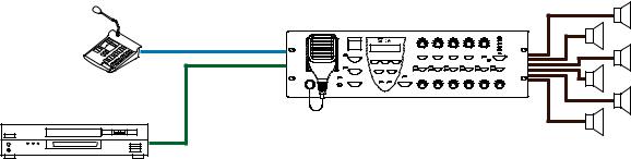
3.1. System Example 1
This example is for one of the simplest systems, and is ideal for installation in restaurants and small stores.
VM-3240VA
RM-200M
BGM unit
[System outline]
• A 240W 1-channel general broadcast system with 6 outputs.
7
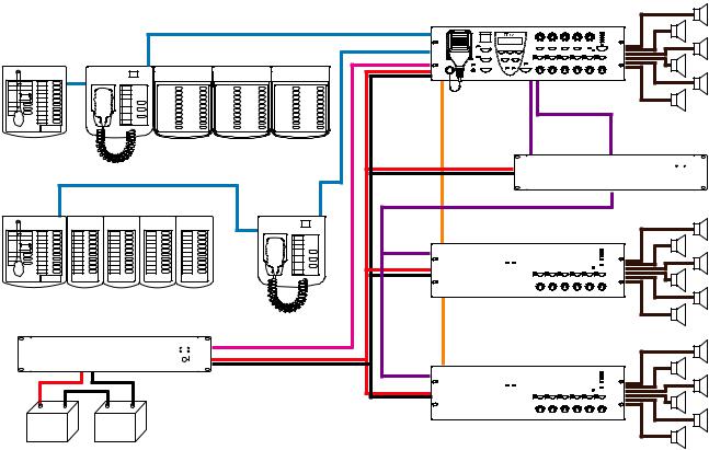
3.2. System Example 2
A standby amplifier is connected to this system, which is ideal for installation in factories and schools.
|
|
|
RM LINK 1 |
VM-3240VA |
|
|
|
|
|
|
|
RM-200M |
RM-300MF |
RM-320F |
RM LINK 2 |
|
|
|
|
|
|||
|
|
|
|
EXT. AMP INPUT |
|
|
|
|
|
VM LINK |
|
|
|
|
|
EXT. PA LINK |
|
|
|
|
|
PA OUT |
VP-2241 |
|
|
|
|
DC POWER |
|
RM-200M |
RM-210 |
RM-300MF |
|
PA OUT |
|
|
|
|
|||
|
|
|
EXT. AMP |
VM-3240E |
|
|
|
|
INPUT |
|
|
|
|
|
|
VM LINK |
|
VX-2000DS |
|
|
|
|
|
|
|
DS LINK |
|
|
|
|
|
|
EXT. AMP |
VM-3240E |
|
|
|
DC POWER |
INPUT |
|
|
|
|
|
|
|
|
Lead-acid Battery
[System outline]
•A 720 W integrated 1-channel emergency/general broadcast system with 18 outputs.
•A VP-2241 standby amplifier is connected to the system. If the Voice Alarm System Amplifier should fail during a general or emergency broadcast, it is automatically switched to the standby amplifier, allowing the broadcast to continue uninterrupted.
•Emergency broadcasts can be made even during power failures if the VX-2000DS Emergency Power Supply is connected. However, general broadcasts are not possible.
8
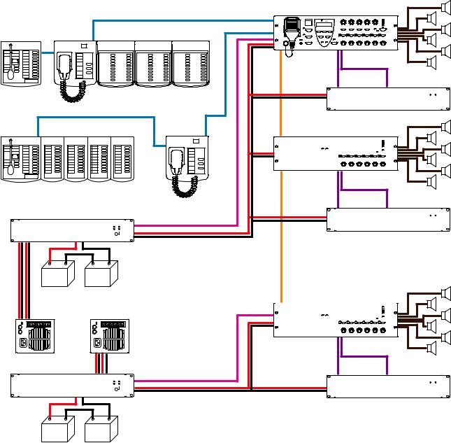
3.3. System Example 3
This example is a system suited to shopping centers.
|
|
VM-3240VA |
|
|
|
|
RM LINK 1 |
|
|
RM-200M |
RM-300MF |
RM LINK 2 |
|
|
RM-320F |
|
|
||
|
|
VM LINK |
EXT. AMP INPUT |
|
|
|
|
|
|
|
|
EXT. PA LINK |
PA OUT |
VP-2241 |
|
|
|
||
|
|
DC POWER |
|
|
RM-200M |
RM-210 |
RM-300MF |
VM-3240E |
|
|
|
VM LINK |
EXT. AMP INPUT |
|
|
|
EXT. PA LINK |
|
|
|
|
|
PA OUT |
VP-2241 |
VX-2000DS |
DC POWER |
|
|
|
|
|
DS LINK |
|
|
|
|
DC POWER |
|
|
Lead-acid Battery |
VM-3240E |
|
|
VX-200PS
EXT. AMP INPUT
VX-2000DS |
EXT. PA LINK |
PA OUT VP-2241 |
|
|
DS LINK |
|
DC POWER |
|
DC POWER |
Lead-acid Battery
[System outline]
•A 1,440 W integrated emergency/general broadcast system with 18 outputs.
•Unlike a 1-channel broadcast system, this system allows paging calls (microphone announcements) to be made over zones other than those currently being used by the BGM broadcast without interrupting the BGM broadcast. Example: It is possible to page over Zone 3 while playing BGM in Zones 1 and 2. BGM broadcasts are made by the VM amplifier and paging calls by the VP amplifier.
•Paging calls can still be initiated even if either the VM amplifier or the VP amplifier should fail.
•Emergency broadcasts can be made even if either the VM amplifier or the VP amplifier should fail.
•Emergency broadcasts can be made even during power failures if the VX-2000DS Emergency Power Supply is connected. However, general broadcasts are not possible.
9
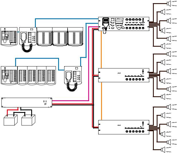
3.4. System Example 4
2-channel broadcast* of emergency announcement broadcast can be made by using the VM-3240VA or VM3360VA Voice Alarm System Amplifier in conjunction with the VM-3240E or VM-3360E Extension Amplifier.
*This function can be used only when all the versions of VM-3000VA firmware, VM-3000E firmware, and VM3000 Setting Software are 3.00 or later.
|
|
|
|
(Example) |
|
|
|
|
Alert |
|
|
|
VM-3360VA |
Alert |
|
|
RM LINK 1 |
|
|
|
|
|
|
|
RM-200M |
RM-300MF |
RM LINK 2 |
|
Alert |
RM-320F |
|
|
||
|
|
|
|
Alert |
|
|
|
VM LINK |
Alert |
|
|
|
|
|
|
|
|
|
Alert |
|
|
|
|
Evacuate |
RM-200M |
RM-210 |
RM-300MF |
|
Evacuate |
|
VM-3360E |
|||
|
|
|
|
|
|
|
|
|
Evacuate |
|
|
|
|
Evacuate |
|
|
|
VM LINK |
|
|
|
|
|
Evacuate |
VX-2000DS |
|
|
|
Evacuate |
|
|
DS LINK |
|
|
|
|
|
|
DC POWER |
Alert |
|
Alert |
|
VM-3360E |
|
Alert |
Lead-acid Battery |
|
|
Alert |
|
Alert |
|
Alert |
[System outline]
•A 1080 W 2-channel emergency broadcast system with 18 outputs.
•Different emergency announcements can be broadcast by each unit. (Example)
Broadcasting Alert announcement from the VM-3360VA and VM-3360E (ID2), and broadcasting Evacuate announcement from the VM-3360E (ID1).
[System requirement]
•Use the VM-3240E or the VM-3360E.
•The same emergency announcement must be saved in the VM-3240VA or VM-3360VA and also in the VM3240E or VM-3360E in advance.
•The settings must be transmitted in advance using the VM-3000 Setting Software version 3.00 or later.
10
3.5. System Example 5
2-channel broadcast* of emergency announcement broadcast can be made by using the VM-3240VA or VM3360VA Voice Alarm System Amplifier and the VM-3240E or VM-3360E Extension Amplifier, each in conjunction with external standby amplifier VP-2241 or VP-2421.
*This function can be used only when all the versions of VM-3000VA firmware, VM-3000E firmware, and VM3000 Setting Software are 3.00 or later.
|
|
|
|
(Example) |
|
|
|
VM-3360VA |
Alert |
|
|
|
RM LINK 1 |
|
RM-200M |
RM-300MF |
RM-320F |
RM LINK 2 |
Evacuate |
|
|
|||
|
|
|
EXT. AMP INPUT |
Alert |
|
|
|
|
|
|
|
|
VM LINK |
Evacuate |
|
|
|
|
|
|
|
|
EXT. PA LINK |
VP-2421 |
|
|
|
PA OUT |
|
|
|
|
DC POWER |
|
RM-200M |
RM-210 |
RM-300MF |
VM-3240E |
Alert |
|
|
|
|
Evacuate |
|
|
|
EXT. AMP INPUT |
|
|
|
|
EXT. PA LINK |
|
|
|
|
PA OUT |
VP-2421 |
VX-2000DS |
DS LINK |
DC POWER |
|
|
|
|
|
|
|
|
|
DC POWER |
|
|
Lead-acid Battery
[System outline]
•A 720 W integrated 2-channel emergency/general broadcast system with 12 outputs.
•Two different emergency announcements, Alert and Evacuate announcements, can be broadcast from one unit.
[System requirement]
•An external amplifier must be connected to each of the VM-3240VA or VM-3360VA, and the VM-3240E or VM-3360E.
•The same emergency announcement must be saved in the VM-3240VA or VM-3360VA and also in the VM3240E or VM-3360E in advance.
•The settings must be transmitted in advance using the VM-3000 Setting Software version 3.00 or later.
•The system must be set to BGM/PAGING mode.
11
4. NOMENCLATURE AND FUNCTIONS
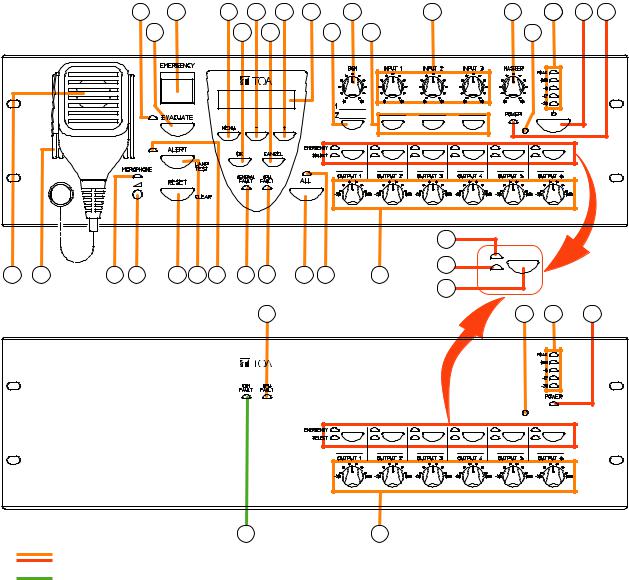
4.1. VM-3240VA and VM-3360VA Voice Alarm System Amplifiers
These amplifiers function as the central units in the VM-3000 system and their power outputs are rated at 240 W for the VM-3240VA and 360 W for the VM-3360VA. Only one unit can be connected in the system. The front panel-mounted LCD displays setting and operation status. The amplifiers also feature an automatic message function and can play back up to 6 recorded general announcements and 2 recorded emergency announcements. Up to 4* RM-300MF Emergency Remote Fireman’s Microphones can be connected, and up to a total of 8* RM-200M general broadcast-use Remote Microphones and RM-300MF Fireman’s Microphones connected.
*These connection numbers are available only when all the versions of VM-3000VA firmware, VM-3000E firmware, and VM-3000 Setting Software are 3.00 or later. When the versions are earlier than 3.00, only up to 2 RM-300 MFs and also up to a total of 4 RM-200Ms and RM-300MFs can be connected. Also, if the system is required to meet the requirements of EN54-16, only one RM-300MF can be connected to each of the VM-3240VA/3360VA's RM1 LINK IN and RM2 LINK IN connector. Besides, up to 2 RM-300MFs in total can be connected.
4.2. VM-3240E and VM-3360E VM Extension Amplifiers
The system can be expanded by connecting up to 9 VM-3240E or VM-3360E Extension Amplifiers. The 240 W VM-3240E and 360 W VM-3360E are both equipped with 6 speaker line outputs. Both also feature 8 inputs and 8 outputs for general broadcasts and 6 inputs and 3 outputs for emergency broadcasts. They are connected to the VM-3240VA or VM-3360VA via the VM Link connector.
[Front] |
|
3 |
|
5 |
|
|
6 |
8 |
10 |
11 |
|
13 |
15 |
16 |
186 |
1 |
2 |
|
|
|
|
|
|
|
|
||||||||||||
VM-3240VA, VM-3360VA |
4 |
|
|
|
7 |
9 |
|
|
12 |
|
14 |
17 |
|
|
|
|||
|
|
|
|
|
|
|
|
|
|
|
|
|
|
|
31 |
|
|
|
19 |
20 |
21 |
22 |
|
23 |
24 |
25 |
26 |
27 |
|
28 |
29 |
|
30 |
32 |
|
|
|
|
|
|
33 |
|
|
|
||||||||||||
|
|
|
|
|
|
|
|
|
|
|
|
|
|
|
|
|
|
|
VM-3240E, VM-3360E |
|
|
|
|
|
|
27 |
|
|
|
|
|
17 |
18 |
|
2 |
||
|
|
|
|
|
|
|
|
|
|
|
|
|
|
|
|
|||
34 30
Common to both Voice Alarm System and Extension amplifiers. |
|
Differing between Voice Alarm System and Extension amplifiers. |
12 |
|
1.Power Switch
Unit is switched between operating and standby modes each time this switch is pressed. Power is always supplied regardless of the switch setting.
2.Live Status Indicator (green) [POWER]
Remains lit while power is supplied.
*As long as the power is connected, this indicator remains lit even if the power is switched OFF.
3.Evacuation Announcement Indicator (red)
Lights whenever an Evacuation announcement is broadcast.
4.Evacuation Announcement Key [EVACUATE]
Can only be used while in emergency broadcast mode.
Pressing this key plays back the recorded Evacuation announcement, which is broadcast from the speaker output(s) selected with the Output Selection key (33). To stop an Evacuation announcement, hold down this key for 3 seconds or more during emergency broadcast.
5.Emergency Activation Switch / Emergency Indicator (red) [EMERGENCY]
Pressing this switch while it is unlit causes it to light while switching output to emergency broadcast mode. (No automatic announcements are made.)
When an emergency broadcast is activated by a control input other than this switch or by the Fireman’s Microphone, the switch flashes and a buzzer sounds, disabling front panel operation.
While flashing, this switch functions as an emergency activation acknowledgement switch. Pressing this switch while it is flashing causes it to stay lit, stopping the buzzer and enabling front panel operation. In any case, this switch goes out once the emergency broadcast is reset.
Steady ON: Lights when the emergency mode is activated either by this switch or by other connected external equipment and subsequently acknowledged, and remains lit until the emergency mode is reset.
Flashing: Flashes when the emergency mode is activated by external equipment other than this switch.
6.Menu Key [MENU]
During emergency broadcasts:
Cannot be used.
During general broadcasts:
Displays the setting item menu.
During settings:
Selects the setting item.
7.OK Key [OK]
During failure indication:
Stops the buzzer when a failure is detected by the surveillance function (functioning as a failure acknowledgment key).*
During setting:
Functions as a confirmation key.
*For more information on surveillance functions, refer to page 51.
8.— (Minus) Key [—]
Decreases setting value numbers.
9.Cancel Key [CANCEL]
Returns the display to the previous screen during settings.
Pressing this switch when a failure occurs reverts the unit back to normal mode. (Refer to "Failure reset operation" on page 57 and "Examples of Failures and Their CounterOperations" on page 59.)
10.+ (Plus) Key [+]
Increases setting value numbers.
11.LCD
Backlit during unit operation.
During emergency or general broadcasts:
Displays operation and failure information.
During settings:
Used to perform settings.
12.BGM Selection Key [BGM]
Displays the BGM (background music) selection screen on the LCD (11). The display switches between the setting screens for Treble, Bass, etc. with each depression of this key. (Refer to "BGM Settings" on page 89.)
13.BGM Volume Control [BGM]
Adjusts the BGM input volume.
14.Input Selection Keys [INPUT 1 – 3]
Display key’s corresponding setting screen on the LCD (11). The display switches between the setting screens for Treble, Bass, etc. with each depression of the selected key. (Refer to "Inputs 1 – 3 Settings" on page 87.)
15.Input Volume Controls [INPUT 1 – 3]
Adjust the input volume for Inputs 1 – 3.
16.Master Volume Control [MASTER]
Sets the output volume for the entire system.
13
17.VM Reset Key
For the VM-3240VA and VM-3360VA:
Resets the entire system.
For the VM-3240E and VM-3360E:
Resets only VM-3240E or VM-3360E Extension amplifiers.
18.Level Meter
Indicates the output level of the unit’s internal amplifier.
19.Emergency Microphone
Only used while in emergency broadcast mode. Press the Talk key located on the side of the microphone to broadcast emergency announcements.
If an emergency attention tone* is enabled, a ding-dong is broadcast when the Press-to-talk switch is pressed. Whether to use the emergency attention tone can be selected on the VM-3000 Setting Software. Refer to "10.2. Emergency Control Input Settings; (2) Emergency attention tone" in the separate VM3000 Setting Software instruction manual.
*This function can be used only when both versions of VM-3000VA firmware and VM-3000 Setting Software are 3.00 or later.
20.Monitor Speaker
Buzzer tone is audible from this speaker when the emergency mode is activated by external equipment other than the unit’s Emergency Activation switch (5) or when any failure occurs.
21.Emergency Microphone Indicator (red)
Lights when the unit’s front panel-mounted emergency microphone (19) is used.
22.Emergency Microphone Volume Control
Rotate clockwise to increase the emergency microphone volume.
Rotate counterclockwise to decrease the emergency microphone volume.
23.Reset Key [RESET]
For emergency broadcasts:
Terminates the emergency broadcast and returns operation to the original general broadcast.
For general broadcasts:
Resets the front panel’s output selection status.
24.Alert Announcement Start Key [ALERT]
For emergency broadcasts:
Plays recorded Alert announcements through the
speaker output selected with the Output Selection key (33). Holding down this key for 3 seconds stops the broadcast.
For general broadcasts:
Used to test LED indicators. (While pressed, LED indicators remain lit and the unit’s internal buzzer sounds.)
25.Alert Announcement Indicator (red)
Remains lit while a recorded Alert announcement is being broadcast.
26.Failure Indicator (yellow) [GENERAL FAULT] (VM-3240VA and VM-3360VA only)
Flashes when a failure occurs while sounding the internal buzzer. Pressing the [OK] key (7) stops the buzzer and switches the indicator from flashing to steady ON. Failure details are displayed on the LCD (11). (When there are multiple failures, they can be checked by moving the screen using the [+] key (10) or [–] key (8)). Failures are not displayed on the LCD when in setting mode. Failures are displayed or notified after exiting the setting mode. Also, if any failure occurs during general or emergency broadcasts, the operation status and failure display are alternately shown on the LCD.
27.CPU Failure Indicator (yellow) [CPU FAULT]
Lights when the CPU fails.
28.All-Zone Call Selection Key [ALL]
Simultaneously selects all speaker outputs for general and emergency broadcasts. Press again to reset the simultaneous selection.
When pressed, all speaker output volume controls do not work in both general and emergency broadcast modes.
29.All-Zone Call Indicator (green) [ALL]
Lights when an all-zone call is initiated.
30.Speaker Output Volume Controls [OUTPUT 1 – 6]
Adjust the output volume of speaker outputs 1 – 6.
31.Emergency Broadcast Output Indicators (red) [EMERGENCY]
Indicate the speaker outputs for emergency broadcasts.
32.Selected Output Indicators (green) [SELECT]
Indicate the speaker outputs selected with the Output Selection key (33).
33.Output Selection Keys
Select corresponding speaker output.
14

Press again to reset the selection.
For general broadcasts:
Select and reset broadcast zones.
For emergency broadcast:
Select and reset speaker outputs for emergency broadcasts made by the unit’s front panelmounted emergency microphone and automatic announcements.
34.Communications Failure Indicator (yellow) [COM FAULT]
(VM-3240E and VM-3360E only)
Flashes when failures are detected in communications with the VM-3240VA or VM3360VA.
[Rear] |
|
|
|
|
|
|
|
|
|
|
VM-3240VA and VM-3360VA |
40 |
41 |
|
43 |
|
|
47 |
|||
|
|
|
|
|
|
|
||||
35 |
36 |
37 |
38 |
39 |
|
42 |
44 |
45 |
46 |
48 |
|
|
49 |
50 |
51 |
52 |
53 |
54 |
55 |
57 |
59 |
60 |
|
|
VM-3240E and VM-3360E |
|
|
|
|
|
56 |
58 |
61 |
|
62 |
|||
|
|
|
|
|
|
|
|
|
|
||||
35 |
36 |
37 |
38 |
|
39 |
|
|
42 |
44 |
45 |
46 |
|
69 |
|
|
49 |
50 |
51 |
52 |
53 |
54 |
55 |
57 |
59 |
60 |
|
|
|
|
|
|
|
|
63 |
|
|
64 |
65 |
66 |
67 |
68 |
Common to both Voice Alarm System and Extension amplifiers.
Differing between Voice Alarm System and Extension amplifiers.
Not used.
35. Speaker Output Terminals 1 – 6 [SP OUT
100 V LINE 1-6, H, C]
Connect speakers to these outputs.
36. External Amplifier Input [EXT. PA AMP
INPUT]
Audio input terminals for VP-2421 or VP-2241
standby amplifier’s PA OUT terminals (100 V line).
37.AC Fuse
Use the following 20 mm type miniature fuses:
4 A (for VM-3240VA and VM-3240E) and 6.3 A (for VM-3360VA and VM-3360E)
15
38.Power Supply Output Terminals [VX-2000DS ONLY, PS OUT]
Supply power to the VX-2000DS Emergency Power Supply. When the VX-2000DS is not connected, use shorting bars to connect PS OUT
(+)to POWER IN (+) and PS OUT (–) to POWER IN (–).
39. 24 V DC Input Terminals [VX-2000DS ONLY, 24 V POWER IN]
Connect power from the VX-2000DS Emergency Power Supply Unit. When the VX-2000DS is not connected, use shorting bars to connect PS OUT
(+) to DC POWER IN (+) and PS OUT (–) to DC POWER IN (–).
40.DIP switch (VM-3240VA and VM-3360VA only)
Used to perform equipment settings.
DIP Switch 1 [LINE/MIC]
Switches input sensitivity of Input 4. (ON: MIC, OFF: LINE; Default: OFF)
DIP Switch 2 [NORMAL/EMERGENCY]
Always set this switch to OFF. (Default: OFF)
DIP Switches 3 – 5
Not used. (Default: OFF)
DIP Switches 6
Set to ON when excluding the front-mounted emergency microphone from the surveillance item. (Default: OFF)
DIP Switch 7 [FIRMWARE]
Set to ON when upgrading firmware version, and OFF to prohibit update. (Default: ON)
DIP Switch 8 [CONFIG]
Set to ON when transferring set data from a PC, and to OFF to prohibit set data transfer. (Default: ON) (For more information on set data transfer, refer to "Transferring Data Edited by PC between the VM-3000VA and a PC" in the separate software manual.)
41.BGM/Paging Recording Output Terminals [REC OUT BGM/PAGING]
(VM-3240VA and VM-3360VA only)
Output BGM and Paging bus audio signals.
42.Status Output Terminals [STATUS OUT]
Provide the following status outputs in synchronization with unit operation:
•Emergency status output
•Failure status output
•CPU OFF status output
43.BGM 1 & 2 Input Terminals [BGM 1, 2] (VM-3240VA and VM-3360VA only)
Connect the BGM sound source. (–10 dB*, 10 kΩ)
*0 dB =1 V
44.Emergency Control Input Terminals 1 – 6 [EMERGENCY CONTROL, IN 1/IN 2]
Connect to an automatic fire alarm system and activate emergency broadcasts, play back/stop automatic emergency announcements and reset emergency broadcasts.
Contact inputs 1 - 5 are no-voltage make contact inputs.
Input 6 is an isolated voltage input which activates when the polarity of the applied voltage (24 V DC is kept applied to this terminal under normal condition) is reversed.
45.DS Link Connector [DS LINK]
Connects to the VX-2000DS Emergency Power Supply’s DS-SF link connector.
46.Not used.
47. Audio Input Terminals 1 – 3 [INPUT 1 – 3] (VM-3240VA and VM-3360VA only)
Electronically-balanced 600 Ω, –10 dB* / –50 dB, XLR/phone jack combination connectors. LINE or MIC input can be selected, and the phantom power supply turned on and off. (Refer to "Inputs 1 – 3 Settings" on page 87.) These inputs can be converted into transformer-balanced terminals using the optional IT-450 transformer. It is also possible to change microphone sensitivity to –30 dB. (Refer to the separate Installation guide.)
*0 dB = 1 V
48.PA Link Connector [PA LINK]
Can be connected to the SX-2000 series when the VP-200VX (Power Amplifier Input Module) is installed inside the VM amplifier.
For the module installation, refer to the separate Installation Guide for VM-3000 Series.
49.AC Input
Connects to an AC outlet using the supplied AC power cord.
50.Attenuator Control Outputs [ATT CTRL]
Connect to external attenuators.
51. Direct Output Terminals [DIRECT OUT 100 V
LINE]
These speaker output terminals (100 V line) provide direct output of paging calls.
52.24 V DC Output [24 V, +, –]
Provide 24 V DC output, max. 0.3 A.
16
53.Functional Ground Terminal
Hum noise may be generated when external equipment is connected to the unit. Connecting this terminal to the functional ground terminal of the external equipment may reduce the hum noise.
Note: This ground is not for protective ground.
54. Control Output Terminals 1 – 8 [CTRL OUT 1
– 8, G]
Control output terminals for general broadcasts. Operations assigned to each contact output are determined by software settings. (For details, refer to "Event Settings" in the separate software manual.)
55. Control Input Terminals 1 – 8 [CTRL IN 1 – 8, G]
Control input terminals for general broadcasts. Functions assigned to each contact input are determined by software settings. (For details, refer to "Event Settings" in the separate software manual.)
56.Audio Input 4 Terminals [INPUT 4] (VM-3240VA and VM-3360VA only)
Electronically-balanced 600 Ω, –10 dB* / –50 dB, screw terminal. Use DIP switch (40) for LINE/MIC switching.
*0 dB = 1 V
57.Remote VOL Terminals 1 & 2 [REMOTE VOL]
Not used.
58.Input 4 Volume Control (VM-3240VA and VM-3360VA only)
Adjusts the audio input terminal 4’s (56) input volume.
59. External Amplifier Link Connector [EXT. PA
LINK]
Connects to the VP-2241 or VP-2421 standby amplifier’s PA Link connector.
60.VM Link Connector [VM Link Out]
Connects to the VM-3240E’s or VM-3360E’s VM Link In connector.
61.LAN Connector [LAN] (VM-3240VA and VM-3360VA only)
Connects to a PC.
62.Remote Microphone Link Connectors 1 & 2 [RM1 LINK IN, RM2 LINK IN]
(VM-3240VA and VM-3360VA only)
Connect the RM-300MF Fireman’s Microphone
or RM-200M Remote Microphone to these connectors.
Note
Only one RM-300MF can be connected to each connector if the system is required to comply with EN54-16.
63.DIP Switch (VM-3240E and VM-3360E only)
Used for unit ID and equipment settings.
DIP Switches 1 & 2 [LOCAL INPUT]
Not used. Default setting: OFF
DIP Switches 3 – 6 [EXTENSION UNIT NO.]
Used for unit ID settings for the VM-3240E and VM-3360E. (Refer to "Connections between VM Amplifiers" on page 133 for ID settings.)
Default settings: ON (Switch 3), OFF (Switches 4
– 6)
DIP Switch 7 [FIRMWARE]
Set this switch to ON to enable firmware version updates, and OFF to prohibit the update.
Default setting: ON
DIP Switch 8 [CONFIG]
Not used.
Default setting: ON
64.Local Input Terminals [LOCAL INPUT] (VM-3240E and VM-3360E only)
Local broadcast can be made when this terminal is used in conjunction with the Control Input terminals (55).
(This function can be used only when all the versions of VM-3000VA firmware, VM-3000E firmware, and VM-3000 Setting Software are 2.00 or later. For details, refer to "6. SYSTEM SETTINGS; 6.8. Local Input Setting" in the separate software instruction manual.).
65.Local Input Volume Control (VM-3240E and VM-3360E only)
Adjusts the input volume of the equipment connected to the Local Input terminal (64).
66.LAN Connector [LAN] (VM-3240E and VM-3360E only)
Not used.
67.VM Link In Connector [VM LINK IN] (VM-3240E and VM-3360E only)
Connect this connector to the VM-3240VA’s or VM-360VA’s VM LINK OUT connector. When using two or more VM-3240Es or VM-3360Es, connect this connector to other VM-3360E’s or VM-3360E’s VM LINK OUT.
17
68. Local Remote Microphone Link Connector |
69. PA Link Connector [PA LINK] |
[LOCAL RM LINK IN] |
Not used. |
(VM-3240E and VM-3360E only) |
|
Not used. |
|
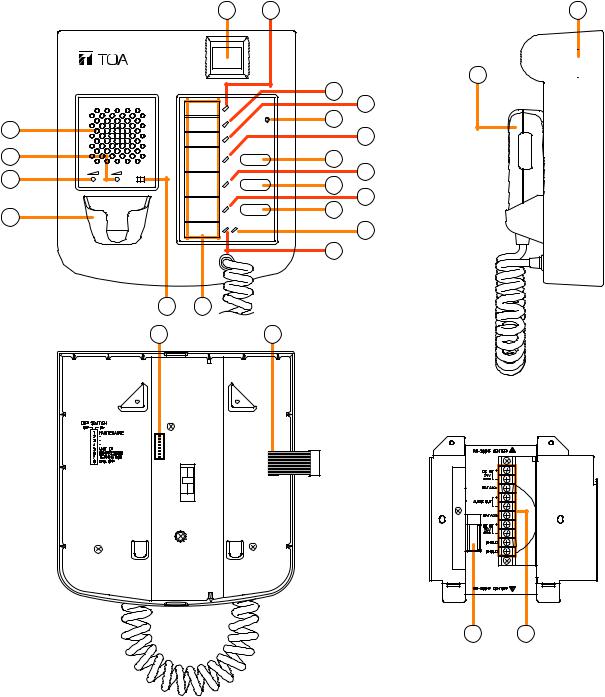
4.3. RM-300MF Fireman’s Microphone
This microphone is designed to be used exclusively for emergency broadcasts made by firemen or other persons when instructing building occupants to evacuate in emergency situations. It can activate the emergency mode, start and stop automatic broadcasts of emergency announcements, reset emergency signals, and make live microphone announcements in emergency situations. Operating the microphone’s CPU OFF switch allows all-zone calls (simultaneous attenuator-free global calls) to go through. No general broadcasts can be made. By connecting the RM-320F Fireman’s Microphone Extension to the RM-300MF Fireman’s Microphone, the zone selection or failure indication/failure acknowledgment/failure reset* function can be enabled. Up to 3 RM-320Fs can be connected to the Fireman’s Microphone, expanding the available keys up to 20 per unit.
*This function can be used only when all the versions of VM-3000VA firmware, VM-3000E firmware, and VM3000 Setting Software are 2.00 or later.
[Top] |
2 |
1 |
[Side] |
|
RM-300MF |
|
|
20
|
9 |
|
|
10 |
|
3 |
11 |
|
12 |
||
|
21 

 EXTENSION
4 |
|
|
|
13 |
14 |
|
MIC |
SP |
CPU |
|
|
||
5 |
|
OFF |
ON |
15 |
|
|
|
|
|
16 |
|
||
|
|
|
|
|
||
6 |
|
|
|
17 |
|
|
|
|
|
|
18 |
|
|
|
|
|
|
|
|
|
|
|
|
|
19 |
|
|
|
|
|
7 |
8 |
|
|
[Bottom] |
|
|
22 |
23 |
|
|
|
|
|
|
|
||
|
|
|
|
|
[Wall mount bracket unit (accessory)] |
|
|
|
|
|
|
24 |
25 |
18
1.Power Indicator (green)
Lights when power is supplied to the unit.
2.Emergency Activation Switch/Emergency Indicator (red)
Places the system in emergency mode while illuminated. Also flashes when the emergency mode is activated by external equipment. In this event, if the switch is pressed to acknowledge the emergency activation, it changes from flashing to steady ON mode.
3.Buzzer
Sounds when a failure is detected or when the emergency mode is activated.
*The buzzer sounds with the same tone in either case.
4.Buzzer Volume Control [SP]
Adjusts the volume of the buzzer (3).
5.Microphone Volume Control [MIC]
Adjusts the volume of the emergency microphone (20).
6.Microphone Holder
Holder for the emergency microphone (20).
7.CPU ON/OFF Switch [CPU]
Turns the CPU on and off. Normally set to the ON position. Turning this switch off allows all-zone calls by the CPU OFF function. To use the CPU OFF function, Switch 8 of the DIP switch (22) on the bottom surface must be set to ON. (Refer to "CPU OFF Function" on page 49 for details.)
8.Indication Label Holder
Write the name, purpose, etc. of the indicator and key on a label and insert the label into the holder from the top. Labels can be printed using the setting software. (For more information, refer to "Printing Remote Microphone Labels" in the separate software manual.)
9.Communication Failure Indicator (yellow/green)
Flashing Yellow
Indicates that a failure has been detected in communications with the VM-3240VA and VM3360VA.
Lit Green
Indicates that the unit is in maintenance mode*. In this event, the unit does not work. To return to normal condition, set Switch 1 of the DIP switch (22) on the bottom surface to OFF.
*Unit is placed in this mode if Switch 1 of DIP switch (22) on the bottom surface is set to ON.
10.CPU OFF Indicator (red)
Lights when the unit is placed in CPU OFF mode using the CPU OFF switch.
11.RM Reset Key
Resets the unit.
12.Evacuation Announcement Indicator (red)
Lights when Evacuation announcements are made.
13.Evacuation Announcement Start Key
Plays the Evacuation announcement when in emergency mode. When the RM-320F Fireman’s Microphone Extension is used, the announcement is broadcast over the zone(s) selected by the RM320F. Pressing this key without first selecting the zones automatically makes an all-zone call. To stop the Evacuation announcement, hold down the key for 3 seconds.
14.Alert Announcement Indicator (red)
Lights when an Alert announcement is made.
15.Alert Announcement Start Key/Lamp Test Key
Plays the Alert announcement when in emergency mode. When the RM-320F Fireman’s Microphone Extension Unit is used, the announcement is broadcast over the zone(s) selected by the RM320F. Pressing this key without first selecting the zones automatically makes an all-zone call. To stop the Alert announcement, hold down this key for 3 seconds. Pressing this key during general broadcast mode allows a lamp test to be conducted.
16.Emergency Reset In-Progress Indicator (red)
Remains lit while the Emergency Reset key (17) is pressed.
17.Emergency Reset Key
Terminates emergency broadcasts to return to general broadcasts.
18.Emergency Microphone In-Use Indicator (green)
Lights when the Emergency Microphone (20) is used for broadcasts.
19.External Emergency Equipment In-Use Indicator (orange/green)
Flashes when external emergency equipment is used for broadcasts.
Orange: Indicates the mode that disables |
|
broadcasts from the unit. |
|
Green: Indicates the mode that allows the unit to |
|
interrupt broadcasts from external equipment. |
19 |
|
20.Emergency Microphone
After the emergency mode is activated, press the Talk key located on the side of the microphone to make an all-zone call or emergency broadcast over the selected zones (the RM-320F is required for zone selection).
If an emergency attention tone* is enabled, a ding-dong is broadcast when the Press-to-talk switch is pressed. Whether to use the emergency attention tone can be selected on the VM-3000 Setting Software. Refer to "10.2. Emergency Control Input Settings; (2) Emergency attention tone" in the separate VM3000 Setting Software instruction manual.
*This function can be used only when both versions of VM-3000VA firmware and VM-3000 Setting Software are 3.00 or later.
21.RM-320F Connector
Connect the RM-320F Fireman’s Microphone Extension Unit to this connector.
22.DIP Switch
Used to set the unit ID number and equipment functions. (Refer to "DIP Switch Functions" on page 91.)
Switch 1 [MAINTENANCE]
Always set this switch to the OFF position. Default setting: OFF
(Refer to "Maintenance Mode" on page 93.)
Note
If this switch is set to ON, the unit is placed in the maintenance mode and the front panel-mounted Communication Failure indicator (9) lights green, causing the unit not to work.
Switches 2, 3
Not used.
Default setting: OFF
Switch 4, 5 [UNIT ID]
Sets the ID number of the Fireman’s Microphone.
Default setting: ON
(Refer to "Unit ID Number Settings" on page 92.)
Switch 6 [COMPRESSION]
Enables/disables compression. Default setting: ON
(Refer to "Compression Settings" on page 92.)
Switch 7 [TERMINATION]
Sets the RM-300MF Fireman’s Microphone that functions as a terminating unit.
Default setting: OFF
(Refer to "Setting the Terminating RM-300MF Unit" on page 93.)
Switch 8 [CPU OFF]
Enables/disables the CPU OFF function. Default setting: ON
(Refer to "CPU OFF Function Enable/Disable Settings" on page 93.)
23.Relay Connector
Connects to the relay connector (24) of the wall mount bracket unit (accessory).
24.Relay Connector
Connect the cable from the RM-300MF Fireman’s Microphone to this connector.
25.Screw Terminal Block
RM Communication Line [DATA (+), DATA (–)]
A control/communication line between the RM300MF Fireman’s Microphone and the VM3240VA or VM-3360VA.
Audio Output Line [AUDIO OUT H/C]
Audio output line from the RM-300MF Fireman’s Microphone to the VM-3240VA or VM-3360VA.
DC Power Supply Input [DC IN 24V +/–]
Power supply line from the VM-3240VA or VM3360VA to the RM-300MF Fireman’s Microphone.
Shield [SHIELD]
Control line used by the VM-3240VA or VM3360VA for confirmation of RM-300MF connections. Ensure that at least one shield is connected.
20
4.4. RM-320F Fireman's Microphone Extension
The RM-320F is an expansion unit for the RM-300MF Fireman’s Microphone. Up to 3 Expansion Units can be added, expanding the available function keys to up to 20 per unit. Zone selection (1 – 20) and failure indication/acknowledgement functions can be assigned to each function key using the dedicated software.
|
3 |
5 |
|
3 |
5 |
|
[Top] |
2 |
4 |
2 |
4 |
[Side] |
6 |
|
|
|
|
|
||
1 |
|
|
|
|
|
|
1.Connection Cable
Used for connection to the RM-300MF or RM320F.
2.Indication Label Holder
Write the name, purpose, etc. of the indicator and key on a label and insert the label into the holder from the top. Labels can be printed using the setting software. (For more information, refer to "Printing Remote Microphone Labels" in the separate software manual.)
3.Emergency Broadcast Zone/Failure Indicators
Indicator function assigned to each indicator is determined by software settings.
Emergency Broadcast Zone Indicators (red)
Light to indicate emergency announcement broadcast zones.
Failure Indicators (yellow)
Flash yellow (before failure acknowledgment) or light yellow (after failure acknowledgment) when a failure is detected.
Failure Reset Indicators* (yellow)
Remain lit while the Failure Reset key is pressed.
4.Broadcast Zone Indicators (green)
Light to indicate the corresponding selected zone.
5.Broadcast Zone Selector / Failure Acknowledgment Keys / Failure Reset Key
Key function assigned to each key is determined by software settings.
Broadcast Zone Selector Keys
Select broadcast zones when in Emergency mode.
Failure Acknowledgment Keys
Keys can be set to acknowledge failures. When an assigned failure occurs, pressing the corresponding key acknowledges the failure.
Failure Reset key*
Key can be set to reset functions. When a failure occurs, remove the cause of the failure, then press the corresponding key, reverting the unit back to normal mode.
6.Expansion Connector
Connect the RM-320F Fireman’s Microphone Extension to this connector.
*This function can be used only when all the versions of VM-3000VA firmware, VM-3000E firmware, and VM-3000 Setting Software are 2.00 or later.
21
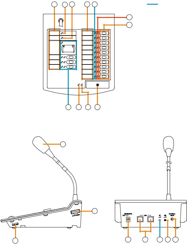
4.5. RM-200M Remote Microphone
The RM-200M Remote Microphone connects to the VM-3360VA or VM-3240VA for the purpose of making general broadcast announcements. It communicates with the VM-3360VA or VM-3240VA through its RS-485 interface. Zone selection or automatic announcement start can be assigned to the function key using the dedicated software. No emergency broadcasts can be made with this microphone.
1 |
2 |
3 |
1 |
4 |
[Top] |
5 |
|
|
|
6 |
10 |
9 |
8 |
7 |
Not used.
11
[Side] |
[Rear] |
13
12 |
14 |
15 |
16 |
17 |
18 |
22
1.Indication Label Holder
Write the name, purpose, etc. of the indicator and key on a label and insert the label into the holder from the top. Labels can be printed using the setting software. (For more information, refer to "Printing Remote Microphone Labels" in the separate software manual.)
2.Power Indicator (green)
Lights when power is supplied to the unit.
3.Communication Failure Indicator (yellow)
Flashes when a failure is detected in communications with the VM-3360VA or VM3240VA.
4.Not used.
Lights when the system is in emergency status.
5.Broadcast Zone / Automatic general broadcast Announcement Start Indicators (green)
Indicator’s function assigned to each indicator is determined by software settings.
Broadcast Zone Indicators
Light when their corresponding zones are selected.
Automatic general broadcast Announcement Start Indicators
Light when an automatic announcement is started.
6.Broadcast Zone Selector / Automatic general broadcast Announcement Start Keys
Key function assigned to each key is determined by software settings.
Broadcast Zone Selector Keys
Select broadcast zones. Pressing the Talk key (7) after zone selection allows microphone announcements to be broadcast over the selected zone(s).
Automatic general broadcast Announcement Start Key
Automatic general broadcast announcements are broadcast over the selected zone(s).
7.Talk Key
This key is used for general broadcast microphone announcements. Pressing the Talk key after zone selection allows microphone announcements to be broadcast over the selected zone(s).
8.Talk Indicator (green)
Lights when the Talk key (7) is pressed.
9.External Microphone In-Use Indicator (orange / green)
Flashes when a paging call is made from the external remote microphone.
Orange: Indicates the mode that disables broadcasts from the unit.
Green: Indicates the mode that allows the unit to interrupt broadcasts from external equipment.
10.Not used.
11.Microphone
Used for making announcements.
12.DIP Switch
Used to set the unit ID number and equipment functions. (Refer to "DIP Switch Functions" on page 91.)
Switches 1 and 2
Set the ID number of the Remote Microphone. Default setting: ON
(Refer to "Unit ID Number Settings" on page 92.)
Switch 3
Not used.
Default setting: ON
Switch 4
Sets the Talk key’s operating system. Default setting: ON
(Refer to "Talk Key Settings" on page 93.)
Switch 5
Not used.
Default setting: ON
Switch 6 [COMPRESSION]
Enables/disables compression. Default setting: ON
(Refer to "Compression Settings" on page 92.)
13.RM-210 Connector [Extension]
Connect the added RM-210 Remote Microphone Extension to this connector.
14.Power Supply Input Connector
The VM-3360VA or VM-3240VA can only supply power to one RM-200M Remote Microphone. Connect the power supply to this connector when using multiple Remote Microphones or Remote Microphone Extensions.
15.Link Connector (RJ45 Connector)
Connects to the VM-3360VA’s, VM-3240VA’s, RM-300MF’s or other RM-200M’s LINK connector.
16.Not used.
17.Microphone Volume Control
Adjusts the volume of the unit’s microphone (11). Rotate clockwise to increase the microphone volume. Rotate counterclockwise to decrease the microphone volume.
18.External Microphone Input Jack (3.5 mm mini jack)
An electret condenser microphone can be connected |
|
to this terminal. Connecting a microphone to this jack |
|
disables the unit’s microphone (11). |
23 |
|
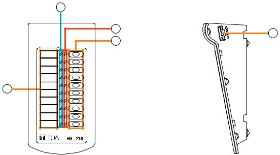
4.6. RM-210 Remote Microphone Extension
The RM-210 is an expansion unit for the RM-200M Remote Microphone. Up to 4 Expansion Units can be added, expanding the available function keys to up to 10 per unit. Zone selection or automatic announcement start functions can be assigned to each function key using the dedicated software. Only the right-side indicators are used.
[Top] |
2 |
|
[Side] |
|
|
3 |
5 |
|
|
4 |
|
|
|
|
|
1 |
|
|
|
1.Indication Label Holder
Write the name, purpose, etc. of the indicator and key on a label and insert the label into the holder from the top. Labels can be printed using the setting software. (For more information, refer to "Printing Remote Microphone Labels" in the separate software manual.)
2.Not used.
3.Broadcast Zone / Automatic Announcement Start Indicators (green)
Indicator’s function assigned to each indicator is determined by software settings.
Broadcast Zone Indicators
Light when their corresponding zones are selected.
Automatic general broadcast Announcement Start Indicators
Light when an automatic announcement is started.
4.Broadcast Zone Selector Keys/ Automatic Announcement Start Keys
Key function assigned to each key is determined by software settings.
Broadcast Zone Selector Keys
Select broadcast zones. Pressing the RM-200M Remote Microphone’s Talk key (7) after zone selection allows microphone announcements to be broadcast over the selected zone(s).
Automatic general broadcast Announcement Start Key
Automatic general broadcast announcements are broadcast over the selected zone(s).
5.Connector [Extension]
Connect the RM-200M Remote Microphone or additional RM-210 Remote Microphone Extension to this connector.
The same terminal is provided on the other side as well.
24
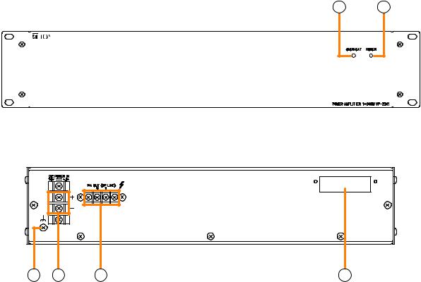
4.7. VP-2241/2421 Power Amplifiers
Two different configurations of power amplifiers can be used in the VM-3000 system: 240 W x 1 channel, and 420 W x 1 channel versions. Mount a VP-200VX Power Amplifier Input module to the module slot on the rear.
2 1
[Front]
[Rear]
3 |
4 |
5 |
1. Channel power indicator [POWER]
Lights green when the power is supplied with the input module mounted.
• Off: VP-200VX not installed
•Lights green: In-use status
•Lights red: Standby status or DC fuse blowout
2.Overheat indicator [OVERHEAT]
If the internals of the power amplifier overheat, this indicator lights yellow and the power amplifier's operation is stopped.
3.Ground terminal
4.DC power inputs [DC POWER IN]
6
5.Output terminals [PA OUT (SP LINE)]
Connect to the power amplifier input terminal of the VM-3240VA/3360VA or VM-3240E/3360E. The speaker line output voltage can be changed with an internal modification.
6.Module slot
Insert the VP-200VX Power Amplifier Input module into this slot.
Connect to the VX-2000DS Emergency Power Supply's DC POWER OUT terminal.
25
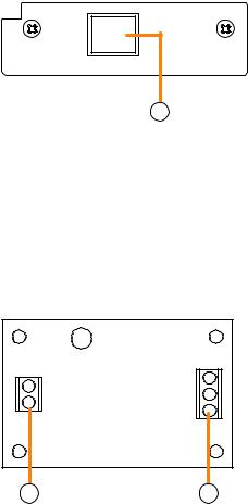
4.8. VP-200VX Power Amplifier Input Module
Insert this module into the Power Amplifier's Input module slot when in use.
[Front]
PA LINK |
VP-200VX |
1
1.Input connector [PA LINK]
This RJ45 connector connects to the VM-3240VA's or VM-3360VA's EXT. PA LINK connector.
Output audio signals are transmitted to the power amplifier, and the power amplifier's audio monitor signals are returned to the module.
It is also possible to retrieve data regarding power amplifier overheating status and blown DC fuses.
4.9. VM-300SV End of Line Unit
Speaker line failure can be detected when an EOL unit is connected between the speaker line end and the emergency input terminal of the VM-3240VA, VM-3360VA, VM-3240E, or VM-3360E.
|
CN2 |
CN1 |
|
H |
|
G |
|
|
|
C |
|
C |
|
|
|
E |
|
|
|
1.Control line connection screw terminal (CN 2)
Connect to the VM-3240VA, VM-3360VA, VM-3240E, or VM-3360E unit's emergency input terminal.
2.Speaker line connection screw terminal (CN 1)
Connect to the speaker line end.
1 |
2 |
26
5. MAKING GENERAL BROADCASTS
5.1. Making Broadcasts from the VM-3240VA or VM-3360VA
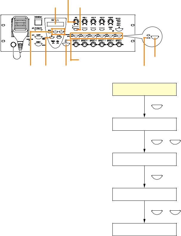
5.1.1. BGM broadcasts
Broadcast musical programs from the BGM sound source connected to BGM input terminals 1 or 2 located on the rear panel of the VM-3360VA or VM-3240VA. Adjust the BGM volume control and the volume control of the designated speakers to an appropriate sound level in advance.
BGM volume control
LCD screen |
BGM selection key |
[VM-3240VA/3360VA]
|
|
All-zone call indicator |
Output selector key |
[–] key |
OK key |
All-zone call key |
Output indicator |
and |
|
|
|
[+] key |
|
|
|
Step 1. Press the BGM selection key. The "Select BGM" screen will be displayed on the LCD.
Step 2. Select either BGM 1 or BGM 2 with the [+] or [–] key.
Step 3. Press the [OK] key to confirm the selected BGM program.
Step 4. Press the all-zone call key or output selector key to select the broadcast zone, then begin the BGM broadcast.
•Pressing the all-zone call key causes the all-zone call indicator to light green, enabling BGM broadcasts over an entire area.
•Pressing an output selector key causes the selected output’s indicator to light green, allowing the BGM program to be broadcast over the corresponding zone.
Step 5. To terminate the BGM broadcast, press either the all-zone call key or output selector key again. The indicator goes out and the BGM broadcast is terminated.
Normal status
1 |
BGM |
|
|
Select BGM screen |
|
S E L E C T |
B G M |
|
2 |
|
B G M 1 |
– |
or |
|
|
+ |
|
Select BGM screen |
|
|
S E L E C T |
B G M |
|
3 |
|
B G M 2 |
OK |
|
|
BGM in-progress |
|
|
screen |
|
|
B G M |
|
|
4 |
|
B G M 2 |
ALL |
or |
|
|
OUTPUT 1 – 6 |
|
BGM in-progress |
|
|
screen |
|
|
B G M
B G M 2
27
5.1.2. Microphone announcements
Make voice broadcasts using the microphone connected to any of audio input terminals 1 – 4 located on the rear panel of the VM-3360VA or VM-3240VA. Perform input sensitivity settings (Line/Mic selection) while viewing the LCD. (Refer to "Inputs 1 – 3 Settings" on page 87.) Also, adjust the volume control for the input the microphone is connected to (Inputs 1 – 4) and the speaker output volume control for the broadcast zone to an appropriate volume in advance.
Note
The microphone on the front panel is intended for emergency broadcasts only. It cannot be used for general broadcasts.
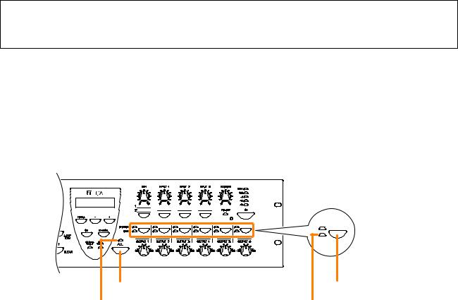
[Front panel-mounted key operation for microphone announcements]
Perform the following setting in advance using the setting software:
Set the priority level of the audio input terminal to which the microphone is connected to "7" (MIX). (Refer to "General Broadcast Priorities" on page 47 for priority levels, and to "Priority Settings" in the separate software manual for how to set priorities.)
Step 1. Press either the all-zone call key or output selector key to select the broadcast zone.
•Pressing the all-zone call key causes the all-zone call indicator to light green, enabling microphone announcement broadcast over an entire area.
•Pressing an output selector key causes the selected output’s indicator to light green, allowing the microphone announcement to be broadcast over the corresponding zone.
[VM-3240VA/3360VA]
All-zone call key |
All-zone call indicator
Output selector key
Output indicator
Step 2. Make a microphone announcement using the microphone connected to the audio input terminal on the rear panel.
Step 3. To terminate the microphone announcement, press the all-zone call key or the same output selector key again.
The corresponding indicator goes out, terminating the microphone announcement.
28
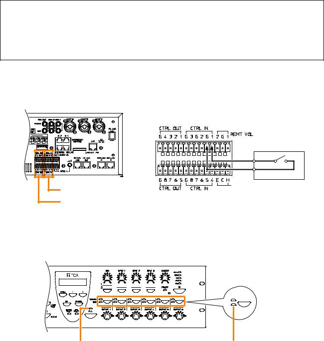
[Making microphone announcements by activating control inputs]
Perform the following settings in advance using the setting software:
•Set the priority level of the audio input terminal to which the microphone is connected to any of "1" – "6". (Refer to "General Broadcast Priorities" on page 47 for priority levels, and to "Priority Settings" in the separate software manual for how to set priorities.)
•Perform settings so that a microphone announcement is broadcast over designated broadcast zones when the control input terminal is activated. (For more information, refer to "General Control Input Settings" in "Event Settings" in the separate software instruction manual.)
Step 1. Close ("Make") the Control Input terminals on the rear panel of the VM-3240VA or VM-3360VA.
[VM-3240VA/3360VA] |
Control Input terminals
Control Output terminals
[Example]
Setting microphone announcement activation for Control Input Terminal 1.
Microphone talk switch
The corresponding all-zone call or output indicator lights green, allowing microphone announcements to be broadcast from the corresponding speaker line.
[VM-3240VA/3360VA]
All-zone call indicator |
Output indicator |
In this event, if interlock outputs have been set, a set contact is provided from the Control Output terminal. (For interlock output settings, refer to "General Control Input Settings" in "Event Settings" in the separate software instruction manual.)
Step 2. Make a microphone announcement using the microphone connected to the audio input terminal on the rear panel.
Step 3. To terminate the microphone announcement, open ("break") the Control Input terminals. The corresponding indicator goes out, terminating the microphone announcement.
29
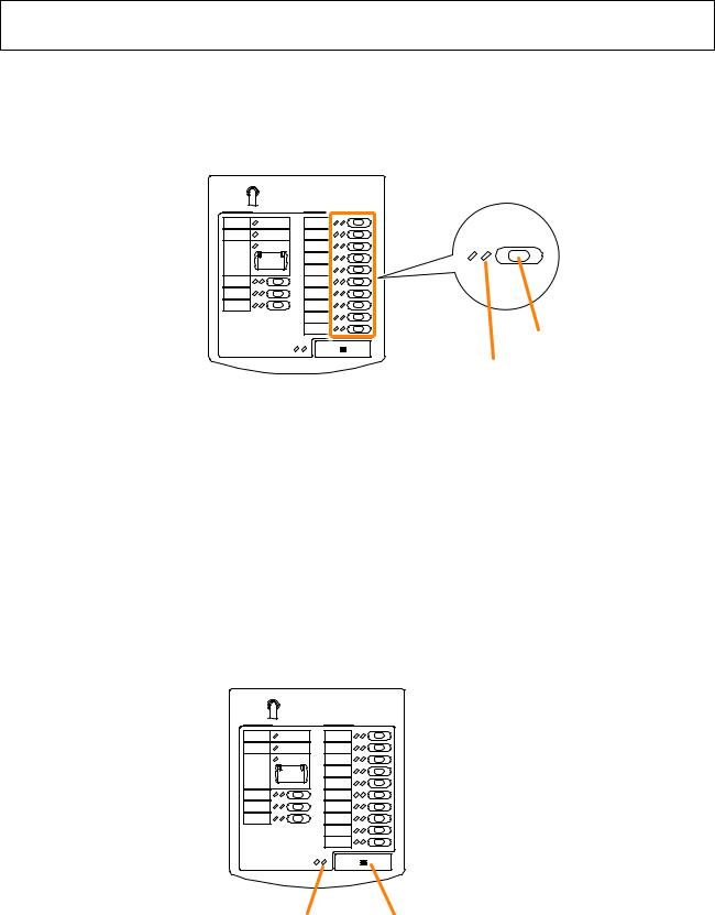
5.2. Broadcasting from the RM-200M
5.2.1. Microphone announcements
Use the RM-200M’s microphone to make announcements.
Perform the following settings in advance using the setting software:
Assign a broadcast zone selection function to the key.
(Refer to "RM Function Key Settings" in "Event Settings" in the separate software instruction manual.)
Step 1. Press the broadcast zone selector key to select the broadcast zone.
The selected zone’s indicator lights green, allowing microphone announcements to be broadcast over the zone assigned to the key.
[RM-200M]
Zone selector key
Zone indicator
Step 2. Press the Talk key to make an announcement.
The talk indicator lights green while the Talk key is pressed.
Notes
Two modes are available for Talk key operation: "PTT" and "Lock" modes.
•When the talk key is set to PTT mode, announcements can only be broadcast while the Talk key is held down. Releasing the Talk key terminates the broadcast and extinguishes the indicator.
•When set to Lock mode, pressing the Talk key initiates a broadcast and pressing the key again terminates the broadcast and extinguishes the indicator.
To set the Talk key mode, use the DIP switch located on the side of the RM-200M. (Refer to "Talk Key Settings" on page 93 for DIP switch settings.)
Talk indicator |
Talk key |
30
 Loading...