


OPERATING INSTRUCTIONS
INFRARED CONFERENCE SYSTEM
TS-800 series
TS-905/-907
DELEGATE |
UNIT |
|
|
TS-802 |
|
|
|
CENTRAL |
UNIT |
|
|
TS- |
|
|
|
|
|
|
800 |
TS-802/-903
CHAI |
|
|
RMAN |
UNIT |
|
|
TS-801 |
|
|
|
TS-800 |
TS-801/-903 |
Thank you for purchasing TOA's Infrared Conference System.
Please carefully follow the instructions in this manual to ensure long, trouble-free use of your equipment.
TABLE OF CONTENTS |
|
|
1. |
SAFETY PRECAUTIONS .............................................................................................. |
4 |
2. |
GENERAL DESCRIPTION ............................................................................................ |
7 |
3. |
FEATURES ........................................................................................................................ |
7 |
4. |
SYSTEM EQUIPMENT CONFIGURATION ............................................................. |
8 |
5. |
NOMENClATURE AND FUNCTIONS |
|
|
5.1. Central Unit TS-800 ........................................................................................................ |
9 |
|
5.2. Chairman Unit TS-801 .................................................................................................. |
12 |
|
5.3. Delegate Unit TS-802 ................................................................................................... |
15 |
6. |
OPERATION |
|
|
6.1. Initiating Speech ............................................................................................................ |
18 |
|
6.2. Initiating Priority Speech (TS-801 only) ......................................................................... |
19 |
7. |
FUNCTION SETTINGS |
|
|
7.1. Setting the Maximum Number of Simultaneous Speakers ............................................ |
20 |
|
7.2. Speech Priority Settings |
|
|
7.2.1. Mode A: first-in/first-out priority (factory-preset switch position) .......................... |
20 |
|
7.2.2. Mode B: last-in/first-out priority ............................................................................ |
20 |
|
7.2.3. Mode C: priority fixed for first-enabled unit, and last-in/first-out priority |
|
|
for all subsequent units ....................................................................................... |
21 |
|
7.3. Mic-Off Function ............................................................................................................ |
21 |
8. |
SYSTEM CONNECTION EXAMPLES .................................................................... |
22 |
9. |
INFRARED SERVICE AREAS |
|
|
9.1. Infrared Transmitter/Receiver ........................................................................................ |
23 |
|
9.2. Chairman Unit and Delegate Unit ................................................................................. |
24 |
10. INSTALLATION AND CONNECTIONS |
|
|
|
10.1. Notes on Installation of the Infrared Transmitter/Receiver Unit .................................. |
25 |
|
10.2. Infrared Transmitter/Receiver Unit Arrangement Examples ....................................... |
26 |
|
10.3. Wiring between the Infrared Transmitter/Receiver Unit and the Central Unit |
|
|
10.3.1. Notes on wiring ............................................................................................... |
27 |
|
10.3.2. Distributor use ................................................................................................. |
27 |
|
10.3.3. Wiring examples .............................................................................................. |
27 |
|
10.4. Mounting the Infrared Transmitter/Receiver Unit |
|
|
10.4.1. Ceiling mounting ............................................................................................. |
29 |
|
10.4.2. Mounting on a microphone stand .................................................................... |
30 |
|
10.5. Connections between the Infrared Transmitter/Receiver Unit and the Central Unit |
|
|
10.5.1. Connecting ...................................................................................................... |
31 |
|
10.5.2. Coaxial cable processing ................................................................................ |
32 |
|
10.6. Using Wired Microphones and Sound Source Equipment |
|
|
10.6.1. Wired microphone use .................................................................................... |
37 |
|
10.6.2. Sound source equipment use ......................................................................... |
37 |
|
10.7. Recording the Conference Contents ........................................................................... |
38 |
2
11. CHAIRMAN AND DELEGATE UNIT INSTALLATION AND SETTINGS ...... 39
12.CHAIRMAN AND DELEGATE UNIT POWER SUPPLY
12.1. BP-900 Lithium-Ion Battery
12.1.1. Inserting the lithium-ion battery ....................................................................... |
40 |
12.1.2. Recharging ...................................................................................................... |
41 |
12.2. AD-0910 AC Adapter .................................................................................................. |
42 |
13. CENTRAL UNIT RACK MOUNTING ....................................................................... |
43 |
14. INSTALLATION STATUS CONFIRMATION .......................................................... |
44 |
15.APPENDIX
15.1. Confirming the Wiring Design
15.1.1. |
Values necessary for calculating the loss ....................................................... |
45 |
15.1.2. |
Values necessary for calculating the voltage drop .......................................... |
45 |
15.2. Computational Equation
15.2.1. |
Finding the wiring loss ..................................................................................... |
46 |
15.2.2. |
Finding the wiring voltage drop ....................................................................... |
46 |
15.3.Design Examples
15.3.1. Example 1: When installing 4 TS-905 Infrared Transmitter/Receiver units
using 4 coaxial cables reaching from the Central unit: ................ |
47 |
15.3.2. Example 2: When installing 4 TS-905 Infrared Transmitter/Receiver units |
|
using 1 coaxial cable reaching from the Central unit |
|
(one 4-branch distributor connected): .......................................... |
48 |
15.3.3. Example 3: When installing each 4 TS-905 Infrared Transmitter/Receiver |
|
units using 4 coaxial cables reaching from the Central unit |
|
(four 4-branch distributors connected): ........................................ |
50 |
15.3.4. Example 4: When installing 16 TS-905 Infrared Transmitter/Receiver Units |
|
using 1 coaxial cable reaching from the Central unit |
|
(five 4-branch distributors connected): ........................................ |
51 |
16. IF A FAILURE IS DETECTED |
|
16.1. Chairman Unit TS-801 and Delegate Unit TS-802 ...................................................... |
53 |
16.2. Central Unit TS-800 .................................................................................................... |
54 |
16.3. Battery Charger BC-900 .............................................................................................. |
54 |
17. SPECIFICATIONS |
|
17.1. Central Unit TS-800 ................................................................................................... |
55 |
17.2. Chairman Unit TS-801, Delegate Unit TS-802 ............................................................ |
56 |
17.3. Microphone TS-903, TS-904 ...................................................................................... |
56 |
17.4. Infrared Transmitter/Receiver TS-905, TS-907 .......................................................... |
57 |
17.5. Lithium-Ion Battery BP-900 ........................................................................................ |
57 |
17.6. Battery Charger BC-900 ............................................................................................. |
58 |
17.7. AC Adapter AD-900 ................................................................................................... |
58 |
17.8. Distributor YW-1022 (2-branch distributor), YW-1024 (4-branch distributor) .............. |
59 |
17.9. Rack Mounting Bracket MB-TS900 ............................................................................ |
59 |
3

1. SAFETY PRECAUTIONS
•Before installation or use, be sure to carefully read all the instructions in this section for correct and safe operation.
•Be sure to follow all the precautionary instructions in this section, which contain important warnings and/or cautions regarding safety.
•After reading, keep this manual handy for future reference.
Safety Symbol and Message Conventions
Safety symbols and messages described below are used in this manual to prevent bodily injury and property damage which could result from mishandling. Before operating your product, read this manual first and understand the safety symbols and messages so you are thoroughly aware of the potential safety hazards.
DANGER |
Indicates an imminently hazardous situation, which, if not avoided, |
will result in death or serious injury. |
Applicable to Lithium-ion battery
•Should the following irregularity be found during use, immediately switch off the power, take the batteries out of the unit, and keep them away from fire. Failure to do so may cause a fire or explosion.
·If you find battery leakage, discoloration, deformation or damage.
·If you detect smoke or a strange smell coming out from the batteries.
•Do not deform, modify, nor solder the batteries. Dosing so may damage the battery's safety or protector mechanism, causing the batteries to fire, leak, or explode.
•Never short the positive and negative terminals with a wire or other metallic objects. Also, avoid carrying or keeping the batteries with metallic objects such as necklaces or hair pins. Doing so may cause the batteries to fire, explode, leak, or heat.
•Never heat the batteries nor throw them into a fire. Doing so may damage the battery's gas relief valve or safety mechanism, causing the batteries to fire or explode.
•Do not dip the batteries into water nor wet the battery terminals. This may corrode the batteries, possibly causing them to fire, explode, leak, or heat.
•Note correct polarity (positive and negative orientation) when inserting the batteries into a battery charger. Doing otherwise may cause them to fire, explode, leak, or heat.
•Do not use, keep, nor leave the batteries near fire or in locations where the temperature rises above 60°C such as in a sun-heated car. Dosing so may damage the battery's safety or protector mechanism, causing the batteries to fire, explode, leak, or heat.
•Be sure to use the BC-900 charger when recharging the batteries. Using other battery charger may cause them to fire, explode, leak, or heat.
•Use the batteries only with the equipment specified. Failure to do so may cause the batteries to fire, explode, leak, or heat.
•Do not drop the batteries nor give them a shock. Doing so may damage the battery's safety or protector mechanism, causing the batteries to fire, explode, leak, or heat.
•There is a fear of loosing one's eyesight if a battery leakage gets in one's eyes. Wash it away with clean water and consult a doctor immediately. If a battery leakage stains one's skin or clothes, wash it away with clean water as there is a fear of impairing the skin.
WARNING |
Indicates a potentially hazardous situation which, if mishandled, could |
result in death or serious personal injury. |
When Installing the Unit
Applicable to Central unit, Chairman unit, Delegate unit, Battery charger, and AC adapter
•Do not expose the unit to rain or an environment where it may be splashed by water or other liquids, as doing so may result in fire or electric shock.
4

•Use the unit only with the voltage specified on the unit. Using a voltage higher than that which is specified may result in fire or electric shock.
•Do not cut, kink, otherwise damage nor modify the power supply cord. In addition, avoid using the power cord in close proximity to heaters, and never place heavy objects -- including the unit itself -- on the power cord, as doing so may result in fire or electric shock.
•Avoid installing or mounting the unit in unstable locations, such as on a rickety table or a slanted surface. Doing so may result in the unit falling down and causing personal injury and/or property damage.
When the Unit is in Use
Applicable to Central unit, Chairman unit, Delegate unit, Battery charger, and AC adapter
•Should the following irregularity be found during use, immediately switch off the power, disconnect the power supply plug from the AC outlet and contact your nearest TOA dealer. Make no further attempt to operate the unit in this condition as this may cause fire or electric shock.
·If you detect smoke or a strange smell coming from the unit.
·If water or any metallic object gets into the unit
·If the unit falls, or the unit case breaks
·If the power supply cord is damaged (exposure of the core, disconnection, etc.)
·If it is malfunctioning (no tone sounds.)
•To prevent a fire or electric shock, never open nor remove the unit case as there are high voltage components inside the unit. Refer all servicing to your nearest TOA dealer.
•Do not place cups, bowls, or other containers of liquid or metallic objects on top of the unit. If they accidentally spill into the unit, this may cause a fire or electric shock.
•Do not insert nor drop metallic objects or flammable materials inside the unit, as this may result in fire or electric shock.
•Do not touch a plug during thunder and lightning, as this may result in electric shock.
Applicable to Battery charger and Lithium-ion battery
•Stop charging if the batteries are not fully charged within 5 hours.
Continuously charging over 5 hours may cause the batteries to fire, explode, leak, or heat.
CAUTION |
Indicates a potentially hazardous situation which, if mishandled, could |
result in moderate or minor personal injury, and/or property damage. |
|
|
|
When Installing the Unit
•These servicing instructions are for use by qualified personnel only.
To reduce the risk of electric shock, do not perform any servicing other than that contained in the operating instructions unless you are qualified to do so. Refer all servicing to qualified service personnel.
Applicable to Central unit
•Be sure to follow the instructions below when rack-mounting the unit. Failure to do so may cause a fire or personal injury.
·Install the equipment rack on a stable, hard floor. Fix it with anchor bolts or take other arrangements to prevent it from falling down.
·To rack-mount the unit, use the supplied rack mounting hardware.
·When connecting the unit's power cord to an AC outlet, use the AC outlet with current capacity allowable to the unit.
5

Applicable to Central unit, Chairman unit, Delegate unit, Battery charger, and AC adapter
•Never plug in nor remove the power supply plug with wet hands, as doing so may cause electric shock.
•When unplugging the power supply cord, be sure to grasp the power supply plug; never pull on the cord itself. Operating the unit with a damaged power supply cord may cause a fire or electric shock.
•When moving the unit, be sure to remove its power supply cord from the wall outlet. Moving the unit with the power cord connected to the outlet may cause damage to the power cord, resulting in fire or electric shock. When removing the power cord, be sure to hold its plug to pull.
•Do not block the ventilation slots on the unit. Doing so may cause heat to build up inside the unit and result in fire.
•Avoid installing the unit in humid or dusty locations, in locations exposed to the direct sunlight, near the heaters, or in locations generating sooty smoke or steam as doing otherwise may result in fire or electric shock.
When the Unit is in Use
Applicable to Central unit, Chairman unit, Delegate unit, Battery charger, and AC adapter
•Do not place heavy objects on the unit as this may cause it to fall or break which may result in personal injury and/or property damage. In addition, the object itself may fall off and cause injury and/or damage.
•If dust accumulates on the power supply plug or in the wall AC outlet, a fire may result. Clean it periodically. In addition, insert the plug in the wall outlet securely.
•Switch off the power, and unplug the power supply plug from the AC outlet for safety purposes when cleaning or leaving the unit unused for 10 days or more. Doing otherwise may cause a fire or electric shock.
Applicable to Central unit, Chairman unit, Delegate unit, and Battery charger
•Use the dedicated AC adapter for the unit. Note that the use of other adapter may cause a fire.
Applicable to Central unit
•Make sure that the volume control is set to minimum position before power is switched on. Loud noise produced at high volume when power is switched on can impair hearing.
Applicable to Chairman unit and Delegate unit
•Make sure that the volume control is set to minimum position before power is switched on. Loud noise produced at high volume when power is switched on can impair hearing.
•When the unit is not in use for 10 days or more, be sure to take the battery out of the unit because battery leakage may cause a fire, personal injury, or contamination of environment.
•Replace the battery only with the TOA BP-900. Using a battery other than designated may cause it to explode. When you discard batteries, please contact the local dealer from whom you bought.
Applicable to Battery charger
•Remove the power supply plug of charger from the AC outlet after charging completion, as doing otherwise may cause a fire.
Applicable to Lithium-ion battery
•When you discard batteries, please contact the local dealer from whom you bought.
Applicable to Central unit, Chairman unit, Delegate unit, and Battery charger
This is a class A product.
In a domestic environment this product may cause radio interference in which case the user may be required to take adequate measures.
6
2. GENERAL DESCRIPTION
The TOA TS-800 Series is a cordless infrared conference system that can be installed and removed quickly and easily. Since the TS-801 Chairman unit and the TS-802 Delegate unit require no wiring, they permit easy installation based on a free layout. The Infrared Transmitter/Receiver unit and recording equipment are connected to the TS-800 Central unit, and the system function settings and status indications are performed at the Central unit.
3. FEATURES
•Since the system is cordless, it can be easily installed and removed, permitting flexible relocation and changes in system layout.
•The system's infrared communication method is not only resistant to radio interference and eavesdropping, but it also permits simultaneous use of systems in adjacent conference rooms with no crosstalk.
•The number of Chairman and Delegate units can be varied as required depending on the number of participants. Up to 64 Chairman and Delegate units can be used per system.
•The maximum number of Infrared Transmitter/Receiver units to be installed in a system is 16 when they are all TS-905 units and 12 when they are all TS-907 units. (Also 12 when both models are mixed.)
•A function to restrict the number of speakers minimizes disorder that could result from simultaneous communications by meeting participants.
•The speech system selection function permits operation when the unit's Talk key is pressed to be set to first- in-first-out, last-in-first-out, or other priority.
•The Mic-Off function automatically turns off the unit's microphone after 30 seconds, even if a user forgets to turn off the microphone after speech completion.
•While the Chairman or Delegate unit is in use, its built-in monitor speaker is turned off, preventing acoustic feedback*.
•The Central unit can be used in conjunction with wired microphones and output source equipment, depending on application.
•Since the Central unit can be connected to recording equipment, it is ideal for use in preparing conference minutes.
•The Chairman unit features a priority speech key which allows it to take precedence over Delegate units when speaking.
•The dedicated microphone used by Chairman and Delegate units employs an XLR connector that not only permits easy attachment and detachment of the microphone, but also saves space when stored.
•Both Chairman and Delegate units can be operated on both their built-in rechargeable lithium-ion batteries or AC power supply.
•Two types of dedicated microphones are made available for the Chairman and Delegate units: "standard" and "long."
* Acoustic feedback: A squeal or howl from the speaker caused by an audio loop condition in which part of the speaker output is picked up by the same microphone, and subsequently amplified and output from the speaker again, quickly building in intensity.
7

4. SYSTEM EQUIPMENT CONFIGURATION
Distributor |
|
YW-1024 (4-branch distributor) |
Infrared transmitter/receiver |
or |
TS-905 or TS-907 |
YW-1022 (2-branch distributor) |
|
|
Note |
|
The maximum number of Infrared Transmitter/Receiver units to be installed |
|
TS-905 only: 16 |
|
TS-907 only: 12 |
|
(Also 12 when both models are mixed.) |
C |
|
|
EN |
|
|
TR |
|
|
AL |
UNIT |
|
|
TS- |
|
|
|
|
|
|
800 |
Infrared transmitter/receiver TS-905 or TS-907
Central unit |
AC adapter |
Power cord |
(supplied with the TS-800) |
(supplied with the TS-800) |
|
TS-800 |
|
|
Microphone (standard) TS-903
or
Microphone (long) TS-904
Chairman unit
TS-801
Delegate unit
TS-802
AC adapter AD-0910 |
Battery charger BC-900 |
|
(for TS-801/802) |
|
(for BP-900) |
|
Lithium-ion battery BP-900 |
Rack mounting bracket MB-TS900 |
|
(for TS-801/802) |
(for TS-800) |
8
5. NOMENCLATURE AND FUNCTIONS
5.1. Central Unit TS-800
[Top]
5 |
6 |
7 |
8 |
2
3
4
1
CENTRAL UNIT TS-800
|
MIC UNIT |
FUNCTION SETTING |
INPUT |
|||
|
|
|
|
|
AUX |
|
Ch1 |
Ch2 Ch3 Ch4 |
|
DATA–EXT–PRIORITY |
|
|
|
|
|
|
|
|
0 |
10 |
DATA |
BATTERY |
MAX MIC UNIT |
PRIORITY |
TIME OUT |
|
|
1 2 4 |
A B C |
OFF ON |
|
|
||
MIC
|
A: FIRST |
|
0 |
10 |
|
POWER |
|
|
|
|
|
B: LATEST |
MIC UNIT INPUT |
HEADPHONES |
|
||
TEST |
C: FIRST: FIXED, NEXT: LATEST |
|
|
|
|
|
|
0 |
10 |
0 |
10 |
9 |
10 |
11 |
12 |
13 |
14 |
15 |
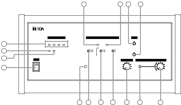
1.Power switch
Setting this switch to the ON position causes the Power indicator to light.
2.Audio signal receiving indicators [Ch1/Ch2/Ch3/Ch4]
Light up when audio signals are received from either Chairman or Delegate units. Audio signals are transmitted or received through 4 channels. The number of channels to be used can be set with the Simultaneous Speaker No. Setting switch (10). These indicators light in the same number as that of the Chairman or Delegate units currently being used for speech. (Which indicator will light is not specified.)
3.Data signal receiving indicator
Lights when control data is received from the Chairman or Delegate unit.
4.Battery indicator
Flashes when the lithium-ion battery of the Chairman or Delegate unit nears complete discharge. (In this event, the Microphone In-Use indicator and the Speech indicator on the corresponding unit also flash.)
Note
Be sure to replace the lithium-ion battery of the corresponding unit immediately if this indicator begins to flash.
5.External control communication indicator
Remains lit during communications with a computer (PC) or operation panel connected to the RS-232C terminal.
6.External control priority indicator
Either lights or flashes when a PC or operation panel connected to the RS-232C terminal performs priority operation. In this event, three function setting switches (10), (11), and (12) cannot be used.
7.AUX input volume control
Adjusts the input signal level of the AUX Input Terminal (17) located on the rear panel.
8.MIC input volume control
Adjusts the input level of the MIC Input Terminal (18) on the rear panel.
9.Installation check button
Installation status for the Infrared Transmitter/Receiver, Chairman unit, and Delegate unit can be checked. (Refer to p. 44.)
9
10.Simultaneous speaker No. setting switch
Used to set the number of Chairman and Delegate units that can be simultaneously operated. The indications [1], [2], and [4] represent the number of simultaneously operable units. (Refer to p. 20.)
Note
This switch is factory-preset to the [1] position.
11.Speech priority selector switch
Determines the priority mode when the Talk key of the Chairman or Delegate unit is pressed. (Refer to p. 20.)
A:First-in-first-out priority
B:Last-in-first-out priority
C:Priority fixed for the first unit, and last-in-first- out priority for all other subsequent units.
Note
This switch is factory-preset to the [A] position.
12.Mic-off setting switch
Automatically turns off Chairman or Delegate unit microphones 30 seconds after speech is completed if the user should neglect to turn off the microphone. (Refer to p. 21.)
Note
This switch is factory-preset to the OFF position.
13.Speech volume control
Adjusts the microphone volume of the Chairman unit and Delegate unit.
14.Headphone jack (Mini-jack)
Connects to a headphone.
15.Headphone volume control
Adjusts the sound volume of the headphone.
10
[Bottom]
|
16 |
17 |
18 |
19 |
20 |
21 |
22 |
DC24V |
3A(MAX) |
AUX |
MIC |
EXT CONTROL |
|
|
CHIME |
|
|
|
|
|
|
REC OUT |
|
|
SHORT |
|
|
|
|
|
|
|
|
INFRARED TRANSMITTER/RECEIVER |
|
|
|
|
|
25 |
24 |
23 |
16.DC input
Connect the supplied AC adapter to this terminal.
17.AUX input terminal
Connect a CD player, tape recorder, or other similar equipment to this terminal.
18.MIC input terminal
Connect a wired microphone to this terminal.
19.External control terminal
Connect this terminal to the serial port of a PC, operation panel, or other external control equipment.
20.Marking plate
Shows the Manufacturer's Name, Model Name, and Electrical Rating.
21.Recording output terminal
Connect an Alternate Recording Deck or MD recorder. An amplifier can also be connected for public address applications.
22.Priority chime volume control
Adjusts the output volume of the chime tone that sounds when the Priority Speech key on the Chairman unit is pressed.
23.Infrared transmitter/receiver unit I/O terminals
Connect the Infrared Transmitter/Receiver unit or distributor to this terminal. By using the YW-1022 (2-branch distributor) and/or YW-1024 (4-branch distributor), the following maximum number of Infrared Transmitter/Receiver units can be connected: 16 units when they are all TS-905 units, 12 units when they are all TS-907 units.
(Also 12 units when both models are mixed.)
24.Short circuit indicator
Lights when the Infrared Transmitter/Receiver unit or its connected cable is shorted.
25.Cable clip
Run the AC adapter cable through this clip to prevent its plug from being removed from the DC input.
To the DC input
Cable clip
AC adapter cable
11
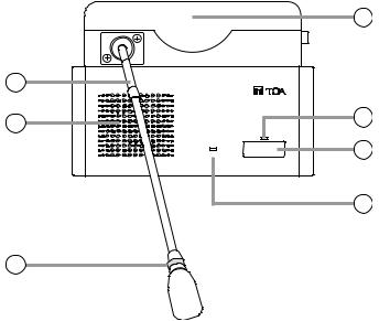
5.2. Chairman Unit TS-801
[Top]
4
2 |
|
CHAIRMAN UNIT TS-801 |
|
1 |
5 |
POWER |
|
PRIORITY |
TALK |
6
7
8
3
Note
No microphone is supplied with the TS-801 Chairman unit.
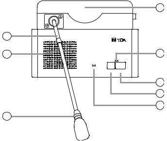
1.Monitor speaker
Speech input from other Chairman or Delegate units and the Central unit is output from this speaker.
Use the right-side Monitor Volume Control (13) to adjust the volume. No sound is output from the speaker of the unit in use while speaking.
2.Microphone
Use either the TS-903 (Standard) or TS-904 (Long) dedicated microphone.
3.Microphone in-use indicator
Lights when the microphone is turned on (for speech) and flashes when the battery level is low.
4.Infrared emitter/detector
The device used to transmit and receive infrared communication signals is built inside this panel.
Note
Never place any object that could block infrared signal access to this part of the unit, as this would prevent the unit from transmitting or receiving its required infrared signal.
5.Speech indicator
Remains lit while the microphone is in use (during speech). The indicator flashes when the unit is out of the communications service area.
6.Talk key
When this key is pressed, both the Microphone InUse indicator (3) and the Speech indicator (5) light, and the microphone turns on. Pressing this key again extinguishes both indicators and turns off the microphone.
7.Priority speech key
Press this key continuously while speaking.
A chime tone sounds when the key is pressed. (The chime can be disabled using the Priority Chime Disable switch (11).)
The microphone turns on and both the Microphone In-Use indicator (3) and the Speech indicator (5) remain lit as long as the key is held down, allowing the voice input from the unit to take precedence over other units. During this interval, other Delegate units cannot be used.
While this key is held down, only the priority speech input is relayed to the Central unit's recording output.
8.Power indicator
Lights when the power is switched ON.
This indicator also flashes when the battery level is low or the unit is outside the communications service area.
12
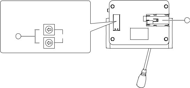
[Bottom]
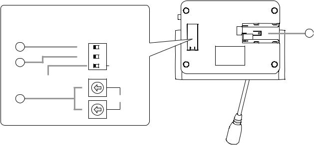
Remove the cover on the bottom side of the unit to expose its setting switches.
Note
The label describing the setting switches is shown
in the following figure.
9
10 |
|
1 |
ON |
PRIORITY |
|
RESET |
RESTORE |
||||
|
|
|
|||
|
|
|
|
CHIME MUTE |
|
11 |
OFF |
3 2 |
|
ON |
|
|
|
NOT USE |
|||
|
Not used. |
|
|
|
|
|
10 |
|
|
|
|
12 |
|
|
|
UNIT ID |
|
|
1 |
|
|
|
9.Lithium-ion battery compartment
Install only a dedicated BP-900 Lithium-Ion Battery in this compartment.
10.Interrupted operation reset switch [5]
Following completion of a priority speech, this switch is used to reset the operating status of Chairman and Delegate units whose operations were interrupted by the depression of a Priority Speech key (7).
Set the switch to RESTORE in order to resume the mode in operation prior to initiation of the priority speech, and to RESET when resumption is not desired.
Note
This switch is factory-preset to the RESET position.
11.Priority chime disable switch [6]
Disables the chime that sounds when the Priority Speech key is pressed.
Set this switch to OFF when sound output is desired, and to ON when no sound is desired.
Note
This switch is factory-preset to the OFF position.
12.Unit address number setting switch
Set the unit address number ([01] – [64]), taking care to ensure that the same number is not duplicated in the system.
If the number [00] is assigned to a unit, the user of that unit cannot speak. However, the unit can be used for monitoring.
Note
This number is factory-preset to [00].
13
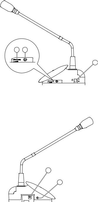
[Right side]
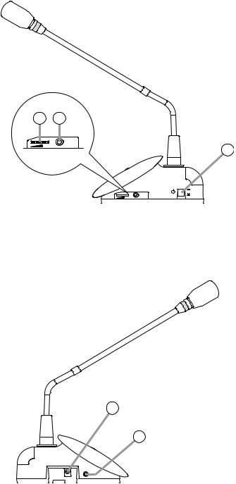
13.Monitor volume control
Adjusts the output volume of the monitor speaker and headphone.
14.Headphone jack
Connect a headphone to this jack (mini-jack). Connecting the headphone cuts off the output from the monitor speaker.
Note
A headphone jack is located on both the left and right side panels.
15.Power switch
Press this switch to switch on the power.
To switch off the power, press this switch again.
[Left side]
16.DC inlet
Connect the dedicated AD-0910 AC Adapter to this terminal.
13 |
14 |
|
HEADPHONES |
15 |
|
|
|
|
|
|
POWER |
|
|
ON |
|
|
OFF |
|
|
HEADPHONES |
16
14
HEADPHONES
Note: No microphone is supplied with the TS-801 Chairman unit.
14
5.3. Delegate Unit TS-802
[Top]
4
2 |
DELEGATE UNIT TS-802 |
|
1 |
|
5 |
|
|
|
|
POWER |
6 |
|
|
|
|
|
TALK |
|
|
7 |
3
Note
No microphone is supplied with the TS-802 Delegate unit.
1.Monitor speaker
Speech input from other Chairman or Delegate units and the Central unit is output from this speaker.
Use the right-side Monitor Volume Control (10) to adjust the volume. No sound is output from the speaker of the unit in use while speaking.
2.Microphone
Use either the TS-903 (Standard) or TS-904 (Long) dedicated microphone.
3.Microphone in-use indicator
Lights when the microphone is turned on (for speech) and flashes when the battery level is low.
4.Infrared emitter/detector
The device used to transmit and receive infrared communication signals is built inside this panel.
Note
Never place any object that could block infrared signal access to this part of the unit, as this would prevent the unit from transmitting or receiving its required infrared signal.
5.Speech indicator
Remains lit while the microphone is in use (during speech). The indicator flashes when the unit is out of the communications service area.
6.Talk key
When this key is pressed, both the Microphone InUse indicator (3) and the Speech indicator (5) light, and the microphone turns on. Pressing this key again extinguishes both indicators and turns off the microphone.
7.Power indicator
Lights when the power is switched ON.
This indicator also flashes when the battery level is low or the unit is outside the communications service area.
15
[Bottom]
Remove the cover on the bottom side of the unit to expose its setting switches.
Note
The label describing the setting switches is shown
in the following figure.
8
|
10 |
9 |
UNIT ID |
|
1 |
8.Lithium-ion battery compartment
Install only a dedicated BP-900 Lithium-Ion Battery in this compartment.
9.Unit address number setting switch
Set the unit address number ([01] – [64]), taking care to ensure that the same number is not duplicated in the system.
If the number [00] is assigned to a unit, the user of that unit cannot speak. However, the unit can be used for monitoring.
Note
This number is factory-preset to [00].
16
[Right side]
10.Monitor volume control
Adjusts the output volume of the monitor speaker and headphone.
11.Headphone jack
Connect a headphone to this jack (mini-jack). Connecting the headphone cuts off the output from the monitor speaker.
Note
A headphone jack is located on both the left and right side panels.
12.Power switch
Press this switch to switch on the power.
To switch off the power, press this switch again.
[Left side]
13.DC inlet
Connect the dedicated AD-0910 AC Adapter to this terminal.
10 11
HEADPHONES |
12 |
|
POWER |
|
ON |
|
OFF |
|
HEADPHONES |
13
11
HEADPHONES
Note: No microphone is supplied with the TS-802 Delegate unit.
17

6. OPERATION
6.1. Initiating Speech
Step 1. Press the Talk key on the Chairman or Delegate unit.
The Speech indicator and Microphone In-Use indicator light, placing the unit in speech mode.
No sound is output from the monitor speaker while both indicators are continuously lit.
Note
The unit cannot be used for speech if the indicators do not light.
CHAIRMAN UNIT TS-801
Speech indicator
POWER
PRIORITY TALK
Microphone in-use indicator
Step 2. Speak into the microphone.
The figure shows the TS-801.
Step 3. Press the Speech key again after speech completion.
The indicators extinguish, and sound can be output from the monitor speaker.
Note
When the user forgets to turn off the microphone, the Mic-Off function automatically turns off the microphone approximately 30 seconds after speech completion. (Refer to p. 21.)
18
 Loading...