


 TJERNLUND PRODUCTS, INC.
1601 Ninth Street • White Bear Lake, MN 55110-6794
PHONE (800) 255-4208 • (651) 426-2993 • FAX (651) 426-9547 Visit our web site • www.tjernlund.com
IMPORTANT!!! UC1 BOARD VERSION X.06 UPDATES
NEW X.06 VERSION UC1 BOARD FEATURES
IMPORTANT: This upgraded circuit board features:
A new #6 power LED
Constant red when 115 VAC is supplied to L & N.
A new color for the #2 LED
Constant blue when fan prover safety circuit is closed.
A revised #5 LED
With no call for heat present, flashes 3 seconds on / 3 seconds off if microcontroller is working properly.
New LED # 6 RED
115V power supplied to UC1 L & N terminals
LED # 2 now BLUE
(previously GREEN)
LED # 5 RED With no call for heat, flashes 3 seconds on / 3 seconds off if microcontroller is working properly.
P1 P2 C GND F
LED 6 (RED) POWER LED (1  9)
9)
LED 1 (AMBER)
LED 2 (BLUE)
LED 3 (GREEN)
LED 4 (RED)
LED 5 (RED)
DRY |
APPLIANCE |
VENTER |
|
|
INTERLOCK |
MOTOR |
|
24 V |
|
RELAY |
RELAY |
|
|
|
|
115 V |
|
|
|
J1 |
J2 |
XL XN |
|
A B 1 |
2 |
3 4 L N |
N M MTR |
IMPORTANT:
For 950-8804 UC1 Replacement Board Kits: If this is a 950-8804 UC1 board kit and you are replacing an existing UC1 board with this new board, note Dip Switch settings on existing UC1 circuit board so that those same settings can be positioned on this replacement circuit board. NOTE: Adhere appropriate included label over existing label in UC1 or SideShot electrical box. Also adhere "Checking Memory for Last Fault Code" sticker on inside of UC1 or SideShot SS1 Series electrical box. On SS2 Series adhere to underside of electrical box.
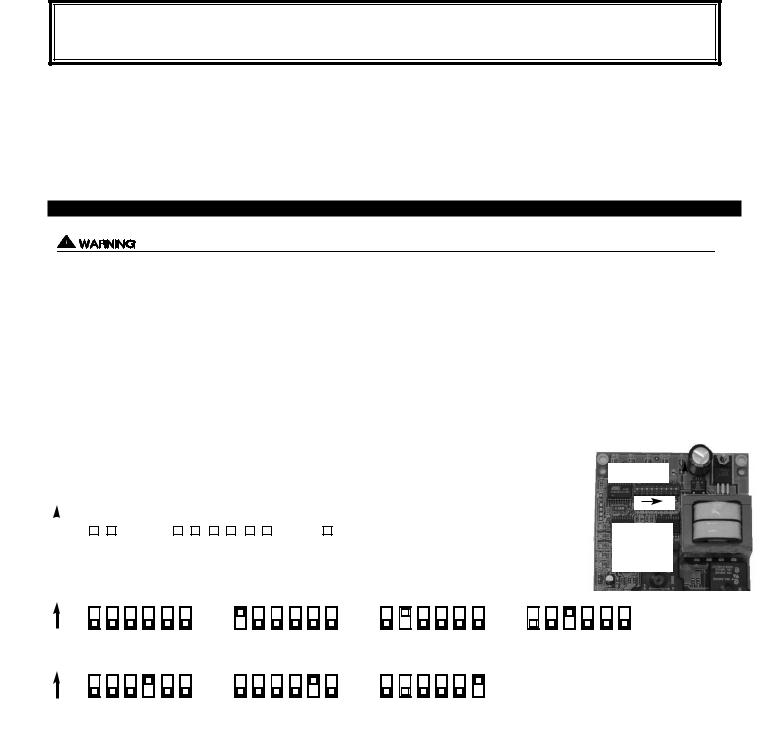
For SideShot Series SS1 Models: The Pre-Cycle Prover Status Check is deactivated from the factory on the SS1 Series. Because of the low set point of the SS1 Fan Prover (as low as .03" w.c.) cross winds may cause the Fan Prover to close prior to a call for heat. Activating the Prover Status Check on the SS1 may cause nuisance lockouts. Important: Deactivate the Pre-Cycle Prover status check if installing this board on a new or existing SS1 installation by pushing the #9 dip switch up or “ON” to disable.
For Draft Inducers with the UC1: Natural draft or winds may be sufficient to close the fan prover switch contacts prior to a call for heat when using the PS1505 fan prover with a draft inducer. Keeping the Pre-Cycle Prover Status Check activated may cause nuisance lockouts. Important: Deactivate the Pre-Cycle Prover status check if installing this board on a new or existing draft inducer installation by pushing the #9 dip switch up or “ON” to disable.
LED INDICATOR LIGHTS
LED #1 (Amber) |
Appliance call for heat. |
|
LED #2 (Blue) |
Safety circuit through P1 & P2 (Venter Fan Prover and/or High Limit). Indicates Venter prover is closed during run cycle. |
|
|
Burner circuit is energized with Interlock Relay contact closure from terminal 3 to 4. |
|
LED #3 (Green) |
Power switched to Venter motor from L to MTR & M. |
|
LED #4 (Red) |
Status / Fault indicator. |
|
LED #5 (Red) |
Used as a status indicator. |
|
LED #6 (Red) |
115 VAC power supplied to board. |
|
P/N: 8505017 |
©2005 TJERNLUND PRODUCTS, INC. ALL RIGHTS RESERVED |
REV. B 07/05 |

LED STATUS INDICATORS |
|
|
LED #4 & #5 (Red) Flashing Alternately |
= |
Venter in Pre-purge. (Pre-Purge options 0, 5, 20, 35 seconds) |
LED #4 & #5 (Red) Flashing in Unison |
= |
Venter in Post-Purge. (Post-Purge options 0, 30 seconds or 1, 2, 4, 8, 16 minutes) |
LED #4 Flashes Continuously* |
= |
Fan Prover opened for more than 10 seconds during burner cycle. |
|
|
(Venter will run for 10 minutes, attempting to make Fan Prover) |
LED #5 (Red) Flashing Intermittently |
= |
With no call for heat, flashes 3 seconds on / 3 seconds off if microcontroller is working properly. |
LED FAULT INDICATORS
Fault conditions are indicated by counting the number of times LED #4 (Red) flashes.
LED #4 Flashes 2 |
Times |
Fan Prover was in electrically closed position prior to venter operation. |
LED #4 Flashes 3 |
Times* |
Fan Prover does not close within 60 seconds after call for heat. |
LED #4 Flashes 4 |
Times* |
Fan Prover did not re-close after 10 minutes of Venter operation. |
LED #4 Flashes 5 |
Times* |
Fan Prover opened for more than 10 seconds during burner cycle but closed within 10 minutes. |
*Investigate cause of Fan Prover short cycling such as; Firing burner at capacities or temperatures exceeding Venter limits, excessive vent pipe runs, elbows directly on venter discharge, high winds, plugged / kinked Fan Prover sensing tube or a faulty Fan Prover switch. In-Forcer model’s intake screen and prefilter, if applicable, should be cleaned if necessary.
IMPORTANT: Fault codes will automatically be displayed after a fault condition occurs. If the call for heat interlock signal or 115 VAC power is removed, the UC1 board will reset and the fault will be stored in memory instead of displayed. Any new fault will replace any previous fault.
CHECKING MEMORY FOR LAST FAULT CODE
IMPORTANT: Prior to accessing the fault code memory, note the settings of the dip switches so that they can be returned to their original Pre / Post-Purge positions. When power is supplied to the UC1 use caution when moving dip switches.
The last fault code can be retrieved at any time by setting all dip switches 1-8 to the up, or “on” position. The last fault code, or lack there of, will be indicated by counting the number of times LED 4 flashes. By moving any of the dip switches back to their original position, the fault code will be cleared. NOTE: The UC1 board must have its 115 VAC power supply present when any of the (1-8) dip switches are moved back to their original position for the fault code to clear.
|
|
|
|
|
|
|
|
|
|
|
|
|
|
|
|
|
REV. D 07/05 |
||
|
|
|
|
|
|
|
|
|
|
|
|
|
|
|
|
|
|||
|
|
|
TJERNLUND PRODUCTS, INC. |
|
|
||||
|
|
|
|
UC1 VERSION |
|||||
|
|
|
1601 Ninth Street • White Bear Lake, MN 55110-6794 |
|
|
|
X.06 |
||
|
|
|
PHONE (800) 255-4208 • (651) 426-2993 • FAX (651) 426-9547 |
|
|
|
|||
|
|
|
Visit our web site • www.tjernlund.com |
|
|
|
|
|
|
|
|
|
|
|
|
|
|
|
|
|
|
|
|
|
|
|
|
|
|
|
|
|
|
|
|
|
|
|
|
|
|
|
|
|
|
|
|
|
|
|
|
|
|
|
|
|
|
|
|
MODEL UC1
INSTALLATION INSTRUCTIONS
!Recognize this symbol as an indication of important Safety Information!
OWNER INSTRUCTIONS, DO NOT DESTROY
THESE INSTRUCTIONS ARE INTENDED AS AN AID TO QUALIFIED, LICENSED
SERVICE PERSONNEL FOR PROPER INSTALLATION, ADJUSTMENT AND
OPERATION OF THIS PRODUCT. READ THESE INSTRUCTIONS THOROUGHLY
BEFORE ATTEMPTING INSTALLATION OR OPERATION. FAILURE TO FOLLOW
THESE INSTRUCTIONS MAY RESULT IN IMPROPER INSTALLATION, ADJUSTMENT, SERVICE OR MAINTENANCE POSSIBLY RESULTING IN FIRE, ELECTRI-
CAL SHOCK, CARBON MONOXIDE POISONING, EXPLOSION, OR PERSONAL INJURY OR PROPERTY DAMAGE.
DO NOT DESTROY. PLEASE READ CAREFULLY AND
KEEP IN A SAFE PLACE FOR FUTURE REFERENCE.
Copyright © 2005, Tjernlund Products, Inc. All rights reserved |
P/N 8504107 |

Tjernlund Products welcomes your comments and questions. Address all correspondence to: Customer Service • Tjernlund Products, Inc. • 1601 Ninth Street • White Bear Lake, MN 55110-6794
Call us toll free at 800-255-4208, visit our web site @ www.tjernlund.com or email us at fanmail@tjfans.com.
TABLE OF CONTENTS |
|
|
Page (s) |
Description and General Information............................................................................................................................... |
1 |
Installation Restrictions and Cautions ........................................................................................................................ |
1, 2 |
UC1 Universal Control Board Features .......................................................................................................................... |
2 |
LED Status / Fault Indicators and Fault Retrieval from Memory ................................................................................. |
2, 3 |
Pre / Post-Purge & Pre-Cycle Prover Status Check Settings...................................................................................... |
3, 4 |
UC1 Installation .............................................................................................................................................................. |
4 |
Electrical Wiring |
|
Specificatons, Warnings, Sequence of Operation & Internal Schematic ..................................................... |
4, 5 |
Venter Ground, Motor and Prover Safety Circuit Connections ........................................................................ |
6 |
Multiple and Milivolt Appliance interlocks ......................................................................................................... |
6 |
Wiring to Gas Fired Appliance ................................................................................................................. |
6, 7, 8 |
Wiring to Oil Fired Equipment .............................................................................................................. |
9, 10, 11 |
UC1 Operation and Draft Check ............................................................................................................................. |
11, 12 |
Troubleshooting Electrical Problems ................................................................................................................. |
12, 13, 14 |
Warranty & Replacement Parts ..................................................................................................................................... |
14 |
DESCRIPTION |
|
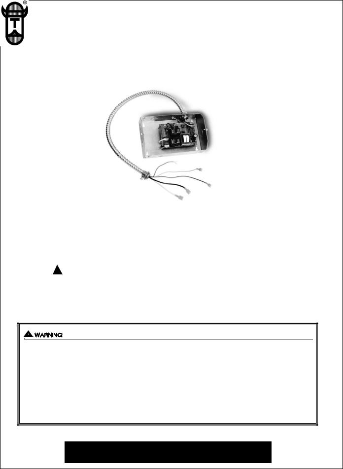
The UC1 is the new standard interlock control for Tjernlund's full line of Power Venters, Draft Inducers and Combustion Air In-Forcers. It can be interlocked with virtually any burner control circuit. Features include: adjustable pre & post purge, LED status / diagnostic indicators, 10 second prover switch delay to avoid burner start up and wind induced short cycling. Interlocks with any 24-115 VAC burner control circuit and also includes “dry” contact actuation option. After each burner cycle the UC1 will continue to operate in post-purge mode to allow the venter to purge the heater and vent of residual flue gases. A factory post-purge time is set at 2 minutes and is adjustable up to 16 minutes, see “Pre / Post Purge and Prover Status Check Dip Switch Settings” on page 3.
GENERAL INFORMATION
Each UC1 is electrically factory line tested before shipment.
After opening carton, inspect thoroughly for hidden damage. If any damage is found notify freight carrier and your distributor immediately and file a concealed damage claim.
Throughout the rest of this installation manual Venter will be synonymous with Power Venter, Draft Inducer or In-Forcer.
INSTALLATION RESTRICTIONS
1.The UC1 Prover Status Check is activated from the factory. When activated the UC1 Universal Control checks across the
P1 & P2 safety circuit Fan Prover to verify that the Fan Prover switch is “Open” upon a call for heat and not stuck “Closed”. See “P1 & P2 Fan Prover Safety Circuit “Open” Upon Appliance Call”, page 4 for details.
2.A Venter post-purge on the UC1 has been factory set at 2 minutes. Confirm that dip switch #5 is in the up or "on" position. Oil fired equipment requires that the post-purge be long enough to eliminate post cycle nozzle drip odor. A longer post-purge may be necessary for longer vent runs or high heat retention, refractory lined combustion chambers. A shorter post-purge may be desired for gas installations. If using the UC1 to control our combustion air In-Forcers a post-purge may not be desired. See “Pre / Post Purge and Prover Status Check Dip Switch Settings”, page 3 for details.
3.The UC1 is intended for indoor installation only. Do not mount the UC1 on a heat source that exceeds 140oF (60oC).
Examples of improper mounting surfaces include vent pipe, top of heater casing or any place where radiant or convective heat would cause the junction box temperature to exceed 140oF (60oC).
CAUTIONS
The UC1 must be installed by a qualified installer (an individual properly licensed and/or trained) in accordance with all local codes or, in their absence, in accordance with the appropriate National Fire Protection Association #31, #54, #211 and the National Electrical Code.
Failure to install, maintain and/or operate the UC1 in accordance with manufacturer's instructions may result in conditions which can produce bodily injury and property damage.
1.The installer must verify that the BTU/hr. input of the appliance does not exceed the recommended input of the any Venter being controlled by the UC1. Refer to the Venter, Inducer or In-Forcer installation instructions for capacities.
2.Disconnect power supply from the UC1 and heating equipment when making wiring connections and servicing the UC1. Failure to do so may result in personal injury and/or equipment damage. LED #6 (RED) should be off with power removed.
1

3.All installation restrictions and instructions in the Venter, Inducer or In-Forcer installation instructions must be adhered to when using the UC1.
4.Make certain power source is adequate for the UC1 and Venter requirements. Do not add equipment to a circuit when the total electrical load is unknown.
UC1 UNIVERSAL CONTROL BOARD FEATURES
P1 - P2 SAFETY CIRCUIT TERMINALS
1 mA @ 5VDC.
SEE WARNING # 1.
DIP SWITCH SETTINGS
Pre-Purge (1-2)
Post-Purge (3-8)
Prover status check (9)
See “Pre / Post Purge &
Prover Status Check Dip
Switch Settings”.
LED STATUS LIGHTS
See “LED Status & Fault
Indicator Section” for details.
APPLIANCE CALL
VOLTAGE SELECTION
IMPORTANT
Place RED voltage jumper in proper location based on appliance call interlock voltage. SEE WARNING # 2. 
C, GND, F AUXILIARY DEVICE
COMMUNICATION TERMINALS
2 mA @ 5VDC. For Tjernlund MAC1E or MAC4E auxiliary devices. SEE WARNING # 1.
P1 P2 C GND F
LED 6 (RED) POWER LED
(1 9)
LED 1 (AMBER)
LED 2 (BLUE)
LED 3 (GREEN)
LED 4 (RED)
LED 5 (RED)
DRY |
APPLIANCE |
VENTER |
|
INTERLOCK |
MOTOR |
24 V |
RELAY |
RELAY |
|
|
J1J2 CALL |
115 V |
|
|
|
JUMPER |
|
|
||
|
|
|
||
Used when the call signal is |
J1 J2 |
XL XN |
|
|
used as the “proven” return |
|
|||
|
|
|
||
signal to the appliance. See |
A B 1 2 3 |
4 L N |
N M MTR |
|
wiring section for details. |
||||
|
|
|
APPLIANCE INTERLOCK TERMINAL BLOCK (A-B, 1-4)
A - B - Dry Contact call. 3 mA @ 5VDC.
SEE WARNING # 1.
1 - 24 or 115 VAC intercepted call. IMPORTANT: RED voltage jumper must match intercepted call voltage.
2 - 24V common or 115V Neutral.
3 - Common terminal to appliance relay contacts. IMPORTANT: J1-J2 jumper routes call voltage at terminal 1 to 3. Remove J1-J2 jumper if a different voltage source is provided to terminal 3.
4 - Normally open terminal of appliance relay. Will be energized from terminal 3 if safety circuit is “proven”.
L / N - 115  VAC POWER SUPPLY BLOCK
115 VAC / 50-60 Hz
Circuit protection provided by installer.
SEE WARNING # 3.
APPLIANCE INTERLOCK RELAY
1 HP MAX LOAD across terminals 3 & 4.
VENTER MOTOR RELAY
1 HP MAX LOAD from terminals L to MTR & M.
XL / XN AUXILIARY DEVICE POWER TERMINALS
115 VAC - Maximum of 0.15 Amps.
Only connect to Tjernlund auxiliary devices.
SEE WARNING # 1.
MTR & M / N LOAD TERMINALS
FROM VENTER MOTOR RELAY
Used to drive Venter Motor.
1 HP MAX LOAD across terminals MTR & M / N.
#1. Power supplied by board. Do not supply power to this area or control damage may result.
#2. Do not supply power to the appliance interlock block with the call selector in the “DRY” position. Control damage may result if power is supplied.
#3. Circuit protection must be provided by the installer. 16 Amps is the maximum current allowed for this device at terminal L.
I |
A 15 Amp circuit breaker is recommended.VETI |
|
|
|
LED STATUS & FAULT INDICATORS |
LED INDICATOR LIGHTS |
||
LED #1 (Amber) |
Appliance call for heat. |
|
LED #2 (Blue) |
Safety circuit through P1 & P2 (Venter Fan Prover and/or Limit). Indicates Venter prover is closed |
|
|
|
during run cycle. Burner circuit is energized with Interlock Relay contact closure from terminal 3 to 4. |
LED #3 (Green) |
Power switched to Venter motor from L to MTR & M. |
|
LED #4 (Red) |
Status / Fault indicator. |
|
LED #5 (Red) |
Used as a status indicator. |
|
LED #6 (Red) |
115 VAC power supplied to board. |
|
2
LED STATUS INDICATORS
LED #4 & #5 (Red) Flashing Alternately = Venter in Pre-purge. (Pre-Purge options 0, 5, 20, 35 seconds)
LED #4 & #5 (Red) Flashing in Unison |
= |
Venter in Post-Purge. (Post-Purge options 0, 30 seconds or 1, 2, 4, 8, 16 minutes) |
LED #4 Flashes Continuously* |
= |
Fan Prover opened for more than 10 seconds during burner cycle. |
|
|
(Venter will run for 10 minutes, attempting to make Fan Prover) |
LLED #5 (Red) Flashing Intermittently |
= |
With no call for heat, flashes 3 seconds on / 3 seconds off if microcontroller is working properly. |
LED FAULT INDICATORS
Fault conditions are indicated by counting the number of times LED #4 (Red) flashes.
LED #4 Flashes 2 |
Times |
Fan Prover was in electrically closed position prior to venter operation. |
LED #4 Flashes 3 |
Times* |
Fan Prover does not close within 60 seconds after call for heat. |
LED #4 Flashes 4 |
Times* |
Fan Prover did not re-close after 10 minutes of Venter operation. |
LED #4 Flashes 5 |
Times* |
Fan Prover opened for more than 10 seconds during burner cycle but closed within 10 minutes. |
*Investigate cause of Fan Prover short cycling such as; Firing burner at capacities or temperatures exceeding Venter limits, excessive vent pipe runs, elbows directly on venter discharge,high winds, plugged / kinked Fan Prover sensing tube or a faulty Fan Prover switch. In-Forcer model’s intake screen and prefilter, if applicable, should be cleaned if necessary.
IMPORTANT: Fault codes will automatically be displayed after a fault condition occurs. If the call for heat interlock signal or 115 VAC power is removed, the UC1 board will reset and the fault will be stored in memory instead of displayed. Any new fault will replace any previous fault.
CHECKING MEMORY FOR LAST FAULT CODE
IMPORTANT: Prior to accessing the fault code memory, note the settings of the dip switches so that they can be returned to their original Pre / Post-Purge positions. When power is supplied to the UC1 use caution when moving dip switches.
The last fault code can be retrieved at any time by setting all dip switches 1-8 to the up, or “on” position. The last fault code, or lack there of, will be indicated by counting the number of times LED 4 flashes. By moving any of the dip switches back to their original position, the fault code will be cleared. NOTE: The UC1 board must have its 115 VAC power supply present when any of the (1-8) dip switches are moved back to their original position for the fault code to clear.
PRE / POST PURGE AND PROVER STATUS CHECK DIP SWITCH SETTINGS
Remove power to UC1 and heating equipment when installing, servicing or changing dip switch settings. Failure to do so may result in personal injury and/or equipment damage. LED #6 (RED) should not be on if 115 VAC supply power is removed from the control.
Pre-purge
Used for longer vent runs to get draft fully established throughout the vent system prior to burner ignition. Also beneficial for negative pressure prone environments. IMPORTANT: Nuisance equipment lockouts may occur if Venter pre-purge is running in conjunction with and is longer than any equipment timing circuit. Pre-purge settings must be shorter than burner control lockout time unless wired prior to burner control timing circuit (i.e. aquastat / thermostat).
Post-purge
A Venter post-purge has been factory set at 2 minutes. Confirm that dip switch #5 is in the up or "on" position. Oil fired equipment requires that the post-purge be long enough to eliminate post cycle nozzle drip odor. A longer post-purge may be necessary for longer vent runs or high heat retention, refractory lined combustion chambers. A shorter post-purge may be desired for gas installations or when using the UC1 to control a combustion air In-Forcer.
|
|
DIP SWITCH NUMBERING |
|
|
|
|
Pre-Cycle |
LED 6 RED |
|
|
|
|||||||||||||
|
|
Pre-Purge |
Post-Purge |
|
|
|
|
Prover Status |
POWER LED |
|
|
|
||||||||||||
|
|
|
|
|
|
ON |
|
|||||||||||||||||
|
|
|
|
|
|
|
|
|||||||||||||||||
|
|
|
|
|
|
Check Activated |
|
|
||||||||||||||||
|
|
|
|
|
|
|
|
|
|
|
|
|
|
|
|
|
|
|
|
|
|
|||
|
|
|
|
|
|
|
|
|
|
|
|
|
|
|
|
|
|
|
|
|
|
|
|
|
|
|
|
|
|
|
|
|
|
|
|
|
|
|
|
|
|
|
|
|
|
|
|
|
|
|
|
|
|
|
|
|
|
|
|
|
|
|
|
|
|
|
|
|
|
|
|
|
|
|
ON |
|
|
|
|
|
|
|
|
|
|
|
|
|
|
|
|
|
|
|
|
|
|
|
|
|
1 |
|
2 |
|
3 |
|
4 |
|
5 |
|
6 |
|
7 |
|
8 |
|
9 |
|
|
|
|
|
||
|
|
|
POST-PURGE SETTINGS (SEE “POST-PURGE” ABOVE PRIOR TO SETTING) |
|
|
|
|
|||||||||||||||||
|
|
|
|
|
|
|
||||||||||||||||||
ON |
3 |
4 |
5 |
6 |
7 |
8 |
3 |
4 |
5 |
6 |
7 |
8 |
3 |
4 |
5 |
6 |
7 |
8 |
3 |
4 |
5 |
6 |
7 |
8 |
0 Seconds |
|
|
30 Seconds |
|
|
1 Minute |
|
|
|
2 Minutes |
|
|
|
|||||||||||
|
|
|
|
|
|
|
|
|
|
|
||||||||||||||
ON |
3 |
4 |
5 |
6 |
7 |
8 |
3 |
4 |
5 |
6 |
7 |
8 |
3 |
4 |
5 |
6 |
7 |
8 |
|
|
|
|
|
|
4 Minutes |
|
|
|
8 Minutes |
|
|
|
16 Minutes |
|
|
|
|
|
|
|
|
||||||||
|
|
|
|
|
|
|
|
|
|
|
|
|
|
|
||||||||||
3
 Loading...