


SS1R
Copyright © 2004, Tjernlund Products, Inc. All rights reserved P/N 8504117
THIS VENT SYSTEM HAS BEEN LISTED FOR USE WITH SPECIFIED
RHEEM, RUUD, WEATHERKING AND HEAT CONTROLLER OIL
FURNACES BY UL AND ULC. SEE FURNACE RATING PLATE FOR
VERIFICATION.
REV. 02/04
OWNER INSTRUCTIONS, DO NOT DESTROY
Recognize this symbol as an indication of important Safety Information!
NOTE: FLUE GAS TEMPERATURES MUST NOT EXCEED
575oF AT VENT SYSTEM INLET.
THESE INSTRUCTIONS ARE INTENDED AS AN AID TO QUALIFIED, LICENSED
SERVICE PERSONNEL FOR PROPER INSTALLATION, ADJUSTMENT AND
OPERATION OF THIS UNIT. READ THESE INSTRUCTIONS THOROUGHLY
BEFORE ATTEMPTING INSTALLATION OR OPERATION. FAILURE TO FOLLOW
THESE INSTRUCTIONS MAY RESULT IN IMPROPER INSTALLATION, ADJUSTMENT, SERVICE OR MAINTENANCE POSSIBLY RESULTING IN FIRE, ELECTRICAL SHOCK, CARBON MONOXIDE POISONING, EXPLOSION, OR PERSONAL
INJURY OR PROPERTY DAMAGE.
!
DO NOT DESTROY. PLEASE READ CAREFULLY AND
KEEP IN A SAFE PLACE FOR FUTURE REFERENCE.
MODEL SS1-R
INSTALLATION INSTRUCTIONS
TJERNLUND PRODUCTS, INC.
1601 Ninth Street • White Bear Lake, MN 55110-6794
PHONE (800) 255-4208 • (651) 426-2993 • FAX (651) 426-9547
Visit our web site • www.tjernlund.com
INCLUDES NEW UC1
UNIVERSAL CONTROL

1
TABLE OF CONTENTS
Page (s)
Description and Specifications ........................................................................................................................................1
Installation Restrictions .................................................................................................................................................2
Cautions .........................................................................................................................................................................2
Safety Inspection of a Previously Used Appliance .....................................................................................................2, 3
SS1-R Terminology ........................................................................................................................................................3
LED Status / Fault Indicators and Fault Retrieval from Memory .....................................................................................3
SS1-R With Integral UC1 Universal Control Board Features .........................................................................................4
Pre / Post-Purge & Pre-Cycle Prover Status Check Settings......................................................................................4, 5
Vent Hood Termination Clearances For U.S. Installations ..........................................................................................5, 6
Vent Hood Termination Clearances For Canadian Installations..................................................................................6, 7
Installation
Tools Required .................................................................................................................................................7
Vent Hood Installation ..................................................................................................................................7, 8
Installation of Rain Shield .................................................................................................................................8
Plenum Installation .....................................................................................................................................9, 10
Installation of Vent Pipe ............................................................................................................................10, 11
Electrical Wiring
Wiring Restrictions ..........................................................................................................................................12
Installation of Oil Solenoid Valve.....................................................................................................................12
Field Wiring Connections & Sequence of Operation...........................................................................12, 13, 14
Selection of Proper Bleed Orifice & Draft Adjustment ............................................................................................14, 15
Combustion Air .............................................................................................................................................................15
System Operation Check Out .......................................................................................................................................15
Troubleshooting Oil Odors.......................................................................................................................................15, 16
Troubleshooting Electrical Problems .................................................................................................................16, 17, 18
Maintenance ..................................................................................................................................................................18
Removal & Replacement of Motor/Wheel ......................................................................................................18
Warranty ........................................................................................................................................................................19
Mounting Templates
Template B Motor Notch ................................................................................................................................20
Template A Vent Hood Terminus....................................................................................................................21
SideShot
®
is a registered trademark of Tjernlund Products, Inc. for their Model SS1-R Vent System.
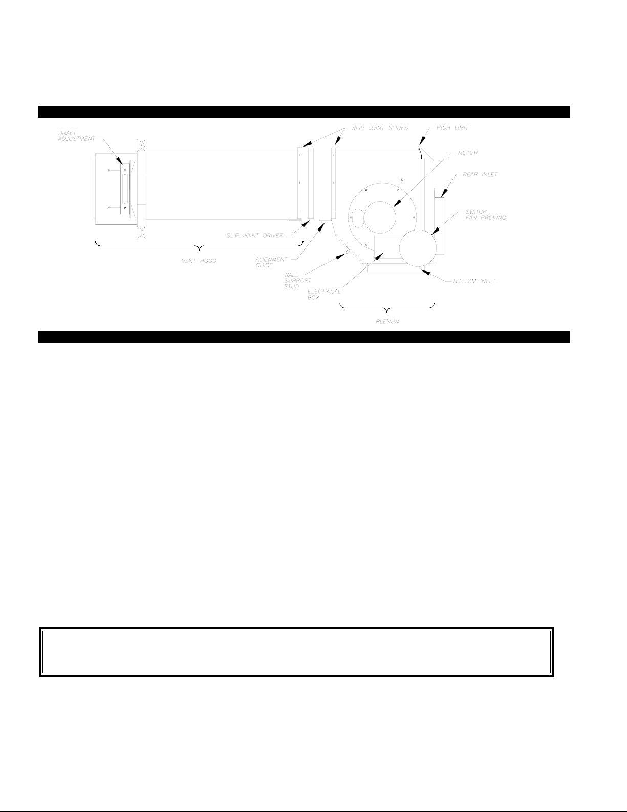
DESCRIPTION
The SS1-R is a mechanical vent system designed and listed for use with specified Rheem, Ruud, Weatherking and Heat Controller oil
fired furnaces. The SS1-R automatically vents the flue gases away from the oil furnace to the outdoors. By combining outside air
with high-tech insulation and maintaining required clearances, surrounding combustible materials remain at safe temperatures. A
factory post-purge time is set at 2 minutes and is adjustable up to 16 minutes, see “Pre / Post-purge Settings” on page 4. The
SS1-R features a safety system consisting of the integral UC1 Universal Control, a Fan Proving Switch and a High Limit temperature control. These devices monitor the SS1-R’s performance and will interrupt the main burner if a venting malfunction is detected.
APPLICATION TABLE
Verify that the total BTU/hr. input of the heating appliance(s) fall
within the proper category listed below. All BTU/hr. capacity ranges
are based on a maximum of 10 linear feet of vent pipe with no more
than 3 - 90
0
elbows. (Two 450elbows are equivalent to one 900elbow)
SPECIFICATIONS
Motor: 115/1/60, 3300 RPM, 212 watts, 2.28 FLA
Fan Proving Switch: Non-adjustable set point of -.04" W.C.
High Limit: Manual reset, N/C contacts, open at 135oF +
10oF.
UC1 Universal Control: See UC1 Universal Control Board Features on page 4.
Pre-Purge: Options (0, 5, 20, 35 seconds); Post-Purge: Factory set at 2 minutes, Options (0, 30 seconds or 1, 2, 4, 8, 16 minutes).
See page 4 for Pre / Post-purge options.
Oil Solenoid Valve: ON - Off control of oil flow to burner; 3-8 second valve opening delay; 120 VAC, .115 Amps, 13.8 VA
12 1/4"16 1/2"27 3/8"
ABC
15 1/8"
8"
D
13 3/4"
EF
7 3/4"G14 3/4"H23 1/4"
I
Rough-In
8” Height
8 3/8” Width
FRONT VIEW
SIDE VIEW

2
GENERAL INFORMATION
These units have been factory tested and rated in accordance with AMCA standard 210, Test Code for Air Moving Devices and
also rated in accordance with the following Canadian Standards: CAN/CSA - B140.0-M87 General Requirements For Oil Burning
Equipment; CAN/CSA - B139-M91 Installation Code For Oil Burning Equipment; CAN3 - B255-M81 Mechanical Flue - Gas Exhausters.
Each SS1-R is electrically factory line tested before shipment. After opening carton, inspect thoroughly for hidden damage. Wheel
should rotate freely. If any damage is found notify freight carrier and your distributor immediately and file a concealed damage claim.
INSTALLATION RESTRICTIONS
1. Do not install on condensing appliances. Use this device only on specified oil fired Rheem, Ruud, Weatherking & Heat
Controller furnaces. Do not use with more than one furnace.
2. A barometric draft control must be used with the SS1-R.
3. Do not use single wall vent pipe in unconditioned or unheated spaces.
4. The SS1-R shall not be installed where flue gas temperatures exceed 575oF at its inlet. Flue gas temperature verification:
Measure temperature of flue gases at the inlet to the SS1-R at time of installation. Measure the temperature after the appliance
and SS1-R operate for at least 15 minutes, allowing flue gas temperature to stabilize.
CAUTIONS
Disconnect power supply from the oil furnace when making wiring connections and servicing the SS1-R. Failure to do so may
result in personal injury and/or equipment damage.
1. The SS1-R must be installed by a qualified installer (an individual properly licensed and/or trained) in accordance with all local
codes. In the absence of local codes, USA installations should be in accordance with the latest editions of the applicable
National Fire Protection Agency (NFPA) code. These are NFPA 31 (Installation of Oil-Burning Equipment), and NFPA 211
(Chimneys, Fireplaces, Vents and Solid Fuel burning Appliances). In addition, USA installations must comply with the National
Electrical Code. In the absence of local codes in Canada, installations must comply with CSA Std 139 (The National Building
Code of Canada) and CSA Std 22.1 (The Canadian Electrical Code).
2. Plan the vent layout so that the code required clearances are maintained from plumbing, wiring and combustible materials.
3. The SS1-R motor shaft must be mounted horizontally to ensure proper operation of the Fan Proving Switch and prevent
motor bearing wear.
4. Flue gas temperatures must not exceed 575oF at SS1-R inlet. Ambient temperature must not exceed 104oF.
5. Make certain the power source is adequate for the SS1-R requirements. Do not add the SS1-R to a circuit where the
total electrical load is unknown.
6. "Safety Inspection of a Previously installed Appliance" must be completed when replacing a conventional chimney
venting system or when SS1-R is installed on Rheem, Ruud, Weatherking or Heat Controller oil fired furnaces.
7. The SS1-R vent system, including vent pipe, must be inspected annually by a qualified individual.
*SAFETY INSPECTION OF A PREVIOUSLY INSTALLED OIL APPLIANCE
(Perform prior to SS1-R installation)
The following procedure is intended as a guide to aid in determining that an appliance is properly installed and is in safe condition
for continuing use.
This procedure is based on central furnace installations and it should be recognized that generalized procedures cannot anticipate
all situations. Accordingly, in some cases deviation from this procedure may be necessary to determine safe operation of the
equipment.
a. Install the SS1-R only on specified Rheem, Ruud, Weatherking & Heat Controller oil fired furnaces.
b. Complete this procedure prior to any attempt at modifications of the appliance or installation of the SS1-R.
c. If there is a condition which could result in unsafe operation, shut off the appliance and advise the owner
of the unsafe condition.
Improper installation, adjustment, alterations, service or maintenance can cause injury, property damage or death. Refer to this
manual. For assistance or additional information consult a qualified installer, service agency or the equipment supplier.
Do not exceed the recommended input range of the SS1-R. Under no circumstances shall the minimum draft adjustment be used
for the larger input range of this product. Improper adjustment may result in the dispersion of flue products (carbon monoxide)
into the building interior causing carbon monoxide poisoning or death.
If oil nozzle is changed or other equipment is added perform “Draft Adjustment Procedure” on page 14 again.
The following steps should be followed in making the safety inspection:
1. Visually inspect the venting system and determine there is no blockage or restriction, leakage, corrosion or other deficiencies
which could cause an unsafe condition.
2. Inspect burner and primary control for proper operation.
3. Inspect heat exchanger for cracks, openings or excessive corrosion. Check both the limit control and fan control for proper
operation.
SS1-R TERMINOLOGY
LED STATUS & FAULT INDICATORS
LED INDICATOR LIGHTS
LED #1 (Amber) Appliance call for heat.
LED #2 (Green) Safety circuit through P1 & P2 (SS1-R Limit & Fan Prover) is verified “Open” upon start-up. Indicates Venter
prover is closed during run cycle. Solenoid valve is energized with contact closure from terminal 3 to 4.
LED #3 (Green) Power switched to SS1-R motor & burner motor from L to MTR & M.
LED #4 (Red) Status / Fault indicator.
LED #5 (Red) 115 VAC power supplied to board. Also used as a status indicator.
LED STATUS INDICATORS
LED #4 & #5 (Red) Flashing Alternately = Venter in Pre-purge. (Pre-Purge options 0, 5, 20, 35 seconds)
LED #4 & #5 (Red) Flashing in Unison = Venter in Post-Purge. (Post-Purge options 0, 30 seconds or 1, 2, 4, 8, 16 minutes)
LED #4 Flashing Continuously* = Fan Prover opened for more than 10 seconds during burner cycle.
(Venter will run for 10 minutes, attempting to make Fan Prover)
LED FAULT INDICATORS
Fault conditions are indicated by counting the number of times LED #4 (Red) flashes.
LED #4 Flashes 2 Times Fan Prover was in electrically closed position prior to venter operation.
LED #4 Flashes 3 Times* Fan Prover does not close within 60 seconds after call for heat.
LED #4 Flashes 4 Times* Fan Prover did not re-close after 10 minutes of Venter operation.
LED #4 Flashes 5 Times* Fan Prover opened for more than 10 seconds during burner cycle but closed within 10 minutes.
* Investigate causes of Fan Prover not making, i.e; Firing burner at capacities or temperatures exceeding Venter limits, excessive
vent pipe runs, high winds, plugged / kinked Fan Prover sensing tube or a faulty Fan Prover. Reset SS1-R High Limit. If Limit
was tripped and SS1-R fires, investigate cause of high heat.
tripped and SS1-R fires, investigate cause of high heat.
CHECKING MEMORY FOR LAST FAULT CODE
IMPORTANT: Prior to accessing the fault code memory, note the settings of the dip switches so that they can be returned to their
original Pre / Post-Purge positions. When power is supplied to the UC1 use caution when moving dip switches.
The last fault code can be retrieved at any time by setting all dip switches 1-8 to the up, or “on” position. The last fault code, or
lack there of, will be indicated by counting the number of times LED #4 flashes. By moving any of the dip switches back to their
original position, the fault code will be cleared. NOTE: The UC1 board must have its 115 VAC power supply present when any of
the (1-8) dip switches are moved back to their original position for the fault code to clear.
IMPORTANT: Fault codes will automatically be displayed after a fault condition occurs. If the call for heat interlock signal
or 115 VAC power is removed, the UC1 board will reset and the fault will be stored in memory instead of displayed. Any
new fault will replace any previous fault.
3
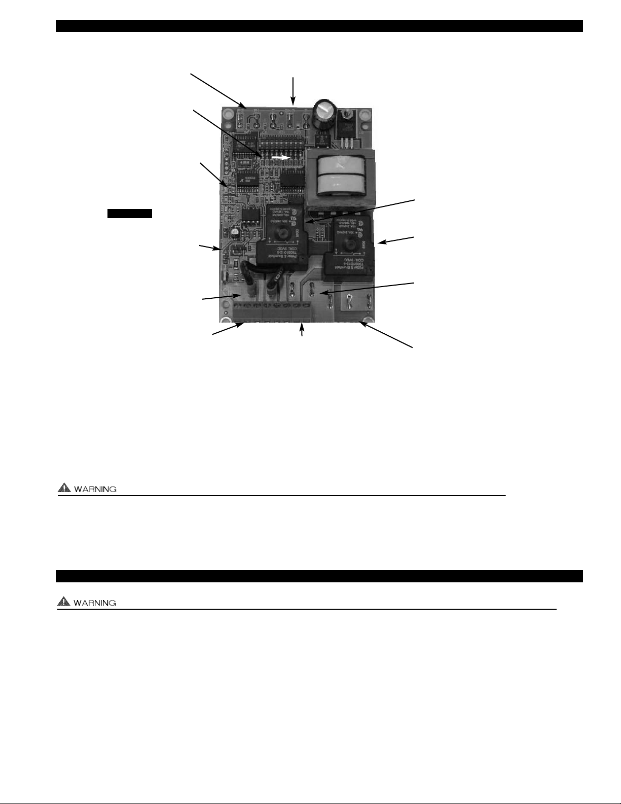
SS1-R WITH INTEGRAL UC1 UNIVERSAL CONTROL BOARD FEATURES
# 1. Power supplied by board. Do not supply power to this area or control damage may result.
# 2. Do not supply power to the appliance interlock block with the call selector in the “DRY” position.
Control damage may result if power is supplied.
# 3. Circuit protection must be provided by the installer. 16 Amps is the maximum current allowed for this device at terminal L.
VETI
A 15 Amp circuit breaker is recommended.
VETI
IA
PRE / POST PURGE AND PROVER STATUS CHECK DIP SWITCH SETTINGS
Remove power to SS1-R and heating equipment when installing, servicing or changing dip switch settings. Failure to do so may result in
personal injury and/or equipment damage. LED #5 (RED) should not be on if 115 VAC supply power is removed from the control.
Pre-purge
Used for longer vent runs to get draft fully established throughout the vent system prior to burner ignition. Also beneficial for negative pressure prone environments. IMPORTANT: Nuisance equipment lockouts may occur if our pre-purge is running in conjunction with and is longer than any equipment timing circuit. Pre-purge settings must be shorter than burner control lockout time
unless wired prior to burner control timing circuit (i.e. aquastat / thermostat).
Post-purge
A Venter post-purge has been factory set at 2 minutes. Confirm that dip switch #5 is in the up or "on" position. Oil fired equipment
requires that the post-purge be long enough to eliminate post cycle nozzle drip odor. A longer post-purge may be necessary for
longer vent runs or high heat retention, refractory lined combustion chambers.
4
LED 1 (AMBER)
LED 2 (GREEN)
LED 3 (GREEN)
LED 4 (RED)
LED 5 (RED)
DRY
24 V
115 V
APPLIANCE
INTERLOCK
RELAY
VENTER
MOTOR
RELAY
A B 1 2 3 4 L N
J1 J2 XL XN
P1 P2 C GND F
(1 9)
N M MTR
XL / XN AUXILIARY DEVICE
POWER TERMINALS
115 VAC - Maximum of 0.15 Amps.
Only connect to Tjernlund auxiliary devices.
SEE WARNING # 1.
LED STATUS LIGHTS
See “LED Status & Fault
Indicator Section” for details.
J1- J2 CALL
JUMPER
Used when the call signal is
used as the “proven” return
signal to the appliance. See
wiring section for details.
APPLIANCE INTERLOCK
TERMINAL BLOCK (A-B, 1-4)
A - B - Dry Contact call. 3 mA @ 5VDC.
SEE WARNING # 1.
1 - 24 or 115 VAC intercepted call.
IMPORTANT: RED voltage jumper must
match intercepted call voltage.
2 - 24V common or 115V Neutral.
3 - Common terminal to appliance relay con-
tacts. IMPORTANT: J1-J2 jumper routes
call voltage at terminal 1 to 3. Remove
J1-J2 jumper if a different voltage source is
provided to terminal 3.
4 - Normally open terminal of appliance relay.
Will be energized from terminal 3 if safety
circuit is “proven”.
L / N - 115 VAC POWER
SUPPLY BLOCK
115 VAC / 50-60 Hz
Circuit protection provided by installer.
SEE WARNING # 3.
MTR & M LOAD TERMINALS
FROM VENTER MOTOR RELAY
Used to drive SS1-R Motor & Burner Motor.
1 HP MAX LOAD across terminals MTR & M / N.
APPLIANCE INTERLOCK
RELAY
1 HP MAX LOAD across
terminals 3 & 4.
VENTER MOTOR RELAY
1 HP MAX LOAD from
terminals L to MTR & M.
P1 - P2 SAFETY CIRCUIT
TERMINALS
1 mA @ 5VDC.
SEE WARNING # 1.
C, GND, F AUXILIARY DEVICE
COMMUNICATION TERMINALS
2 mA @ 5VDC. For Tjernlund MAC1E or
MAC4E auxiliary devices. SEE WARNING # 1.
APPLIANCE CALL
VOLTAGE SELECTION
Place RED voltage jumper in
proper location based on
appliance call interlock voltage. SEE WARNING # 2.
IMPORTANT
DIP SWITCH SETTINGS
Pre-Purge (1-2)
Post-Purge (3-8)
Prover status check (9)
See “Pre / Post Purge &
Prover Status Check Dip
Switch Settings”.

5
PLENUM AND VENT HOOD CLEARANCE FROM COMBUSTIBLES
With an inlet flue gas temperature of 575oF or below, the SS1-R has been Listed for the following clearances from combustible materials:
VENT HOOD TERMINATION CLEAOR
TERMINATION CLEARANCES FOR U.S. INSTALLATIONS
Install the SS1-R according to the requirements of the National Fire Protection Association #31, #54 and #211 as follows,
(See Diagram A):
• The exit terminals of mechanical draft systems shall not be less than 7 feet above grade when located adjacent to public walk
ways.
• A venting system shall terminate at least 3 feet above any forced air inlet located within 10 feet.
• The venting system shall terminate at least 4 feet below, 4 feet horizontally from or 1 foot above any door, window or gravity air
inlet into any building.
• The bottom of the vent terminal shall be located at least 12 inches above grade.
• Arrange the exit terminal so that the flue gases are not directed so as to jeopardize people, overheat combustible structures or
enter buildings.
• Not to be less than 2 feet from an adjacent building.
The SS1-R is also Listed to terminate a minimum of 12" below, above or horizontally from a soffit, deck or adjacent sidewall.
Pre-Purge
Post-Purge
Pre-Cycle
Prover Status
Check Deactivated
DIP SWITCH NUMBERING
1
ON
2
3
4
5
6
7
8 9
ON
PRE-PURGE SETTINGS (SEE “PRE-PURGE”, ON PAGE 4 PRIOR TO SETTING)
12 12 12 12
0 Seconds 5 Seconds 20 Seconds 35 Seconds
ON
POST-PURGE SETTINGS (SEE “POST-PURGE”, ON PAGE 4 PRIOR TO SETTING)
ON
4348657 35678 345678 3 75468
4348657 35678 345678
4 Minutes 8 Minutes 16 Minutes
1 Minute0 Seconds 30 Seconds 2 Minutes
IMPORTANT
Vent Hood and top of Plenum: Zero Clearance
Plenum front and sides: 1/2 inch
Plenum rear: 3 inches
P1 & P2 PRE-CYCLE FAN PROVER STATUS CHECK
The Pre-Cycle Prover Status Check is deactivated from the factory on the SS1-R. Because of the
low set point of the SS1-R Fan Prover (as low as .03" w.c.) cross winds may cause the Fan Prover
to close prior to a call for heat. Activating the Prover Status Check on the SS1-R may cause
nuisance lockouts.
Pre-Cycle
Prover Status
Check Deactivated
9
1 9
LED 1 AMBER
LED 2 GREEN
LED 3 GREEN
LED 4 RED
LED 5 RED
ON
 Loading...