


 TJERNLUND PRODUCTS, INC.
1601 Ninth Street • White Bear Lake, MN 55110-6794
PHONE (800) 255-4208 • (651) 426-2993 • FAX (651) 426-9547 Visit our web site • www.tjernlund.com
CPC-3 CONTROLLED START-UP MANUAL
FOR MODULATING DRAFT & COMBUSTION AIR SYSTEMS
FOR USE WITH AUTO-DRAFT® VSAD-SERIES INDUCERS & VSUB-SERIES BLOWERS
Listings:
The Mechanical Draft System is Listed to UL-378
The Mechanical Combustion Air
System is Listed to UL-1995
THIS INSTALLATION GUIDE IS INTENDED AS AN AID TO QUALIFIED, LICENSED
SERVICE PERSONNEL FOR PROPER INSTALLATION, ADJUSTMENT AND
OPERATION OF THIS UNIT. READ THESE INSTRUCTIONS THOROUGHLY
BEFORE ATTEMPTING INSTALLATION OR OPERATION. FAILURE TO FOLLOW
THESE INSTRUCTIONS MAY RESULT IN IMPROPER INSTALLATION, ADJUST-
MENT, SERVICE OR MAINTENANCE POSSIBLY RESULTING IN FIRE, ELECTRICAL SHOCK, CARBON MONOXIDE POISONING, EXPLOSION, OR PERSONAL INJURY OR PROPERTY DAMAGE.
Copyright © 2004, Tjernlund Products, Inc. All rights reserved. |
P/N 8504125 |

TABLE OF CONTENTS |
PAGE |
Descriptions |
|
Induced Draft / Exhaust .............................................................................................................................................. |
1 |
Combustion Air............................................................................................................................................................ |
1 |
Auxiliary Devices ............................................................................................................................................................ |
2 |
Operation Modes |
|
Automatic .................................................................................................................................................................... |
2 |
Manual......................................................................................................................................................................... |
2 |
Suggested Physical Placement of Components & Maximum Lead Lengths .................................................................. |
3 |
Transducer Sensing Tube Installation ............................................................................................................................. |
3 |
Induced Draft............................................................................................................................................................... |
3 |
“Open” Combustion Air................................................................................................................................................ |
3 |
“Sealed” Combustion Air ............................................................................................................................................. |
3 |
CPC-3 Keypad Layout & Display ................................................................................................................................... |
4 |
CPC-3 Circuit Board Callouts ..................................................................................................................................... |
5, 6 |
Wiring |
|
Low Voltage VFD Control Cable Wiring to CPC-3...................................................................................................... |
6 |
Low Voltage TD-Series Transducer & PSA-1 Manual Mode Fan Prover Wiring to CPC-3 ........................................ |
7 |
Remote Alarm / Auxiliary Device Wiring ..................................................................................................................... |
7 |
VFD to Inducer / C.A. Blower Wiring ...................................................................................................................... |
8, 9 |
CPC-3 Main Power Input & Heater Interlock Wiring................................................................................................. |
10 |
Pre-start up Field Wiring Verification......................................................................................................................... |
10 |
Start Up of CPC-3 |
|
Powering & Initializing CPC-3 ................................................................................................................................... |
10 |
Default CPC-3 Program Settings .............................................................................................................................. |
11 |
Unlocking & Locking the CPC-3 Keypad................................................................................................................... |
11 |
Setting CPC-3 Time and Date................................................................................................................................... |
11 |
Activating the Draft or Combustion Air ...................................................................................................................... |
11 |
Testing the Operation of System components |
|
Test Run Set Up........................................................................................................................................................ |
12 |
VFD and Pressure Transducer Response ................................................................................................................ |
12 |
Checking for Proper Rotation.................................................................................................................................... |
12 |
Draft Adjustment |
|
Draft Set Point Adjustment.................................................................................................................................. |
12, 13 |
Balancing Draft.......................................................................................................................................................... |
13 |
Combustion Air Adjustment |
|
“Open” & “Sealed” Combustion Air Modes of Operation .................................................................................... |
13, 14 |
Combustion Air Set Point Adjustment ....................................................................................................................... |
14 |
“Open” Mode System Start Up.................................................................................................................................. |
14 |
“Sealed” Mode System Start Up ............................................................................................................................... |
14 |
Auxiliary Devices |
|
Alarm Buzzer............................................................................................................................................................. |
15 |
Aux Sensor Set Up ................................................................................................................................................... |
15 |
Aux Device Set Up.................................................................................................................................................... |
15 |
CPC-3 Options |
|
Resetting VFD Drive(s) ............................................................................................................................................. |
15 |
Setting Pressure Units of Measure ........................................................................................................................... |
15 |
Viewing & Resetting Fault History............................................................................................................................. |
16 |
Set Stages & Burner Interlock Verification ................................................................................................................ |
16 |
Setting Pre and Post Purge ...................................................................................................................................... |
16 |
Manual Mode Operation and PSA-1 Fan Prover Switch Adjustment...................................................................... |
16, 17 |
Maintenance & How to Obtain Service Assistance ....................................................................................................... |
17 |
INDUCED DRAFT EXHAUST & COMBUSTION AIR SYSTEMS |
|
INDUCED DRAFT / EXHAUST |
|
The automatic variable speed draft system consists of: |
|
1.A Draft Inducer (either VSAD-Series or VSUB-Series)
2.A CPC-3 Constant Pressure Controller
3.A TD-Series Pressure Transducer
4.A VFD-Series Variable Frequency Drive
5.A PSA-1 Fan Prover for Manual Mode Operation (Included with VSAD & VSUB Series)
COMBUSTION AIR / MAKE-UP AIR
The automatic variable speed combustion air system consists of:
1.A VSUB-Series blower
2.A CPC-3 Constant Pressure Controller
3.A TD-Series Pressure Transducer
4.A VFD-Series Variable Frequency Drive
5.A PSA-1 Fan Prover for Manual Mode Operation (Included with VSAD & VSUB Series)
1
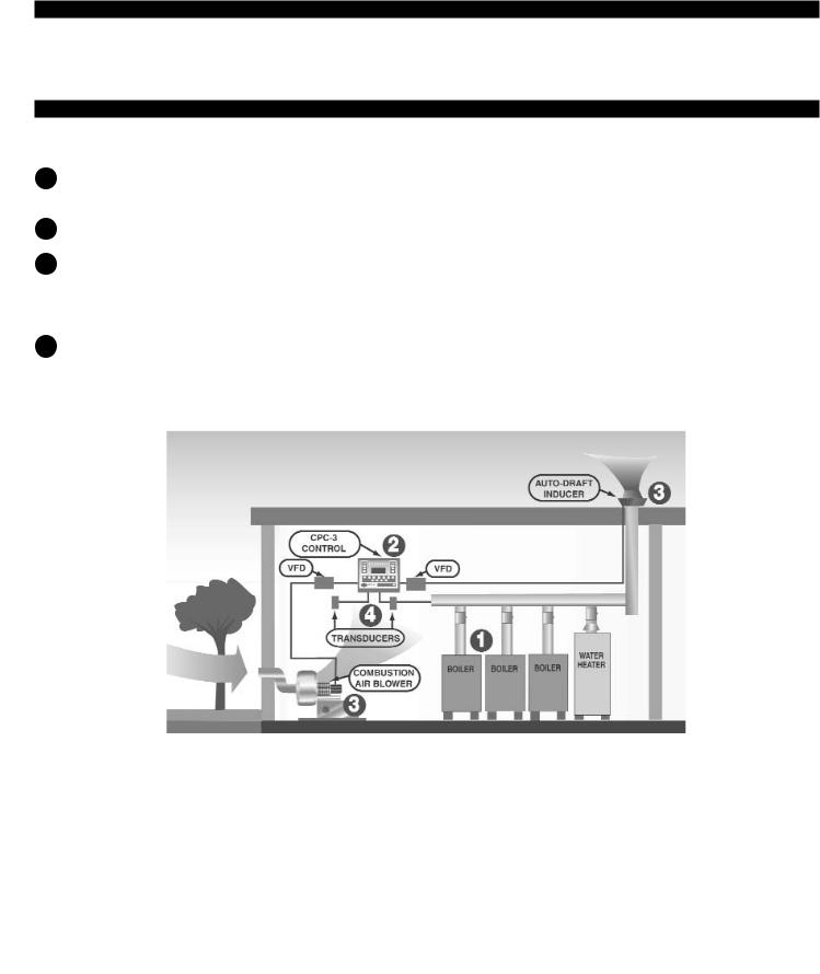
The Patented CPC-3 Controller can simultaneously control both draft and combustion air so only one is needed when both Draft Inducers and Combustion Air Blowers are installed in conjunction with the same heating system. For the remainder of this guide
Inducer will be synonymous to Induced Draft Exhaust and C.A. Blower will be synonymous to Combustion Air Blower.
AUXILIARY DEVICES
The CPC-3 auxiliary devices include an Audible Alarm Buzzer (circuit board mounted), an Auxiliary Device relay for activating a motorized damper in series with the draft and/or combustion function, and a sensor input for a damper end switch. The sensor input can also be configured to accept a signal from a CO detector and lock out all interlocked burners.
CPC-3 AUTOMATIC / MANUAL MODE SEQUENCES OF OPERATION
CPC-3 AUTOMATIC MODE SEQUENCE OF OPERATION, SEE DIAGRAM A
1An aquastat, sequencing control or building management system signals a call for heat. This signal is intercepted and routed through the CPC-3.
The CPC-3 compares actual pressure levels in vent connector and/or mechanical room with previously entered set points.
The Inducer speeds up to achieve the vent pressure set point and/or the combustion air blower simultaneously speeds up to achieve desired pressure set point. These separate functions happen in parallel but are based on software and tolerances unique to the respective draft or combustion air function and to the differential between actual and set point. When the set point is reached the CPC-3 completes the circuit to the heaters allowing ignition sequence to begin.
are constantly monitored by the transducer during the heating cycle. The Inducer / C.A. Blower motor speeds are independently and continuously adjusted to maintain set points entered into the CPC-3. Winds, outdoor temperatures, natural chimney draft, flue gas temperatures, modulating firing rates and building pressure changes will all be compensated for automatically.
DIAGRAM A
heaters will be disrupted for 1 minute if at any time the draft cannot be maintained within the times and tolerances of the software. After this restart delay the CPC-3 will once again try to reach the system set points. If successful, the system will sequence normally. If not successful, the CPC-3 will lock out the heaters until it is manually reset. Up to 5 fault codes will be stored memory.
CPC-3 MANUAL MODE SEQUENCE OF OPERATION
Manual Mode is a method of setting Draft and/or Combustion Air at a fixed speed. It was developed to be used in emergency cases where a transducer is not operational. In Manual mode, the heaters are allowed to operate as long as the manual mode PSA-1 Fan Prover Switch is closed. WARNING: Because Manual Mode is a method of setting a fixed speed for Draft and/or Combustion Air, consideration must be given to over-drafting and/or excessive combustion air supply, See “Manual Mode Operation and PSA-1 Fan Prover Switch Adjustment”, page 16. Deactivate heaters not necessary in an emergency situation to reduce the chance for these conditions. To shut off heater calls from being processed, refer to the “SET STAGES” option, page 16 or shut off the service switch to each heater.
2
SUGGESTED COMPONENT PHYSICAL PLACEMENT
Although it is not necessary to install the CPC-3 and related VFD(s) adjacent to each other it is highly recommended since both displays may need to be viewed simultaneously during system startup or servicing. A faulted VFD can be reset from either the CPC-3 or the VFD.
MAXIMUM LEAD LENGTH FROM CPC-3 CONTROLLER: Transducer: 150 feet with 18 AWG (3 leads required)
Manual Mode PSA-1 Proving Switch: 325 feet with 18 AWG (2 leads required) VFD Control Signal: 220 feet with 18 AWG (10 leads required)*
*VFD comes with 10 foot set of leads terminated with a VFD quick connect
MAXIMUM LEAD LENGTH FROM VFD TO INDUCER/BLOWER: 230 VAC Models: 300 feet with 14 AWG, 600 VAC Insulation
460 VAC Models: 100 feet with 14 AWG, 600 VAC insulation
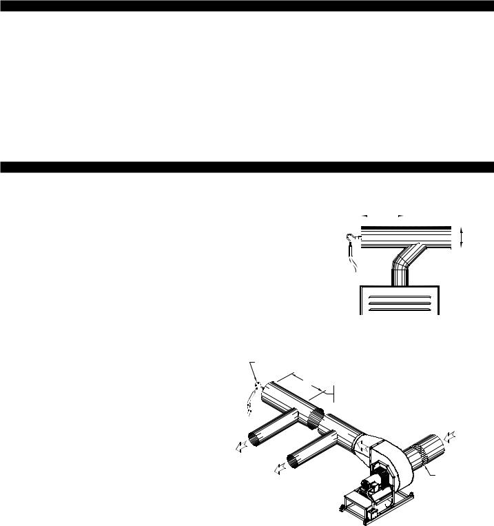
TRANSDUCER SENSING TUBE INSTALLATION
FOR MECHANICAL DRAFT INSTALLATIONS |
DIAGRAM B |
|
|
The TD-2 Transducer sensing tube should be installed in |
|
the cap of a tee or rear of a common manifold. The tee is |
|
necessary so that only static pressure is measured. If the |
|
transducer sensing tube is installed in the side of a vent |
|
pipe it will also measure velocity pressure, giving an incor- |
|
rect signal back to the CPC-3 Controller. If mounting on the |
|
side of the pipe is unavoidable, the sensing tube should be |
|
flush to the interior wall of the vent pipe. Typically, draft |
|
applications should sample at a point in back of the vent |
|
connection that is farthest from the inducer/blower, See |
|
Diagram B. |
|
IF POSSIBLE, THE SENSING TUBE SHOULD BE 2 TIMES THE DIAMETER OF THE PIPE BACK FROM THE MANIFOLD.
|
|
|
|
|
2D |
|
|
|
|
|
|
|
|
D |
|
|
|
|
|
|
|
|
|||||||
|
|
|
|
|
|
|
|
|
|
|
|
|
|
|
|
|
|
|
|
|
|
|
|
|
|
|
|
|
|
|
|
|
|
|
|
|
|
|
|
|
|
|
|
|
|
|
|
|
|
|
|
|
|
|
|
|
|
|
|
|
|
|
|
|
|
|
|
|
|
|
|
|
|
|
8054004 12/8/04
HEATER FURTHEST
FROM VENTER
FOR “SEALED” COMBUSTION AIR APPLICATIONS
The TD-2 Transducer sensing tube should be installed in the capped end of a common supply manifold. This is necessary so that only static pressure is measured. If the transducer sensing tube is installed in the side of a duct it will also measure velocity pressure, giving an incorrect signal back to the CPC-3 Controller. If mounting on the side of the duct pipe is unavoidable, the sensing tube should be flush to the interior wall of the duct. If a filter is installed it must be positioned between the blower inlet and intake opening, See Diagram C.
DIAGRAM C
SENSING TUBE |
|
|
2D |
COMBUSTION |
IF POSSIBLE, THE SENSING TUBE SHOULD |
BE 2 TIMES THE DIAMETER OF THE PIPE |
|
|
BACK FROM THE LAST HEATER MANIFOLD. |
|
AIR |
LAST |
HEATER |
|
MANIFOLD |
|
|
||
|
|
|
|
|
|
FIRST |
HEATER |
|
|
|
COMBUSTION
AIR INTAKE
INSTALLER-SUPPLIED FILTRATION MUST BE ON BLOWER INLET SIDE.
FIGURE 8054005 12/9/04
FOR “OPEN” COMBUSTION AIR APPLICATIONS
In "Open" mode the mechanical room air is sampled and an adjacent space is referenced. Referencing an adjacent space within the building typically provides a more stable reference pressure than referencing outdoor air. In both cases, the goal is to reference static pressure. Don't sample pressures at locations that can be affected by frequently opened doors, elevator shafts, ventilation fans and diffusers. The model IPS-1 includes a decorative cover, sampling tube and fittings and when used in conjunction with the TD-3 Transducer may be used to sample indoor reference pressure. It reduces the effects of air movement on the sampling tube and provides a finished look. Varying wind speeds will affect outdoor reference pressure and are difficult to neutralize. If sampling outdoor reference pressure, the model WW-1 may be used in conjunction with the TD-3 Transducer to help neutralize the effects of winds. For best performance mount the WW-1 at least one foot away from an outside wall
3

BURNER STATUS
Amber CALL LED indicates burner call for heat  Green RUN LED indicates burner approved to fire
after completing CPC-3 safety circuit 
DRAFT Setup portion of CPC-3
VFD ACTIVATEDGreen LED shows VFD turned on by CPC-3
LIMIT STATUS OK - Green LED shows all limits / safeties closed (i.e. motor limit, heat limits, tilt switches)
VFD STATUS OK - Green LED shows VFD is not faulted, no LED indicates VFD fault
Auto / Manual mode and Setup for Draft Options
AUXILIARY DEVICE Green ACTIVATED LED indicates AUX. CONTROL Relay contacts (C & O) are closed to actuate auxiliary devices such as a motorized louver.
AUXILIARY DEVICE Green SAFETY SWITCH LED indicates Auxiliary device safety contacts such as a damper end switch are in a closed position within 90 seconds after a call for heat.
CPC-3 KEYPAD LAYOUT
POWER SUPPLIES
 ANALOG - 24 VDC CPC-3 on board power supply for check circuits and transducer
  DIGITAL - 5 VDC CPC-3 on board power supply for CPC-3 microcontroller and logic
 COMBUSTION AIR Setup portion of CPC-3
VFD ACTIVATED - Green LED shows VFD turned on by CPC-3
LIMIT STATUS OK -Green LED shows all limits / safeties closed (i.e. motor or freeze limits)
VFD STATUS OK -Green LED shows VFD is not faulted, no LED indicates VFD fault
Auto / Manual mode and Setup for Combustion Air
Options
Red ALARM LED indicates a system fault is detected. On board audible alarm buzzer can be activated. Alarm relay contacts (NO, C & NC) can be interlocked with building management system or other device.
CPC-3 Display window
Additional Programming Keys
CPC-3 DISPLAY
A.The 1st display line is for the Draft System. If the Draft System is not active, the top line will read "INDUCER INACTIVE" and will not display an operation mode, set point, actual pressure or motor operating speed %.
B.The 2nd display line is for the Combustion Air System. If
the Combustion Air System is not active, the second line will read "COMBUS. AIR INACTIVE" and will not display an operation mode, set point, actual pressure or motor operating speed %.
C.The 3rd display line is the "Message" line for different operating phases such as, Start Up, Pre-Purge, Post Purge, Etc. This line also displays faults that have been detected within the overall operation of the control. A fault message displayed will be specific to the fault type, the draft or combustion air system and which operation phase the control was in when the fault occurred. If the key pad is unlocked, this line converts to a progammable menu line where options are displayed.
D.The 4th and last display line is for the Date and Time. Used when the keypad is unlocked, as a programmable menu options line. In short, when the keypad is unlocked, the bottom 2 lines become menu information lines for the key functions and their options.
E.The 1st column of the display is for the OPERATION MODE and will display an "A" if the Draft or Combustion Air System is active in “Automatic” mode or an "M" if in “Manual” mode.
F.The 2nd column of the display is for the SET POINT of the
Draft or Combustion Air system set by the installer. The pressure units displayed (Inches of water column or Pascals) are set under the "Options" key. The factory default set point is
-0.15" WC. for Draft and 0.00" WC. for Combustion Air.
H
A
B
C
D
I
G.The 3rd column of the display is for the ACTUAL PRESSURE of the Draft or Combustion Air System, updated every second based on the pressure sensed by the pressure transducer. If the Draft or Combustion Air System is Active, the Actual Pressure will be displayed 100% of the time. As with the set point, the units of pressure measurement will change based on Inches of WC or Pascals in "Options".
H.The 4th and last column of the display is for the %SPEED of the Draft or Combustion Air System. This speed percentage is direct ly rendered from the control voltage signal that is being provided by the CPC-3 controller to the VFD. The scale is 1 VDC to 10 VDC. 1 VDC = 1% motor speed, 10 VDC = 100% motor speed. Anytime the control is telling the motor to run, the percentage speed is illustrated here.
I.Date and Time display when not used for programming options.
4
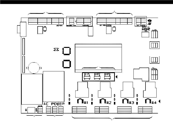
CPC-3 BOARD CALLOUTS
H G
|
INDUCER PORT |
|
|
FUTURE USE |
|
|
COMBUSTION AIR PORT |
|
FUTURE USE |
|
||||
|
|
|
|
|
|
|
|
|
|
|||||
S3SCS2S1M2M1MCMB |
D+D- |
RB |
P2P1G |
S1S2 |
GBRG |
R |
B |
S3SCS2S1M2M1MCMB |
RBD+D- |
P2P1G |
S1S2S1S2 |
|
||
|
|
INDUCER |
|
|
|
|
|
|
|
COMBUSTION AIR |
|
F |
||
|
|
MOTOR |
|
|
|
|
|
|
|
MOTOR |
|
|
||
|
|
ROTATION |
|
|
|
|
|
|
|
ROTATION |
|
NC |
||
|
|
SELECTOR |
|
|
|
|
|
|
|
SELECTOR |
|
REMOTE |
||
|
H1 |
|
|
|
|
|
|
|
G1 |
|
C |
ALARM |
||
|
|
|
|
|
|
|
|
|
NO |
PORT |
||||
|
|
|
I |
|
|
|
|
|
|
|
|
|
2 |
FUTURE |
|
|
|
RESET |
|
|
|
|
|
|
|
|
|
||
|
|
|
SWITCH |
|
|
|
|
|
|
|
|
1 |
USE |
|
KEYPAD |
|
|
|
|
|
CONTROLLER DISPLAY |
|
|
|
|
||||
CONNECTORS |
|
|
MICROCONTROLLERS |
|
|
|
|
|
|
|
|
FUTURE |
||
|
|
|
|
|
|
|
|
|
|
2 |
||||
|
|
|
|
|
|
|
|
|
C1 |
|
|
|
||
|
|
|
|
|
|
|
|
|
|
|
|
1 |
USE |
|
|
|
|
|
|
|
|
|
|
|
|
|
|
||
BOARD |
|
|
|
|
|
|
|
|
|
|
|
|
S1 |
E |
ALARM |
|
|
|
|
|
|
|
|
|
|
|
|
||
|
|
|
|
|
|
|
|
|
|
|
|
|
|
|
|
|
|
|
|
|
|
|
|
|
|
|
|
S2 |
AUXILIARY |
|
|
|
|
|
|
|
|
|
|
|
EXP-4E |
|
DEVICE |
|
|
|
|
|
|
|
|
|
|
|
|
|
O |
||
|
|
|
|
|
|
|
|
|
|
|
SIGNAL |
|
PORT |
|
|
|
|
|
|
|
|
|
|
|
|
|
C |
||
|
|
|
|
|
|
|
|
|
|
|
PORTS |
|
|
|
|
|
|
|
|
|
|
|
|
|
|
|
|
|
|
ANALOG AND |
|
|
|
|
|
|
|
|
|
|
|
|
|
|
DIGITAL |
|
|
|
|
|
|
|
|
|
|
|
|
|
|
POWER |
|
|
|
|
D1 |
|
|
|
D1 |
D1 |
|
D1 |
|
|
SUPPLIES |
|
|
|
|
|
|
|
|
|
|||||
|
|
|
|
|
|
|
|
|
|
|
|
|
|
|
|
|
|
|
|
DRY1 |
|
|
|
DRY2 |
|
DRY3 |
|
DRY4 |
|
A |
B |
|
|
|
A24V |
|
|
|
B24V |
|
C24V |
|
D24V |
CALL |
|
|
|
A115V |
|
|
|
B115V |
|
C115V |
|
D115V |
RETURN |
||
|
|
|
|
|
|
|
|
JUMPERS |
||||||
|
L N |
L N |
L N |
L N |
A B 1 2 3 4 |
|
|
A B 1 2 3 4 |
|
A B 1 2 3 4 |
A B 1 2 3 4 |
|
||
|
|
|
|
|
|
HEATER 1 |
|
|
HEATER 2 |
|
HEATER 3 |
HEATER 4 |
|
|
MAIN AC |
EXP-4E |
|
|
|
|
||
POWER TERMINAL |
POWER TERMINALS |
|
D |
|
C |
|
FIGURE 8081005
A)CPC-3 Main Power Switch
B)Power Supply Input Terminals: Accepts either 115 or 230 VAC, 50/60 Hz. 230V power can be suppied from VFD L & L Terminals.
C)Power Supply Output Terminals: Supply power to accessory EXP-4E Expansion boards.
C1) EXP-4E Expansion Modules: Communications connections from EXP-4E Expansion boards.
D)Heater Interlock Terminal Blocks (Four):
Positions A & B are for dry contact actuation, with A outputting 5 VDC and B needing 5 VDC to activate the CPC-3. Positions 1 & 2 require either 24 or 115 VAC from a heater control circuit to activate the CPC-3. A factory installed call return jumper wire above each terminal block routes the voltage connected from position 1 to position 3. When the CPC-3 safety circuit is made it switches position 3 to position 4, where the intercepted heater control circuit is routed back to the heater. Positions 3 & 4 are used independent of positions 1 & 2. If the A & B dry contacts are used to activate the CPC-3 (Call return jumper wire must be removed).
D1) IMPORTANT: Each six position terminal block includes a RED jumper tab to select the heater interlock voltage that is connected heater terminal block. Place RED jumper tab in Dry for positions A & B, 24V or 115V for positions 1 & 2 depening upon heater interlock voltage)
E)Auxiliary Device Terminals:
Used to activate a motorized damper/louver in series with the inducer/blower activation by switching power to device through terminal C & O. Position S1 outputs 5 VDC to be switched through a damper end switch and returned to position S2. This incorporates the end switch closure into the overall CPC-3 safety circuit. Positions S1 & S2 may also be used to react to the contact closure of a carbon monoxide alarm. The functions of C & O and S1 & S2 are independently activated through the Auxiliary Device key.
F) Remote Alarm Terminals:
Used to activate a remote alarm through either normally open or normally closed contacts. A power source is routed to the C position and returned out of either the N/C or N/O positions if an alarm condition exists.
G & H) Draft and Combustion Air Terminals:
The CPC-3 can independently control mechanical draft and combustion air inducers/blowers. While the software that runs these functions differs, the communications to the VFD's that control the inducer/blower is identical. The following information is applicable to both the Inducer and Combustion Air terminal strips.
5
 Loading...