


TJERNLUND PRODUCTS, INC. |
1601 Ninth Street • White Bear Lake, MN 55110-6794 |
PHONE (800) 255-4208 • (651) 426-2993 • FAX (651) 426-9547 |
Visit our web site • www.tjernlund.com |
CPC-2 SOFTWARE VERSION 3.02.02 ADDENDUM
1. New Data Display - | |
V 0.00 |
0.00I | |
Data on this line. |
| |
|
| |
Messages on this line. |
" " = key pad open; "F" = fault; "
 " = Inducer is in manual mode
2.New Fault Bandwidth - While the CPC-2 continues to maintain the setpoint pressure within +/-0.01" w.c., a fault will now occur after the actual pressure is +0.05" w.c. or
-0.02"w.c. away from setpoint for a duration of 90 seconds.
3.New Appliance Staging - Automatically stages appliances for a minimum of 10 seconds when multiple appliances "call" simultaneously. Pressure must reach and remain within bandwidth of pressure setpoint for 4 seconds before next appliance is allowed to fire.
4.Control Algorithm Change - The speed of acceleration towards the setpoint (gain) has been increased to improve the CPC-2 response time. The control architecture will now allow over shoot into the above setpoint region, resulting in fewer faults.
5.Control Algorithm Change - At start up, the computer program now has continuous
Inducer acceleration towards the setpoint. Originally, the program increased the Inducers
RPMs in four steps. That approach prevented over shooting the setpoint but it took longer to get there.
6.Restart Function - After a fault the CPC-2 will shut down the appliance(s). After a period of 60 seconds it will attempt a restart. If fault occurs again, then the CPC-2 will lock the appliances out until serviced. (Mechanical faults are excluded from restart).
7.Transducer Pressure Range Change - The model TD-2 transducer will now sense between +0.15" w.c. and -0.60" w.c. This increases the gain when operating at low system setpoints.
8.Fault Codes Expanded - New fault codes and messages let the service person know what is wrong and when it happened. The last four faults are automatically stored chronologically.
The fault duration has been expanded to 90 seconds from 60 seconds.
SEE CPC-2 FAULT CODES ON REVERSE SIDE
|
|
CPC-2 FAULT CODES |
|
FAULT |
OPERATING |
OPERATING |
|
CODE |
MODE |
STATE |
FAULT |
|
|
|
|
001 |
AUTOMATIC |
IDLE |
MECHANICAL |
011 |
AUTOMATIC |
PROVER START -UP |
MECHANICAL |
015 |
AUTOMATIC |
PROVER STARTUP |
PROVER |
021 |
AUTOMATIC |
SYSTEM START-UP |
MECHANICAL |
022 |
AUTOMATIC |
SYSTEM START-UP |
OVER DRAFT |
023 |
AUTOMATIC |
SYSTEM START-UP |
UNDER DRAFT |
025 |
AUTOMATIC |
SYSTEM START-UP |
PROVER |
031 |
AUTOMATIC |
PRE-PURGE |
MECHANICAL |
032 |
AUTOMATIC |
PRE-PURGE |
OVER DRAFT |
033 |
AUTOMATIC |
PRE-PURGE |
UNDER DRAFT |
035 |
AUTOMATIC |
PRE-PURGE |
PROVER |
041 |
AUTOMATIC |
SYSTEM RUN |
MECHANICAL |
042 |
AUTOMATIC |
SYSTEM RUN |
OVER DRAFT |
043 |
AUTOMATIC |
SYSTEM RUN |
UNDER DRAFT |
045 |
AUTOMATIC |
SYSTEM RUN |
PROVER |
051 |
AUTOMATIC |
POST PURGE |
MECHANICAL |
052 |
AUTOMATIC |
POST PURGE |
OVER DRAFT |
053 |
AUTOMATIC |
POST PURGE |
UNDER DRAFT |
055 |
AUTOMATIC |
POST PURGE |
PROVER |
101 |
MANUAL |
IDLE |
MECHANICAL |
111 |
MANUAL |
PROVER START-UP |
MECHANICAL |
115 |
MANUAL |
PROVER START-UP |
PROVER |
131 |
MANUAL |
PRE-PURGE |
MECHANICAL |
135 |
MANUAL |
PRE-PURGE |
PROVER |
141 |
MANUAL |
SYSTEM RUN |
MECHANICAL |
145 |
MANUAL |
SYSTEM RUN |
PROVER |
151 |
MANUAL |
POST PURGE |
MECHANICAL |
155 |
MANUAL |
POST PURGE |
PROVER |
241 |
VENTER ONLY |
SYSTEM RUN |
MECHANICAL |
P/N: 8505015 |
©2002 TJERNLUND PRODUCTS, INC. ALL RIGHTS RESERVED |
REV. 1/02 |
REV. A 3/01


 TJERNLUND PRODUCTS, INC.
1601 Ninth Street • White Bear Lake, MN 55110-6794
PHONE (800) 255-4208 • (651) 426-2993 • FAX (651) 426-9547 Visit our web site • www.tjernlund.com
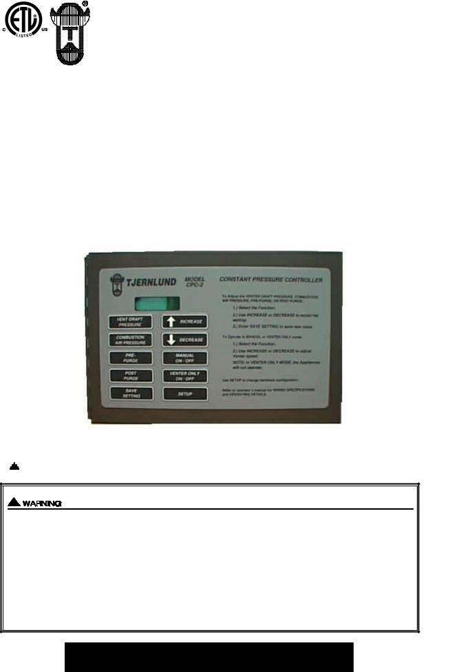
MODEL
CPC-2
CONSTANT PRESSURE CONTROLLER
For Controlling Variable Speed Auto-Draft® Venters, Combustion Air IN-FORCERTMS, Power Venters and Draft Inducers with multiple appliances
OWNER INSTRUCTIONS, DO NOT DESTROY
 Recognize this symbol as an indication of important Safety Information!
THESE INSTRUCTIONS ARE INTENDED AS AN AID TO QUALIFIED, LICENSED SERVICE PERSONNEL FOR PROPER INSTALLATION, ADJUSTMENT AND OPERATION OF THIS UNIT. READ THESE INSTRUCTIONS THOROUGHLY BEFORE ATTEMPTING INSTALLATION OR OPERATION. FAILURE TO FOLLOW THESE INSTRUCTIONS MAY RESULT IN IMPROPER INSTALLATION, ADJUSTMENT, SERVICE OR MAINTENANCE POSSIBLY RESULTING IN FIRE, ELECTRICAL SHOCK, CARBON MONOXIDE POISONING, EXPLOSION, OR PERSONAL INJURY OR PROPERTY DAMAGE.
PLEASE READ CAREFULLY AND KEEP ON JOB
SITE FOR FUTURE REFERENCE.
Copyright © 2000, Tjernlund Products, Inc. All rights reserved. |
P/N 8504091 |

TABLE OF CONTENTS |
|
|
Page(s) |
Description and Operation............................................................................................................................................... |
1 |
Specifications .................................................................................................................................................................. |
1 |
Cautions .......................................................................................................................................................................... |
2 |
Installation of CPC-2, Transducer & Balancing Dampers ............................................................................................... |
2 |
CPC-2 Circuit Board Features & Circuit Board Layout ................................................................................................ |
2-4 |
Modes of Operation and Programming CPC-2 Controller ........................................................................................... |
5-7 |
Initial System Power Up and Setup of CPC-2 ............................................................................................................. |
7-9 |
CPC-2 Fault Messages .............................................................................................................................................. |
9-10 |
Wiring........................................................................................................................................................................ |
10-13 |
Replacement Parts & Warranty ..................................................................................................................................... |
14 |
Tjernlund Products welcomes your comments and questions. Call us at 800-255-4208, Fax 651-426-9547, Email us at fanmail@tjfans.com or write to: Customer Service, Tjernlund Products, Inc., 1601 Ninth Street, White Bear Lake, MN 55110-6794.
DESCRIPTION AND OPERATION
The CPC-2 controls the motor speed of Tjernlund variable speed Auto-Draft® Venters, Draft Inducers, Power Venters and Combustion Air In-Forcers. It requires a Pressure Transducer and a Tjernlund Variable Frequency Drive (VFD) to automatically modulate motor speed. The installer/user may select a pressure set point via the key pad on the CPC-2. The transducer outputs a signal to the CPC-2 proportional to the pressure or draft that it senses. The CPC-2 outputs a proportional signal to the VFD, which modulates the frequency of the voltage to the motor, causing it to speed up or slow down so that the pressure or draft set point is maintained.
Integral to the CPC-2 are two heating appliance interlock circuits. When an appliance calls for heat the burner control signal is intercepted, causing the Auto-Draft® Venter, Draft Inducer, Power Venter or Combustion Air In-Forcer to speed up until the pressure set point is reached. If the set point is not reached within CPC-2 allowable limits (See Modes of Operation), the interlocked appliance(s) will not fire.
When a pre-purge time is selected the controller will not allow the appliance(s) to operate until the pressure set point is reached and the pre-purge time has elapsed. When a post-purge time is selected the appliances are deactivated as soon as the call for heat is satisfied, but the Auto-Draft® Venter, Draft Inducer, Power Venter or Combustion Air In-Forcer will continue to maintain the pressure set point until the post-purge time has elapsed. The secondary Fan Prover Switch model PSA-1 is adjusted by the installer to the vent system draft set point and wires into a terminal strip on the CPC-2. The Transducer in conjunction with the CPC-2 Controller is considered the primary draft proving control.
The CPC-2 can also be operated in the Manual mode, regulating the motor at a constant, user set speed. The Venter Only mode allows the user to regulate the motor at a constant, user set speed, but will not allow any interlocked heating appliances to operate.
COMPLETE AUTO-DRAFT® VENT SYSTEM SOLUTIONS
This installation manual does not contain any system design documentation. Installation and use of Auto-Draft® Venters or EXP-4 Appliance Interlock Expansion boards are not covered by this manual. Please refer to those accessory installation manuals.
SPECIFICATIONS |
1 |
CAUTIONS
1.Failure to install, maintain and/or operate the CPC-2 in accordance with manufacturer’s instructions may result in conditions that can produce bodily injury and property damage.
2.The safety interlock and system operation performance checks must be performed on each appliance interlocked with the CPC-2 in accordance with the Auto-Draft® Venter, IN-FORCER Combustion Air Intake, Power Venter or Draft Inducer installation instructions.
INSTALLATION AND LOCATION OF CPC-2, TRANSDUCER AND BALANCING DAMPERS
MOUNTING OF THE CPC-2
CPC-2 and transducer should be mounted conveniently inside mechanical room where access is not restricted. Since set up requires adjustment of draft settings, close proximity to heating equipment is suggested.
MOUNTING OF THE TRANSDUCER
The transducer must be mounted indoors within six (6) feet of the vent or chimney transducer sampling tube.
MOUNTING OF TRANSDUCER SAMPLING TUBE
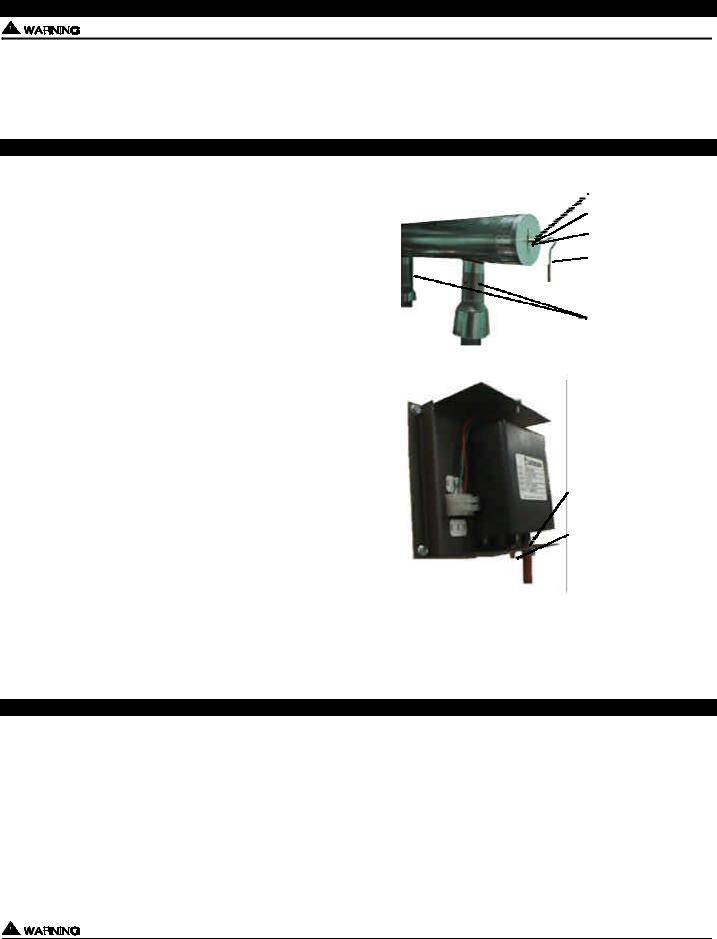
The CPC-2 operates best when the transducer sampling tube measures static pressure, not velocity pressure. The best position to measure static pressure is in an extension off of the back end of a horizontal manifold, (See Diagram A). At this position the probe is not influenced by the velocity of the flue gases being exhausted. Do not use an elbow to connect the last appliance (furthest from venter) to the common manifold. The elbow will not allow the sampling tube to measure static pressure. If necessary, “T” off manifold as close to last appliance as possible preferably using the same diameter pipe as manifold and a clean, burr free transition. Drill 1/4” sampling hole in vent or chimney for sampling tube. Insert stainless steel sampling tube through 1/4” hole just enough to penetrate interior of vent pipe and lock in place with compression nut, (See Diagram A). With the Venter on, a reading with a draft gauge can be used to determine when interior of pipe has been penetrated.
CONNECTING TRANSDUCER TO SAMPLING TUBE
The transducer - negative pressure front port (closest to cover) is connected to the transducer sampling tube. Make sure the silicone tubing has no sharp bends or kinks in it. The high pressure rear port (closest to mounting bracket) must be left open to room atmosphere, (See Diagram B).
DIAGRAM A
 COMPRESSION NUT
COMPRESSION FERRULE
SAMPLING PORT CENTERED
OVER 1/4” HOLE
1/4” STAINLESS STEEL SAMPLING TUBE BEND MUST FACE UPWARDS.
INDIVIDUAL APPLIANCE
BALANCING DAMPERS ARE
NECESSARY. MAKE SURE
THEY DO NOT INTERFERE
WITH FLUE DAMPERS.
DIAGRAM B
FRONT NEGATIVE PRESSURE
PORT CLOSEST TO JUNCTION
BOX COVER MUST BE CONNECT-
ED TO SAMPLING PORT WITH
SILICONE TUBING.
REAR HIGH PRESSURE PORT
CLOSEST TO MOUNTING BRACK-
ET MUST BE LEFT OPEN TO
ROOM ATMOSPHERE.
BALANCING DAMPER INSTALLATION
Balancing dampers are necessary on each appliance vent riser into the common vent manifold. Since the Venter will pull flue gases from the point of least resistance, those appliances connected closest to the venter will tend to overdraft. Balancing dampers can be adjusted to match each individual appliance draft requirement, (See Diagram A). Care should be taken so balancing dampers do not interfere with flue dampers if on equipment. Tjernlund’s ABD-Series (4-10”, 12” & 14” diameter) balancing dampers are constructed out of 304 stainless steel and feature a tamper proof locking adjustment.
CPC-2 CIRCUIT BOARD FEATURES
Two closed loop channels allowing independent variable speed control of both venting and combustion air systems.
Two appliance interlocks for control circuit voltages between 18 & 240 VAC plus two sets of dry contacts for activation by gas pressure switch or boiler sequencer dry contacts. Additional appliances can be interlocked by using the optional EXP-4 expansion board. Up to three EXP-4 expansion boards can be connected to interlock up to 14 appliances into a single CPC-2.
Switchable 120/230 VAC 50/60 Hz. fused power supply.
Dry Contact alarm circuit that reacts to motor high limits, tilt switches, prover faults, under pressure conditions.
LED lights displayed for Venter Check circuit, appliance call for heat, prover circuit completed and CPC-2 power supplied to board. See CPC-2 Circuit Board Call Outs for LED indicator light status.
Serial Port interface.
All sensor connections to the CPC-2 control must only be connected to Tjernlund approved components. Failure to install, maintain and/or operate the CPC-2 in accordance with manufacturer’s instructions may result in conditions that can produce bodily injury and property damage.
2
CPC-2 CIRCUIT BOARD CALL OUTS
1) ALARM: Dry contacts will close with a Venter Fault or any fault that requires manual resetting. These faults include the Venter, Start-up, Prover 1 or Prover 2 Faults. Connect to aux. alarm or building mgmt. system. Rated for 1/4 h.p. @ 120 VAC.
2)SERIAL PORT: For inputting future program updates and outputting stored data.
3)PROVER 2: Connection to auxiliary prover for second CPC-2 controlled device. (i.e. Combustion Air In-Forcer or future needs)
4)VENTER 2: Connection to VFD of second CPC-2 controlled device. (i.e. Combustion Air In-Forcer) (0-10 VDC output)
5)SENSOR 1: Connection to vent pressure Transducer to regulate Venter / Inducer speed. (0-10 VDC input)
6)SENSOR 2: Connection to secondary vent pressure Transducer that communicates with CPC-2 to regulate motor speed of
secondary device. (i.e. Combustion Air In-Forcer) (1-12 VDC input)
7)SENSOR 3: Connection to future sensor (open connection, not currently programmed) (0-10 VDC input)
8)SENSOR 4: Connection to future sensor (open connection, not currently programmed) (0-10 VDC input)
9)VENTER 1: Connection to VFD of Venter / Inducer. (1-10 VDC output)
10)PROVER 1: Connection to secondary Fan Prover, i.e. PSA-1 adjustable Fan Prover.
11)MOTOR SENSOR: Green LED indicates that Venter check circuit, i.e. motor limits, housing access limits, high limits, etc.,
are closed and in an acceptable condition.
12)DISPLAY: CPC-2 connection to ribbon cable from display. Ribbon cable printing must face towards top of CPC-2 electrical box.
13)MOTOR SENSOR TERMINAL STRIP: Connects to terminal strip of VFD to lock out interlocked appliances if any motor limit
trips. Relay closes alarm dry contacts (position 1).
14)18-130 VAC JUMPER TAB: Jumper tab must be removed for 230 VAC interlock with appliance #1.
15)CALL 1: Yellow LED indicates that 1st interlocked appliance is calling for heat.
16)APPLIANCE ON 1: Green LED indicates that vent pressure set point has been reached/maintained and the interlocked
appliance call for heat signal has been delivered to the burner control circuit.
17)RESET BUTTON: Used to soft boot CPC-2 control.
18)CALL 2: Yellow LED indicates that 2nd interlocked appliance is calling for heat.
19)APPLIANCE ON 2: Green LED indicates that vent pressure set point has been reached/maintained and the interlocked
appliance call for heat signal has been delivered to the burner control circuit.
20) DRY CONTACT JUMPER TAB: Jumper tab must be installed if using dry contacts for interlock with appliance #1. Important: Do not use appliance #1 interlock terminal strip (position 30) if using dry contact actuation.
21) APPLIANCE #1 INTERLOCK JUMPER:
22) DRY CONTACT JUMPER TAB: Jumper tab must be installed if using dry contacts for interlock with appliance #2. Important: Do not use appliance #2 interlock terminal strip (position 32) if using dry contact actuation.
23)18-130 VAC JUMPER TAB: Jumper tab must be removed for 230 VAC interlock with appliance #2.
24)APPLIANCE #2 INTERLOCK JUMPER: Routes intercepted control circuit “hot” voltage from position #1 to position #3, completing
circuit back to appliance through position #4 when all safeties are closed. Normally kept in place. If removed user can actuate the CPC-2 with one voltage and actuate the appliance control circuit with another.
25)KEYPAD: CPC-2 connection to ribbon cable from keypad.
26)SYSTEM POWER LIGHT: Red LED indicates that the CPC-2 has power.
27)VOLTAGE SELECTION SWITCH: Allows the installer to select between 115 VAC and 230 VAC for the main power input to the CPC-2.
28)ON/OFF SWITCH: Turns power to CPC-2 on or off.
29)APPLIANCE #1 DRY CONTACT INTERLOCK TERMINAL: For dry contact actuation of CPC-2. Must install jumper at position 20.
30)APPLIANCE #1 INTERLOCK TERMINAL : Term. 1 & 2: 24 to 230 VAC input, Term. 3 & 4: Contacts rated 1 hp @ 120 VAC.
31)APPLIANCE #2 DRY CONTACT INTERLOCK TERMINAL: For dry contact actuation of CPC-2. Must install jumper at position 21.
32)APPLIANCE #2 INTERLOCK TERMINAL: Term. 1 & 2: 24 to 230 VAC input, Term. 3 & 4: Contacts rated 1 hp @ 120 VAC.
33)EXPANSION BOARD 1: Terminal strip power and ribbon cable interlock connection to optional EXP-4 appliance interlock
expansion board. (Controls appliances 3 - 6)
34) EXPANSION BOARD 2: Terminal strip power and ribbon cable interlock connection to optional EXP-4 appliance interlock expansion board. (Controls appliances 7 - 10)
35) EXPANSION BOARD 3: Terminal strip power and ribbon cable interlock connection to optional EXP-4 appliance interlock expansion board. (Controls appliances 11 - 14)
36) MAIN POWER: Primary power connection for CPC-2. May be wired to either 115 VAC single phase or 230 VAC single phase. Also provides power to any EXP-4 expansion boards connected to CPC-2.
37) CPC-2 MAIN POWER INPUT FUSE: Replaceable 1.5 amp fuse.
3
 Loading...