


REV. 3 9/97
TJERNLUND PRODUCTS, INC. |
1601 Ninth Street • White Bear Lake, MN 55110-6794 |
PHONE (800) 255-4208 • (651) 426-2993 • FAX (651) 426-9547 |
Visit our web site • www.tjernlund.com |
MODELS DESCRIPTION
GPAK-J FOR GAS APPLIANCES WITH A BTU/HR INPUT OF 120,000 OR LESS
GPAK-JT FOR GAS APPLIANCES WITH A BTU/HR INPUT OF 120,000 OR LESS WHICH REQUIRE A POWER VENTER POST PURGE
GPAK-1 FOR GAS APPLIANCES WITH A BTU/HR INPUT FROM 100,000 TO 250,000
GPAK-1T FOR GAS APPLIANCES WITH A BTU/HR INPUT FROM 100,000 TO 250,000 WHICH REQUIRE A POWER VENTER POST PURGE
OWNER INSTRUCTIONS, DO NOT DESTROY
 Recognize this symbol as an indication of important Safety Information!
NOTE: FLUE GAS TEMPERATURES MUST NOT EXCEED 600oF AT VENT SYSTEM INLET.
THESE INSTRUCTIONS ARE INTENDED AS AN AID TO QUALIFIED, LICENSED SERVICE PERSONNEL FOR PROPER INSTALLATION, ADJUSTMENT AND OPERATION OF THIS UNIT. READ THESE INSTRUCTIONS THOROUGHLY BEFORE ATTEMPTING INSTALLATION OR OPERATION. FAILURE TO FOLLOW THESE INSTRUCTIONS MAY RESULT IN IMPROPER INSTALLATION, ADJUSTMENT, SERVICE OR MAINTENANCE POSSIBLY RESULTING IN FIRE, ELECTRICAL SHOCK, CARBON MONOXIDE POISONING, EXPLOSION, OR PERSONAL INJURY OR PROPERTY DAMAGE.
DO NOT DESTROY. PLEASE READ CAREFULLY AND KEEP
IN A SAFE PLACE ON JOB SITE FOR FUTURE REFERENCE.
Copyright © 1995, Tjernlund Products, Inc. All rights reserved. |
P/N 8504013 |

TABLE OF CONTENTS |
|
|
PAGE(S) |
GPAK DESCRIPTION .................................................................................................................................................. |
1 |
GPAK SIZING ................................................................................................................................................................ |
1 |
SPECIFICATIONS ......................................................................................................................................................... |
2 |
INSTALLATION RESTRICTIONS .............................................................................................................................. |
2-3 |
INSTALLER NOTES...................................................................................................................................................... |
3 |
SAFETY INSPECTION OF EXISTING APPLIANCE INSTALLATION .......................................................................... |
4 |
VENT HOOD LOCATION & INSTALLATION ............................................................................................................. |
4-5 |
POWER VENTER INSTALLATION ............................................................................................................................ |
5-7 |
ELECTRICAL WIRING .............................................................................................................................................. |
7-12 |
INSTALLATION RESTRICTIONS ................................................................................................................... |
7 |
SEQUENCE OF OPERATION ........................................................................................................................ |
7 |
WIRING TO GAS VALVE ............................................................................................................................. |
8-9 |
ALTERNATIVE WIRING WITH THERMOSTAT ....................................................................................... |
10-11 |
OPERATION CIRCUIT CHECK .................................................................................................................................. |
12 |
SAFETY INTERLOCK/COMBUSTION AIR TEST ....................................................................................................... |
12 |
AIR FLOW ADJUSTMENT .......................................................................................................................................... |
13 |
MAINTENANCE .......................................................................................................................................................... |
13 |
TROUBLESHOOTING ........................................................................................................................................... |
13-15 |
HOW TO OBTAIN SERVICE & LIMITED WARRANTY ......................................................................................... |
15-16 |
PERFORMANCE CURVES ................................................................................................................................... |
16-17 |
VH1-4 VENT HOOD MOUNTING TEMPLATE ........................................................................................................... |
18 |
Tjernlund Products welcomes your comments and questions. Call us at 1-800-255-4208, Fax 612-426-9547 or write to: Customer Service, Tjernlund Products, Inc., 1601 Ninth Street, White Bear Lake, MN 55110-6794.
GPAK DESCRIPTION
The GPAK is a complete venting system designed to Side Wall Vent Natural and LP gas heating appliances. Each GPAK comes with two major components: the Power Venter and the Vent Hood. The GPAK-J and GPAK-JT are identical in performance, each can handle a maximum BTU/HR input of 120,000. The GPAK-1 and GPAK-1T are identical in performance, each can handle BTU/HR inputs from 100,000 to 250,000. The “T” of the GPAK-JT and GPAK-1T indicates these kits have a post purge Relay/Timer which allows the Power Venter to continue operating for a non-adjustable period of approximately 45 seconds after the appliance burner shuts off. The GPAK-J and GPAK-1 are equipped with a 24/115V Relay without the post purge feature.
GPAK SIZING
Verify that the GPAK you are about to install is properly sized for the appliance.
1.If installing the GPAK-J or GPAK-JT, confirm that the BTU/HR. input of the appliance is 120,000 or less. If installing the GPAK-1 or GPAK-1T, confirm that the BTU/HR. input of the appliance is between 100,000 and 250,000.
2.Determine that the equivalent vent pipe length to be installed is within the appropriate GPAK’s performance. An example of calculating the equivalent vent pipe length is shown on page 2.
NOTES |
MODEL SELECTION TABLE |
1. If the appliance flue outlet is greater than 4”, install a |
|
tapered reducer directly after the draft hood, draft |
|
diverter or barometric draft control, reducing vent pipe |
|
diameter to 4”. All vent pipe from the appliance to the |
|
Power Venter may be 4”. |
|
2. Table is based on straight vent pipe. 90 degree |
|
elbows are equivalent to 6 feet of straight vent pipe, |
|
45 degree elbows are equivalent to 3 feet of straight |
|
vent pipe. An example of calculating equivalent pipe |
|
length is on top of page 2. |
|
3. Determine maximum pipe length from type of equip- |
|
ment being vented and GPAK Model. Category A |
|
pipe runs over 30 linear feet should use Type “B” |
|
vent. Category B & C pipe runs over 15 linear feet |
|
should use Type “B” vent. |
|
4.Column C allows for up to a 40,000 BTU/hr. Input atmospheric water heater common vented with a fan assisted appliance from column B.
5.All reducers and vent pipe are to be supplied by the installer and are available from your local heating wholesaler.
1

EQUIVALENT PIPE LENGTH CALCULATION EXAMPLE
SPECIFICATIONS
ELECTRICAL SPECIFICATIONS
POWER VENTER
VENT HOOD
INSTALLATION RESTRICTIONS
Do not install the Power Venter on incinerators, condensing type appliances or solid-fuel burning appliances. Only install the Power Venter on appliances equipped with a draft hood, draft diverter or barometric draft control.
Do not install the Power Venter on an appliance with an automatic valve having a manual opener unless the manual opener has been rendered inoperative or the automatic valve has been replaced with a valve not equipped with a manual opener.
Failure to install, maintain and/or operate the Power Venter in accordance with manufacturer's instructions may result in conditions which can produce bodily injury and property damage.
2
The Power Venter must be installed by a qualified installer in accordance with these instructions and all local codes or in their absence in accordance with the latest edition of The National Fuel Gas Code (NFPA #54), the latest edition of the National Electrical Code (NFPA#70) and the Occupational Safety and Health Act (OSHA) when applicable. Improper installation can create a hazardous condition such as an explosion, fire, electrical shock or carbon monoxide poisoning resulting in property damage, personal injury or death.
Disconnect the power supply when making wiring connections or when working around the fan wheel and motor. Failure to do so can result in electrical shock, personal injury, death or property damage.
1.“Qualified Installer” shall mean an individual properly trained and licensed
2.The installer must write or imprint name, phone number, date of installation and sign in the appropriate space on the Power Venter nameplate.
3.Plan the vent system so that Code required distances are maintained from plumbing and wiring.
4.The Power Venter motor shaft must be mounted horizontally to ensure proper operation of the Fan Proving Switch and prevent motor bearing wear.
5.Make certain the power supply is adequate for the fan motor requirements. Do not add the Power Venter to a circuit where the total load is unknown.
6.The installer must verify that the BTU/hr. input of the appliance does not exceed the recommended input of the GPAK. See selection table on page 1 of these instructions for sizing information.
7.Flue gas temperatures must not exceed 600 degrees F. at the Power Venter inlet. Ambient temperatures must not exceed 104 degrees F. Temperatures above this range can cause a fire resulting in property damage, personal injury or death.
8.A safety inspection of an existing appliance must be performed before installation of the GPAK as outlined in ANSI Z223.1/NFPA #54, Appendix H, see top of page 4.
9.The electrical load controlled through the Fan Proving Switch must not exceed the electrical ratings marked on the Fan Prover.
Improper installation, adjustment, alterations, service or maintenance can cause injury or property damage. Refer to this manual. For assistance or additional information consult a qualified installer, service agency or the gas supplier.
INSTALLER NOTES
1.The installer must read and follow these instructions carefully to assure proper installation and operation of the GPAK.
2.The installer must fill in the required information on the nameplate located on the Power Venter electrical box cover.
3.The installer must affix the appropriate wiring diagram label included with these instructions to the appliance casing adjacent to its rating plate.
4.The appliance(s) may only be installed on the suction side of Power Venter.
5.The installer must notify the homeowner of the maintenance required with the use of the product.
6.The installer must verify that the pilot safety controls (if so equipped) of the appliance are in good operating condition before installation of the GPAK.
7.No more that 2 appliances may be vented by the GPAK.
8.The Power Venter must not be installed into any portion of a vent system which serves appliances other than the one(s) vented by the GPAK.
9.The installer must shut off all electricity and gas to the appliance using the appliance circuit breaker/fuse for the electricity and shut off valve in the supply line to the appliance for the gas before installation of the GPAK.
10.If installing the GPAK on a furnace, the installer must check the limit and fan control for proper operation. Limit control operation can be checked by blocking the circulating air inlet or temporarily disconnecting the electrical supply to the blower motor and determining that the limit control acts to shut off the main burner gas.
11.If installing the GPAK on a boiler, the installer must determine that the water pumps, low water cutoffs, automatic feed controls, pressure temperature limit controls and relief valves are in proper operating condition by following the manufacturer’s recommended testing procedure.
3
*SAFETY INSPECTION OF A PREVIOUSLY USED GAS APPLIANCE
(Perform prior to GPAK installation)
The following procedure is intended as a guide to aid in determining that an appliance is properly installed and is in safe condition for continuing use.
The following procedure is based on central furnace and boiler installations and it should be recognized that generalized procedures cannot anticipate all situations. Accordingly, in some cases deviation from this procedure may be necessary to determine safe operation of the equipment.
a.Perform this procedure prior to any attempt at modifications of the appliance or installation of the GPAK.
b.If it is determined there is a condition which could result in unsafe operation, shut off the appliance and advise the owner of the unsafe condition.
Follow the steps below in making the safety inspection:
1.Conduct a gas leakage test of the appliance piping and control system downstream of the shutoff valve in the supply line to the appliance.
2.Visually inspect the venting system and determine there is no blockage or restriction, leakage, corrosion and other deficiencies which could cause an unsafe condition.
3.Shut off all gas to the appliance(s).
4.Inspect burners and crossovers for blockage and corrosion.
5.Applicable only to furnaces: Inspect heat exchanger for cracks, openings or excessive corrosion. Check both the limit control and fan control for proper operation.
6.Applicable only to boilers: Inspect for evidence of water or combustion product leaks. Determine that the water pumps are in
operating condition. Test low water cutoffs, automatic feed controls, pressure and temperature limit controls and relief valves in accordance with the manufacturer's recommendations to determine that they are in operating order.
* Excerpts from the National Fuel Gas Code (ANSI Z223.1/NFPA #54), Appendix H.
VENT HOOD LOCATION
If possible, locate the Vent Hood on a wall that does not face the direction of prevailing winds. This will diminish the possibility of appliance interruption during periods of extreme winds.
If possible, locate the Vent Hood no closer than 3 feet from an inside corner of an L-shaped structure.
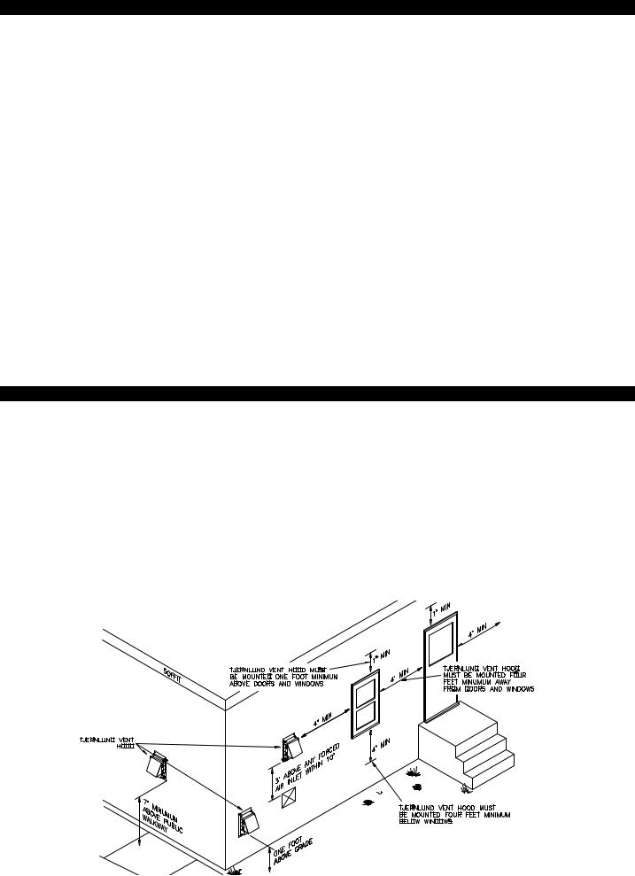
CODE REQUIREMENTS
Terminate the vent system so that proper minimum clearances are maintained as cited in the latest edition of the National Fuel Gas Code (NFPA # 54) and the latest edition of NFPA #211, or as follows:
•Not be less than 7 feet above grade when located adjacent to public walk ways.
•At least 3 feet above any forced air inlet located within 10 feet.
•At least 4 feet below, 4 feet horizontally from or 1 foot above any door, window or gravity air inlet into any building.
•At least 12 inches above grade.
•So that the flue gases are not directed so as to jeopardize people, overheat combustible structures or enter buildings, and
•Not less than 2 feet from an adjacent building.
4
VENT HOOD INSTALLATION
1.Attach the template on page 18 to the interior of the wall the vent hood will be penetrating.
2.Verify that wall penetration will not come in contact with concealed wiring or plumbing. Using a 1/2” drill bit, drill two pilot holes where noted on the template. The drill bit must be long enough to penetrate to the building exterior.
3.Attach the template to the building exterior aligning the pilot holes on the template with the pilot holes drilled in step 2.
4.Using a reciprocating saw, cut an opening through the building siding, wall board, etc., following the appropriate lines of the template.
5.Slide the Vent Hood through the opening and fasten to exterior wall using provided screws.
6.Once Power Venter is completely installed and secured, apply a bead of exterior rated caulk between Vent Hood flange and exterior of building.
POWER VENTER INSTALLATION
CODE REQUIREMENTS
The Power Venter installation must be done in accordance with the following requirements of the latest Edition of the National Fuel Gas Code (NFPA #54):
•All portions of the vent system under positive pressure during operation (on the outlet side of Power Venter) shall be designed and installed so as to prevent leakage of flue or vent gases into the building,
•All appliances must enter the vent system on the inlet side of the Power Venter,
•Provision shall be made to interlock the appliance(s) to prevent the flow of gas to the main burners when the draft system is not performing so as to satisfy the operating requirements of the equipment for safe performance. See “Electrical Wiring” section of this manual for details.
INSTALLER NOTES
1.All vent pipe and reducers must be supplied by the installer and are available from your heating wholesaler.
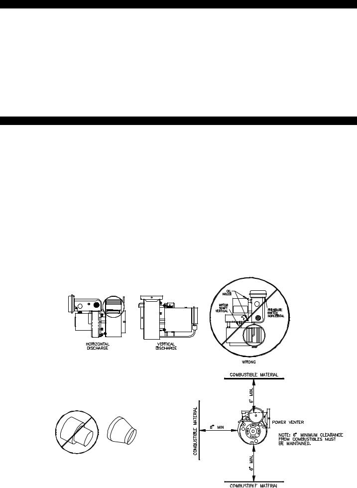
2.To prevent motor bearing wear and to ensure proper Fan Proving Switch operation, the Power Venter must be mounted with shaft of the motor horizontal, (See Diagram A).
DIAGRAM A
3. If the appliance flue is greater than 4 inch, install a tapered reducer on the appliance and run 4 inch vent pipe from the appliance to the Power Venter,(See Diagram B).
DIAGRAM C
DIAGRAM B
4. The Power Venter housing is single wall, a 6 inch clearance to combustible materials must be maintained,(See Diagram C).
5
 Loading...